Output Device
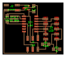
This week assignment is to add an output device to a microcotroller board and program it to do something. Because there are high probabilities for me to use the LCD I chose it. The first task was to get the design for the LCD circuit.
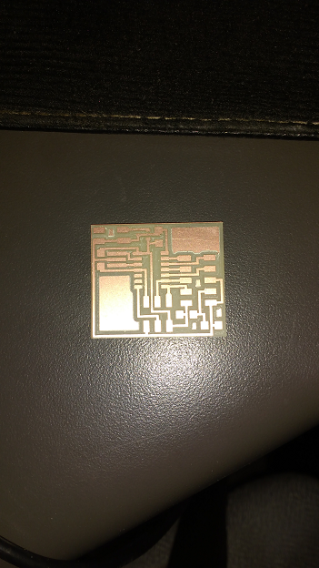
Then it was milled on the Roland Modela. The result is show below:
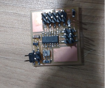
Afterwars is the solder of the components:
- Resistence 100k
- Resistance 10k
- Resistance 1k
- Capacitor 1uF
- Resonator 20MHz
- Pin headers
- Attiny44
Then I need to download the program into the controller. For that I used the procedure specify on week XX. For the connections of the LCD is importante to point out the following:
- Pin GND – Ground
- Pin VCC – voltage entrance for the system.
- Pin Vee – for constrast. It is usually used a potentiometer.
- Pin RS – if it is high the LCD receive data to display. In the other case the system will receive commands like for example clear() or setCursor().
- Pin R/W – When it is low the LCD show the data transmited. If it is high a microcontroller can read the data over the display.
- Pin Enable – it enable communication.
- Pin DB4-DB7 – pins used for data transfer. Pins from DB0 to DB3 are not necessary.
- Pins Led+ and Led- are for turning on the back light. I connected these pins for the firs time.
Serial communication is established between the Attiny44 and the LCD for making possible the pass of data from the controller to the actuator. For this time there was no need to change the programs from the lecture files. However, if somenone want to change the information inside the LCD, one just have to go to the C file and rewrite the next line:
static const char line1[] PROGMEM = "XXXX"
static const char line2[] PROGMEM = "XXXX"
And write their messaage instead of "XXXX". Be carefull to separate the upper letters (line1) form the lower letters (line2)
There was no mayor issue doing this assignemnt and there was no need to check the datasheet.
The next videos show the results from this experience.
The board design can be downloaded from this link. It is base on the board from the lecture.