Electronic Design
The assignment of this week was to redraw the "echo hello-word board" and add at least a button and a led into the system. For this project I used the software "Eagle", a software used for creating electronic schematics and board. For more information, visit its web page: http://www.cadsoftusa.com/

At first I studied the board image to get and idea of what to do.
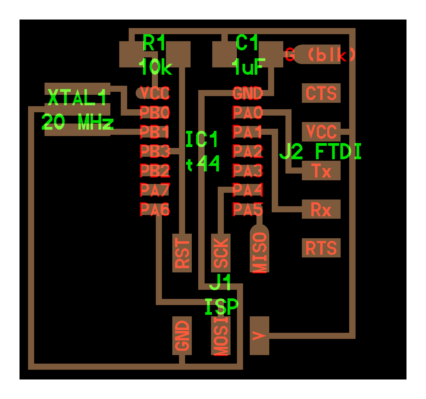
The components required for the board are quite simple and easy to get. They were:
- Capacitor 1uF (SMD)
- Resistance 10K ohms (SMD)
- ATtiny 44 (SMD)FTDI Headers
- 2x3 header
- Crystal of 20MHz (SMD)
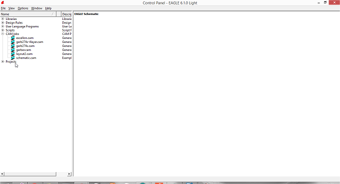
Now is time to start working in the project. First I opened Eagle and the next window appeared in the screen.
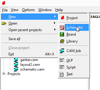
We need to start creating a schematic file. The schematic file is where we design the circuit and connect components independant of their physical appearence.
After making the shematic file the next window will display:
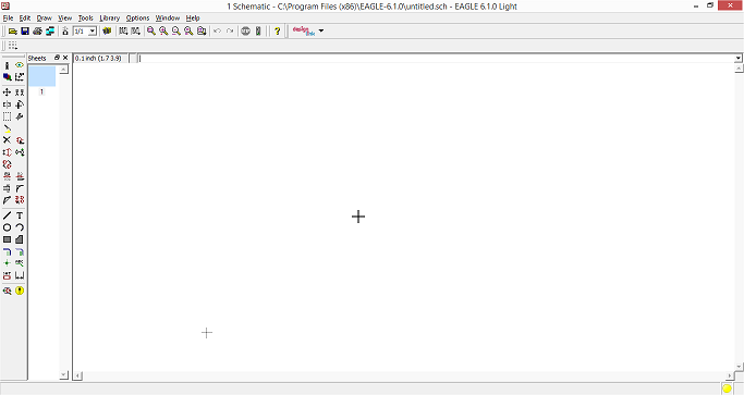
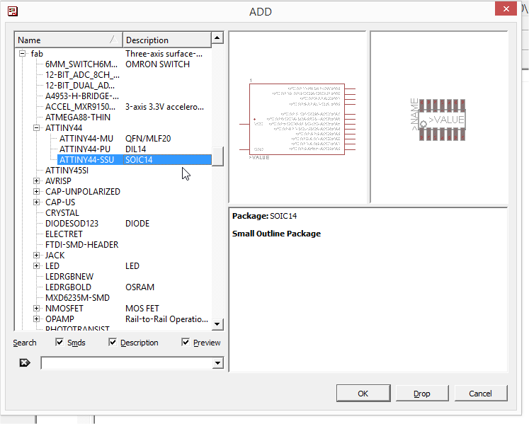
The workspace is the big white space and the menu toolbar is at the left side. The first step is to add the components inside the workspace. For that we need to click over the ADD icon.

Over the menu option that emerged we look for the components, writing them on the text box. Other option to get the components is to search over the different families components submenus. In our case, we have all the materials under "fab" family. After we find them, we double click over their name and drag them to the white space
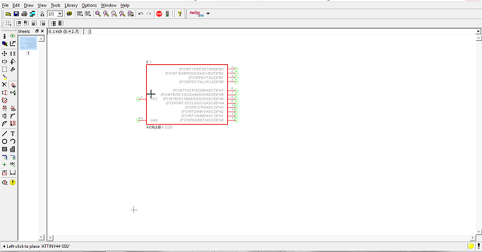
If by any change we want to move any item, we could use the move button.

We select it and click over the element we want and start draging it inside the workspace. A second click is to leave the element over its place.
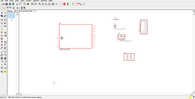
For connecting devices, we choose the line button from the tool menu.

And click over the first component pin. A dark green line should be display whe the mouse is move. A second click over the pin of other device will connect both of them. To see the connection just click over the eye button:

and second click over the line. The join elements will bright their colors.
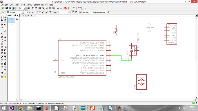
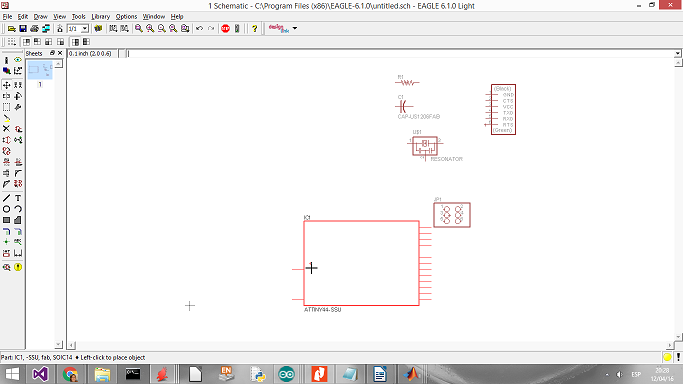
After making all the connections, it should look like the following picture:
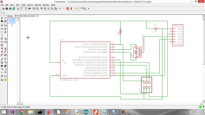
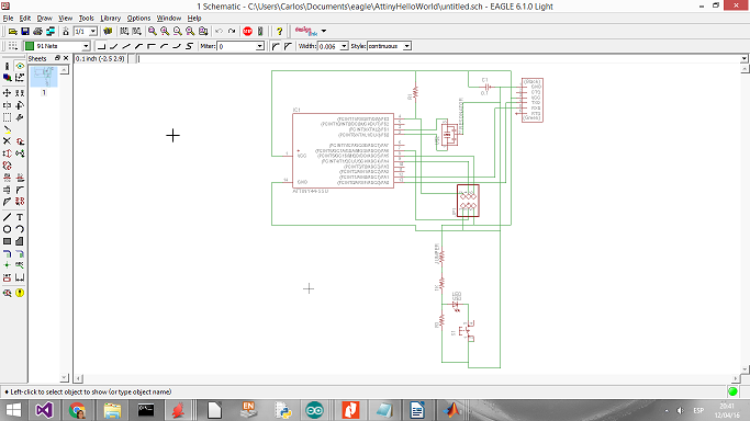
However, this is only a copy from the original file, so I add a button, a LED and to resisitors for making a pull down system for the bottom. For more information see the next web page at Wikipedia The final schematic should look like this:
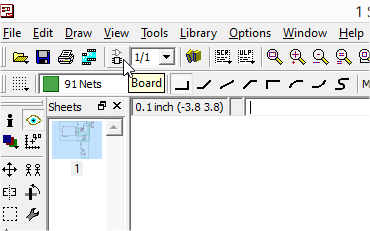
Now is time to make the board with the actual components. For that, click over the top button "board". The window for creating the board will emerged. Inside this page the components will exposed with their dimensions in order to see how the end product will be.
The next image is presented:
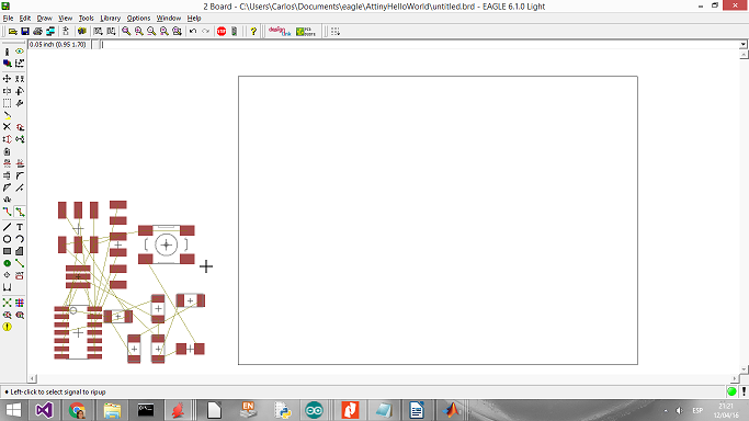
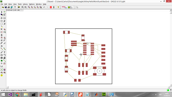
The yellow line between pins are the connections. The first job is to arrange the components for the connections to be as direct as possible, trying to minimize the yellow lines intersections. For doint this we use the Move option, but in some cases we will need to rotate the element. For that we use the rotation button and it works the same as the movebutton.

The arrange elements will see like the following image:
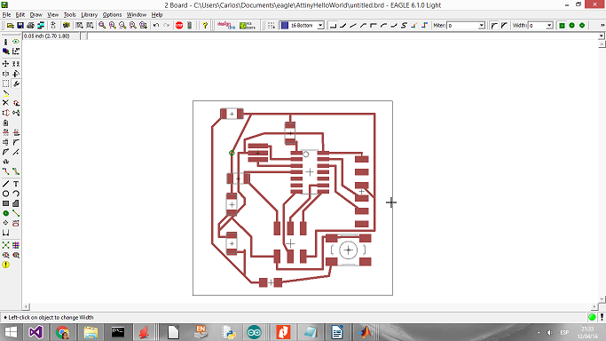
For connection use the "route manually" button or the autoroute option. In the first case the procedure is the same as the connection at the schematic window. The only consideration is that two different joins cannot intersect. In the case of autorouting, the software will joing the pins by itself. It usually works smoothly unless there is to many yellow lines. In that case is better to just use the manual routing.


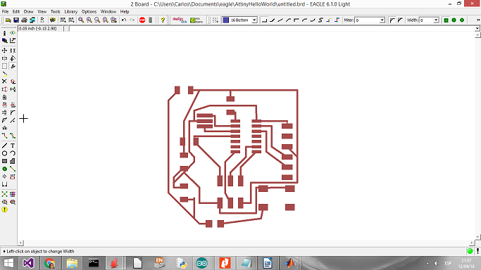
At the end we have the following:
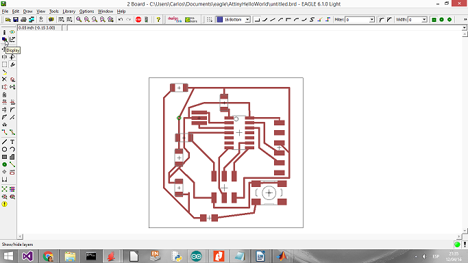
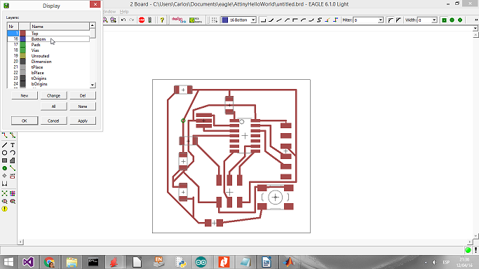
To export the image we need to hide some layers. Each kind of element inside the software have an specific color. If we want to hide all the elements from one color we just press the "Show/Hide layers" button and select which one to hide. We hide all the colors except the red one, which is for the traces.
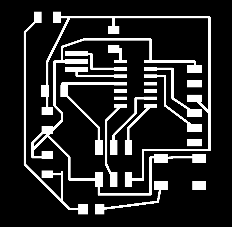
Finally, to export the file to PNG format, go to file -> Export, and click over the image option.
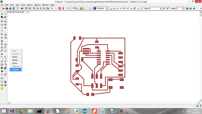
Check the Monochrome box, change the resolution to 600 dpi and select the where to save the picture. Voila! We end the procedure this time.
Files used in this assignment.
At the end we have the following:
Also, it shows were VCC and GND are found in order to add the button and led required.
Download all the files from here.