Computer-Controlled Cutting
During this week assignment we had to use computer-controlled cutting machines. It means that for the end of the week it is needed to learn how to use the laser cutter and vinyl cutter. Because I am currently working in Fab Lab ESAN, I have used before the laser cutter. But, in the other hand, the vinyl machine was still a mystery to unravel...
Battling Ubuntu for Unraveling a Mystery
The first step for using the vinyl cutter is to have a design to work with. I drew a minimalist owl face using Inkscape program.
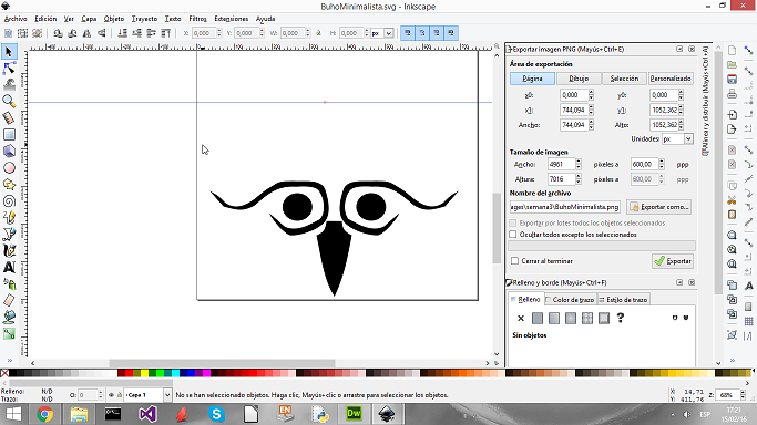
The file was saved as ".svg" and also exported as ".png" ( mynimalistic owl files ). Up to this moment the assingment have been easy. But, nothing good last for long and the real deal started: open the vynil cutter driver in Ubuntu. I will explain my situacion for those who don't know me... I have tried several times to be friend with Linux, but for some reason it doesn't like me. If the mouse can fail, the program crash and the monitor turn off, it will happen for sure. But I, in an attempt of ereasing every affront of the past, approached to it waving a white flag... The procedure followed for using the cutter is:
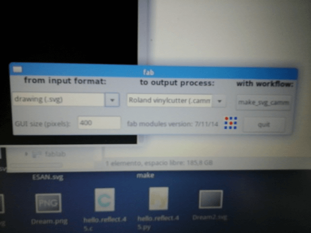
1.- Open the command and write Fab. Fab Module window should open.
2.- Choose the input format file. In my first try I used the svg file.
3.- Choose the machine that is going to be used. In this case I selected the Roland vynilcutter. Press make_svg_camm button.
4.- Upload the file and press the button "make.path". Check that the image is correct.
5.- Change the force to 120. Left the rest of the parameter at their default value.
6.- Press button make.camm
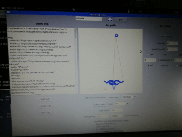
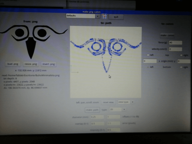
The procedure is simple, but for some reason the svg file upload wasn't like the original, showing that one of he owl eyes was not in the correct place. Fortunately, I had the png file, so I repeat the last procedure changing the format file to png.
The next step is to paste an adhesive paper to the cutten figure for transfering the picture to the surface where it is going to be pasted.
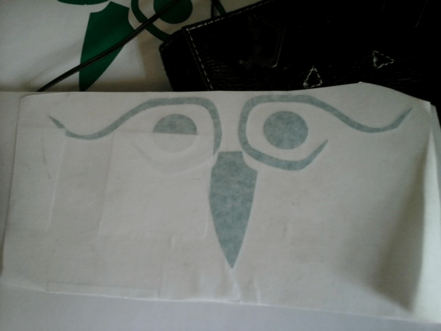
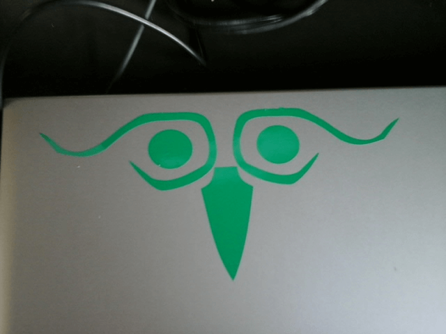
The final product is shown below, pasted over my laptop.
Bending Surfaces With Parametric Software
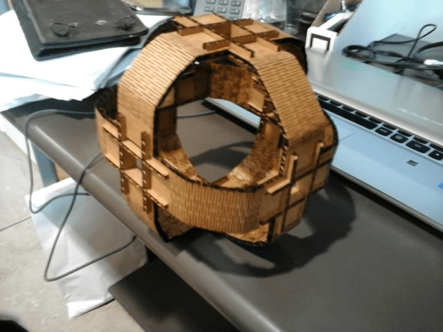
The first time I went into a Fab Lab I saw surfaces with wierd patterns that help bending the structure. For this assignment I tried to do something similar by creating an sphere made from cardboard. The design was done with Onshape, a parametric online software for design.
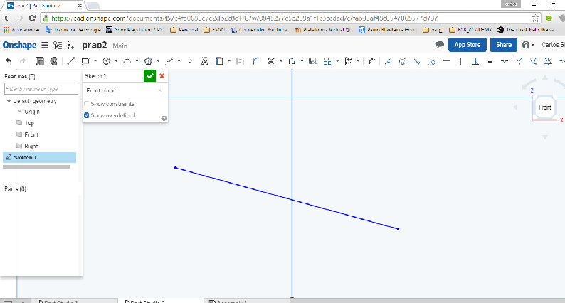
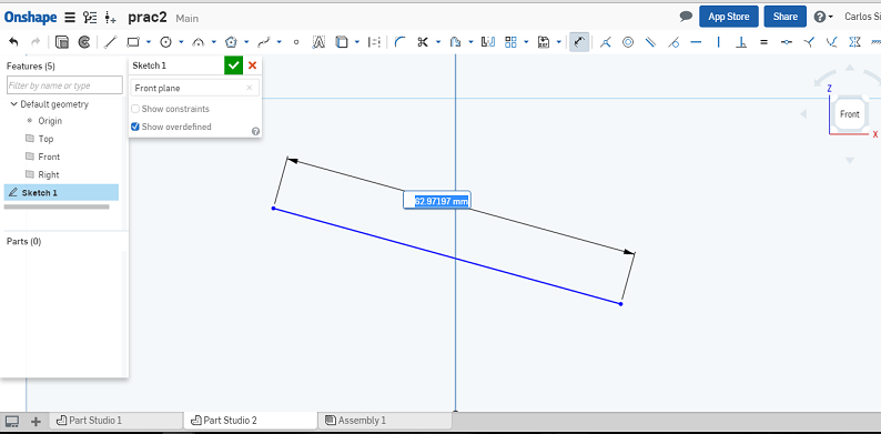
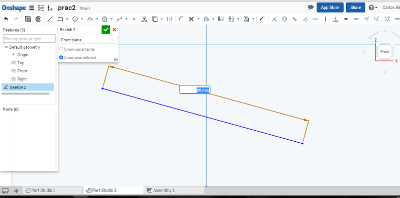
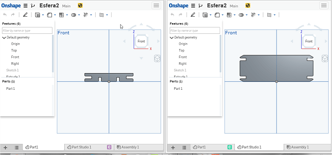
The first design was done thinking on the complete surface of the sphere open.Onshape helps to draw line with specific lengths. For exampe, in the followings photo it can be seen how a line of an unknown lenght change it size to 50 mm using the "Dimesion" tool.
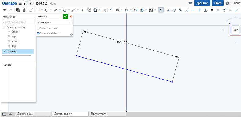
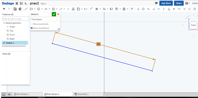
Besides being able to establish measurement to the lines, the software can stand relationship between lines, like for example perpendicularity, parallelism, tangency, etc.
I was not happy with the design beacause it uses to much space in an unefficiente way.
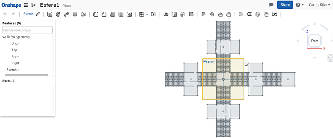
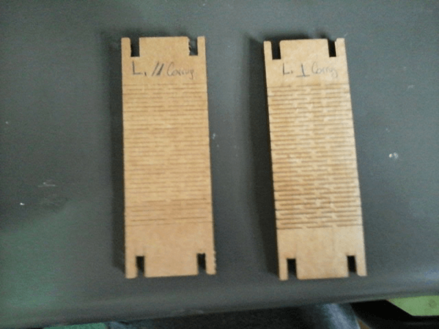
A friend of mine saw the model and gave me good advices. Instead of having one big piece that will join together through small pieces, the structure could be made using just two kind of pieces. The design is not only way more easier to draw, but also have a good control of space, minimizing the left overs of the cardboard.
The parameters used for the laser cutter were
Speed: 37
Power: 98
Frequency: 500
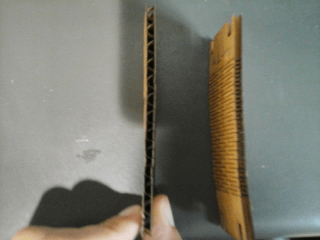
A test was done to see how important the orientation of the filamentos from the cardboard are and their signficance in the mechanical properties. It was found that when the lines are perpendicular to longest dimension of a piece, it is more rigid. It include the case where cuts for bending properties are done.
The final product, the sphere, is shown in the next image.
Download all the files from here.