Week 4
Electronics Production.
This week we will make ISP programmer that we will use in later weeks for programming many chips.
This week the focus is on the production not the designing, so i'm going to use FabISP design to make my own programmer.
Cleaning the bed is important, because any remainants will lead to a bad finish and break the endmill.
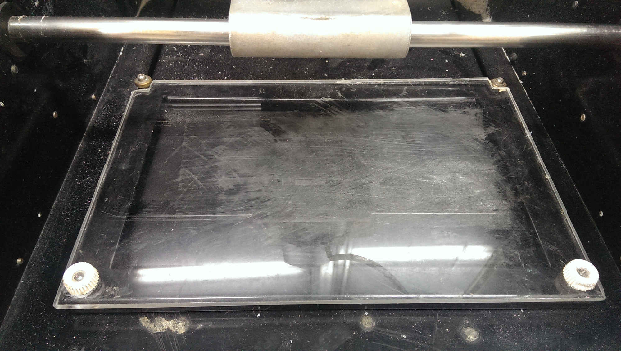
To fix the board, Add double face tape. The nice thing about the tape is that it's easy to remove and fix the board really good.
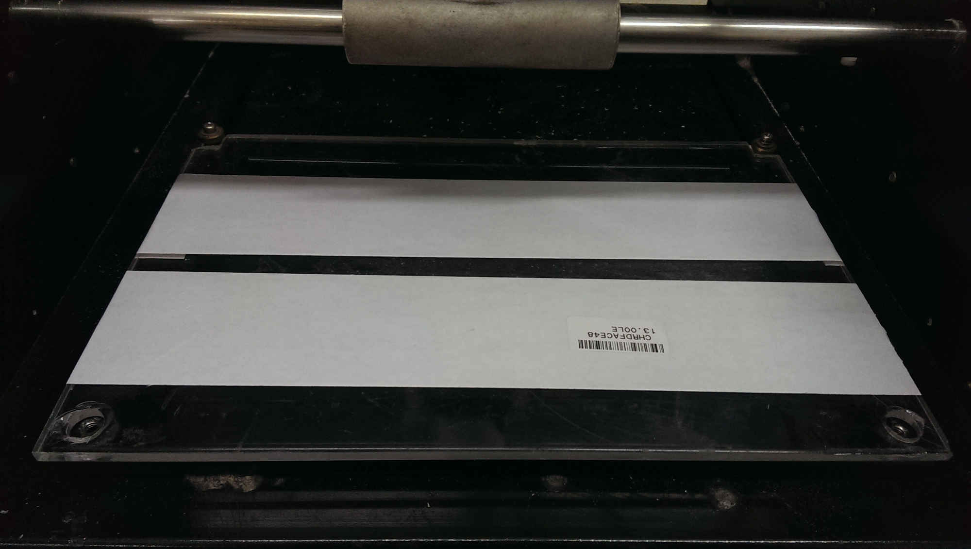
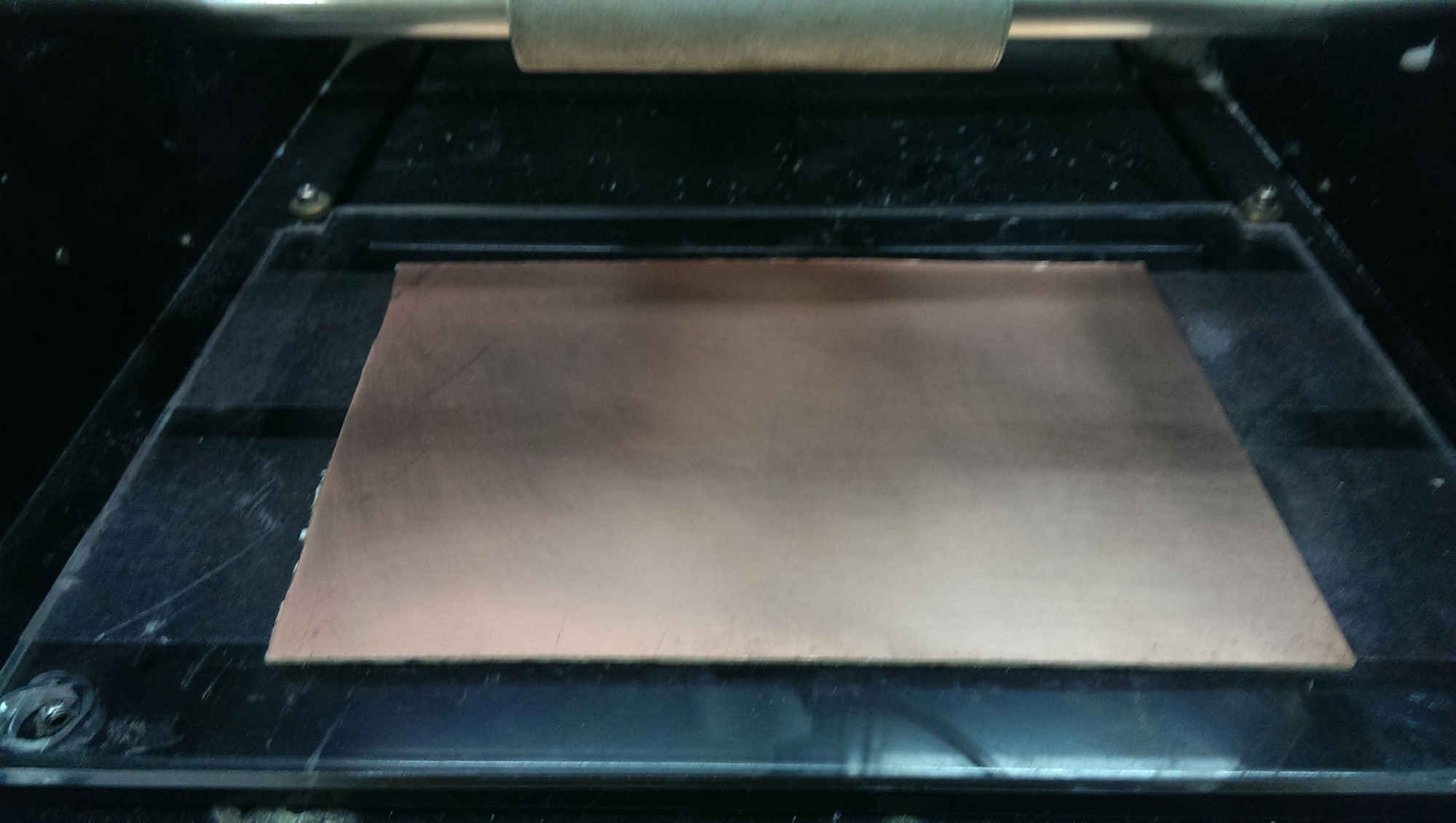
Now fix the board and we are ready to start.
Fab Modules is what we will use to generate the path for the machine and send the machine the RML file that contains the instructions to produce the circuit. There's two versions of fabmodules, the old one you have to compile it on your laptop, and the new one is using HTML5 and a webserver that is running on your laptop. I've tried both of them and i have faced some issues with the HTML5 version that often resulted in breaking many endmills. However i'll cover the process i followed to generate the rml and send it to the machine.
Fab modules HTML5 works by sending the commands to a webserver running on the computer connected to the machine so to start the webserver you open a terminal and go to the directory of fabmodules and write
sudo npm start
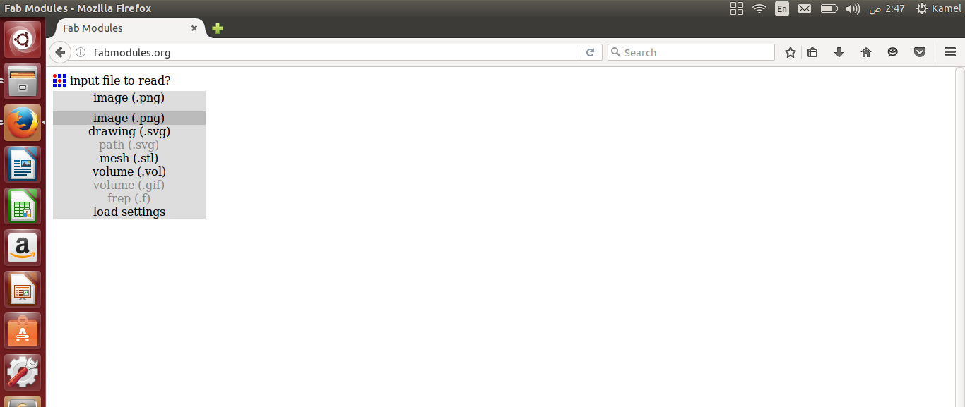
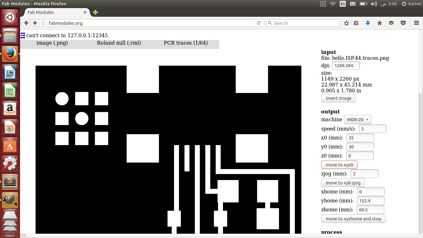
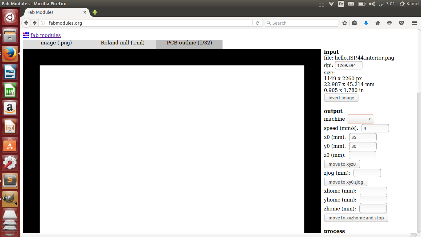
So the webserver is now running and listening on port 12345 on your local machine. Now we can use online fabmodules from here or write localhost:12345 in your browser. Anyways, you will see this webpage.
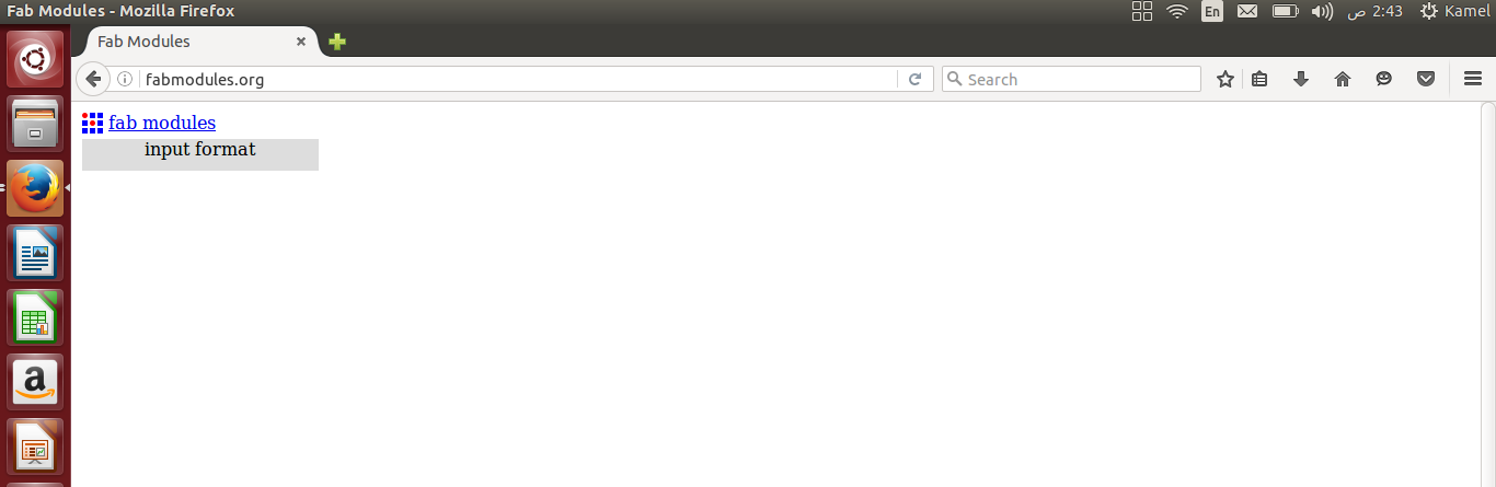
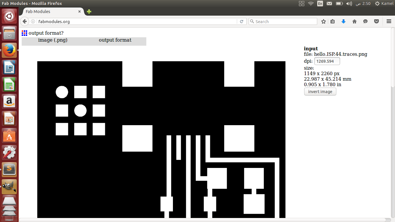
Load image from input format choose PNG then select your PNG file.
Choose output format to be Roland mill (RML)
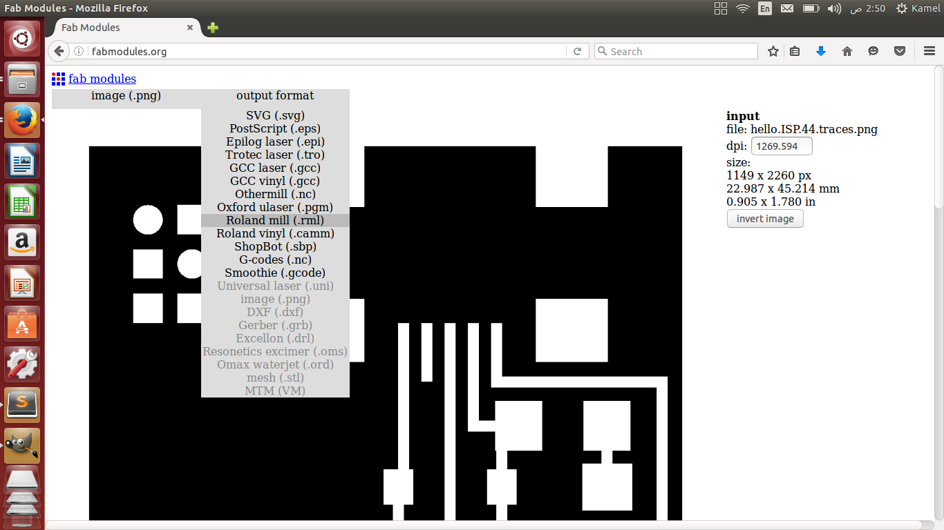
Choose process PCB traces (1/64)
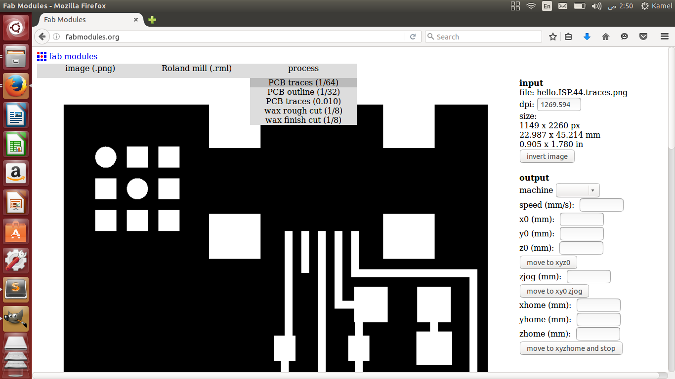
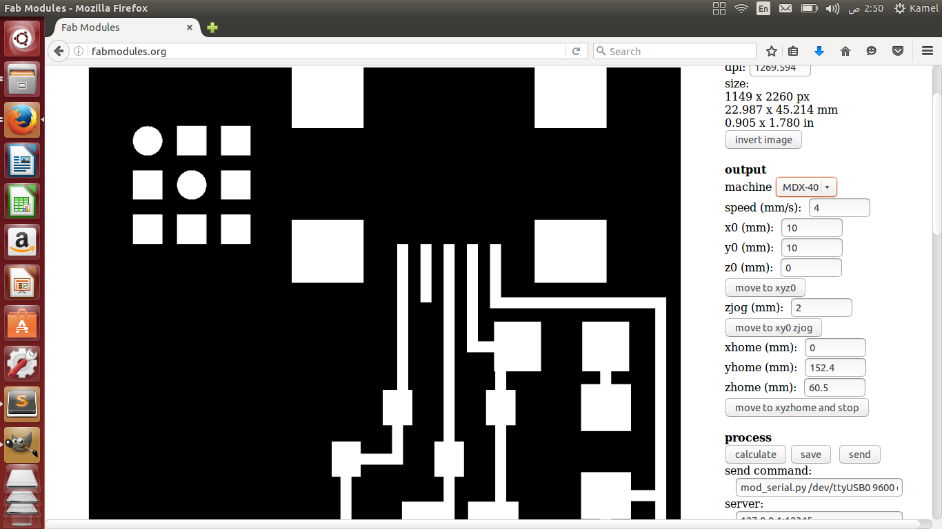
From machine i selected MDX-40
Move the head to the edge of the copper sheet and zero the Z-axis
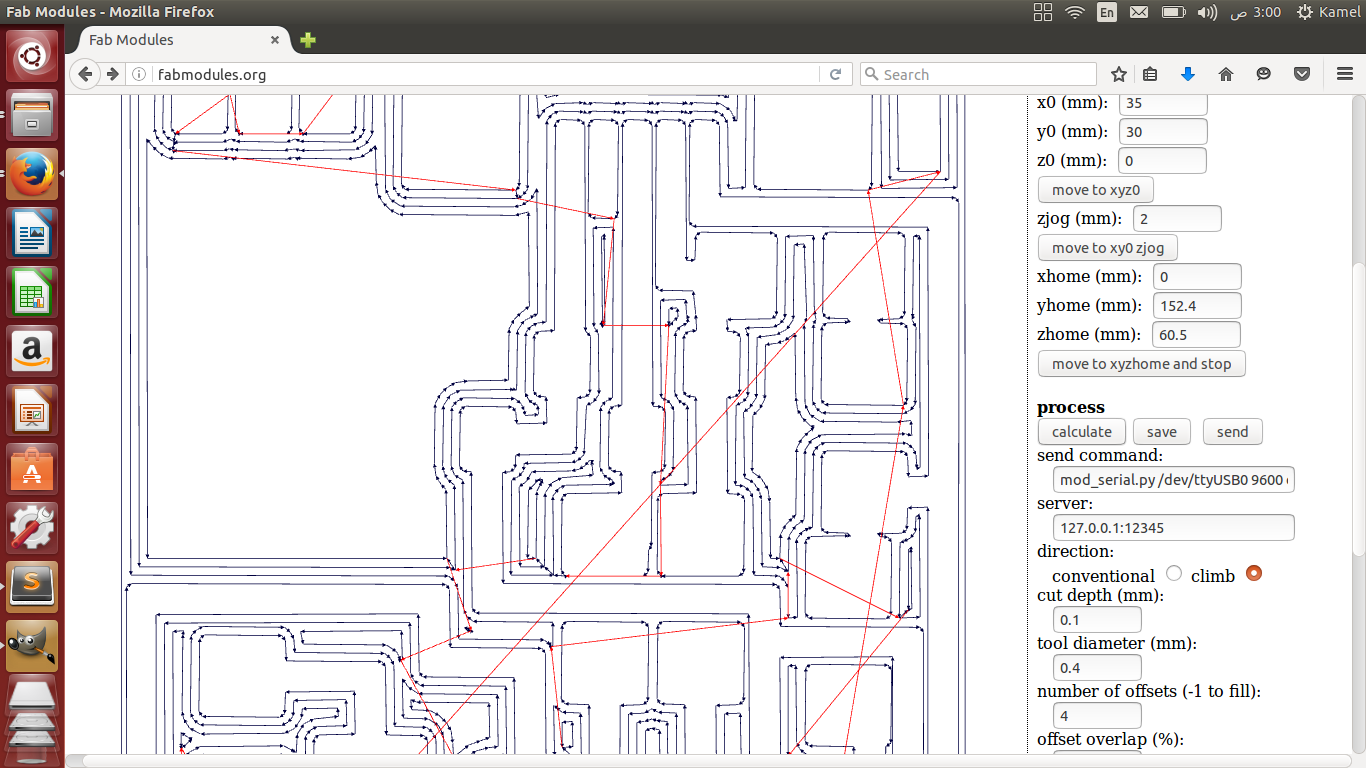
I entered offset 4 to clean the area around the USB
Click on calculate to generate the toolpath for the machine then send to send it to the machine.
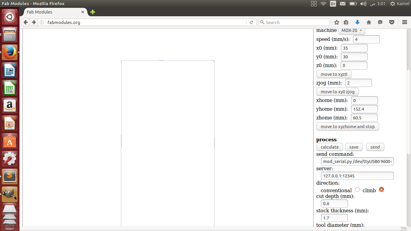
To cut the board will make the same thing, but i choose process PCB cut (1/32) and changed the endmill.
Zero z-axis and calculate then send the rml to the machine.
To start Fab Modules, open a terminal and write "sudo fab" and enter your passaword.
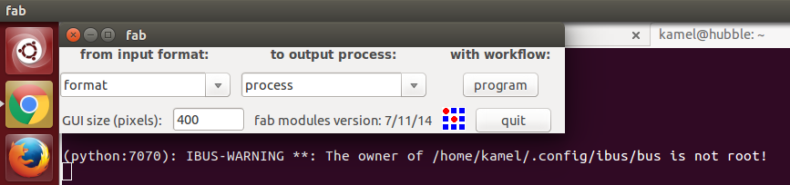
Choose Image PNG as input format and Roland MDX-20 mill as ouput, then press Make_png_rml.
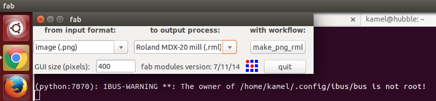
We will setup the different processes here and excute.
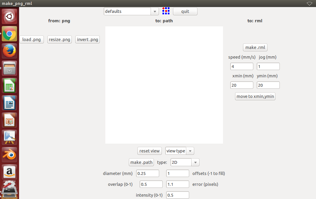
The steps of working is:
1- Load PNG image.
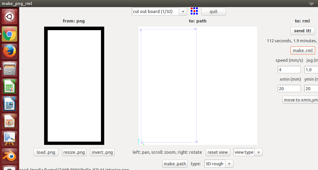
2- Select process, milling or cutting.
3- Generate path.
4- Edite the offset.
5- Set x,y coorinates.
6- Set engraving speed.
7- generate RML.
8- Zero the machine Z-axis.
9- Send the RML to the machine.
1- Load PNG image.

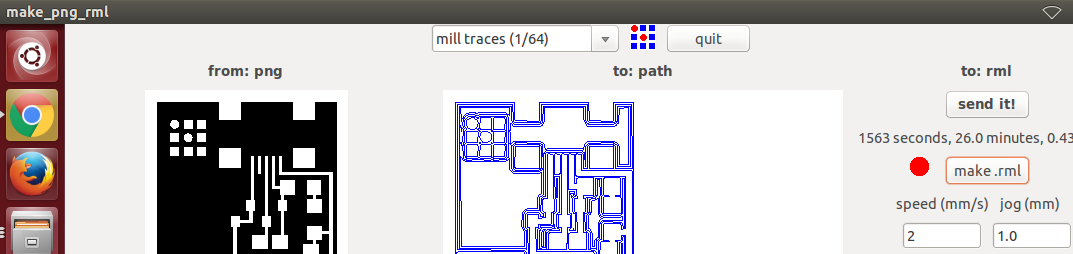
2- Select process, mill traces (1/64).
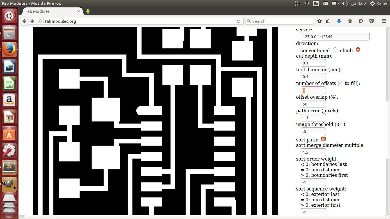
3- Generate path.
4- Edite the offset.
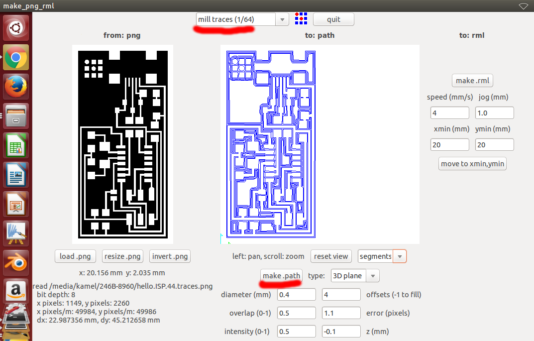
You can change the offest. The offest is how many mills you want to make around the traces. Higher offset makes it easier for soldering but takes more time. I usually use 2 and up to 4 if necessary.
5- Set x,y coorinates.
6- Set engraving speed.
The engraving speed is a critical parameter, because if you cut with high speed you will end up with ugly rough traces and probably you will break the end mill. 4 is default but i prefer to make it 2 for smooth finish.
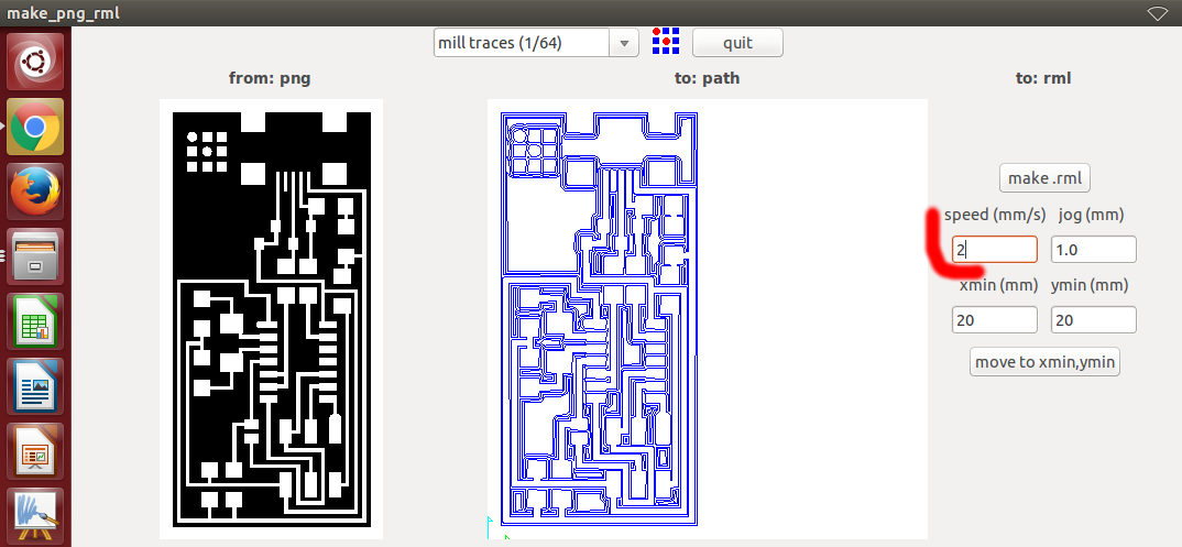
7- generate RML.
The RML which is the actual instructions that will be sent to the machine. The software will tell you the estimate time for the job.
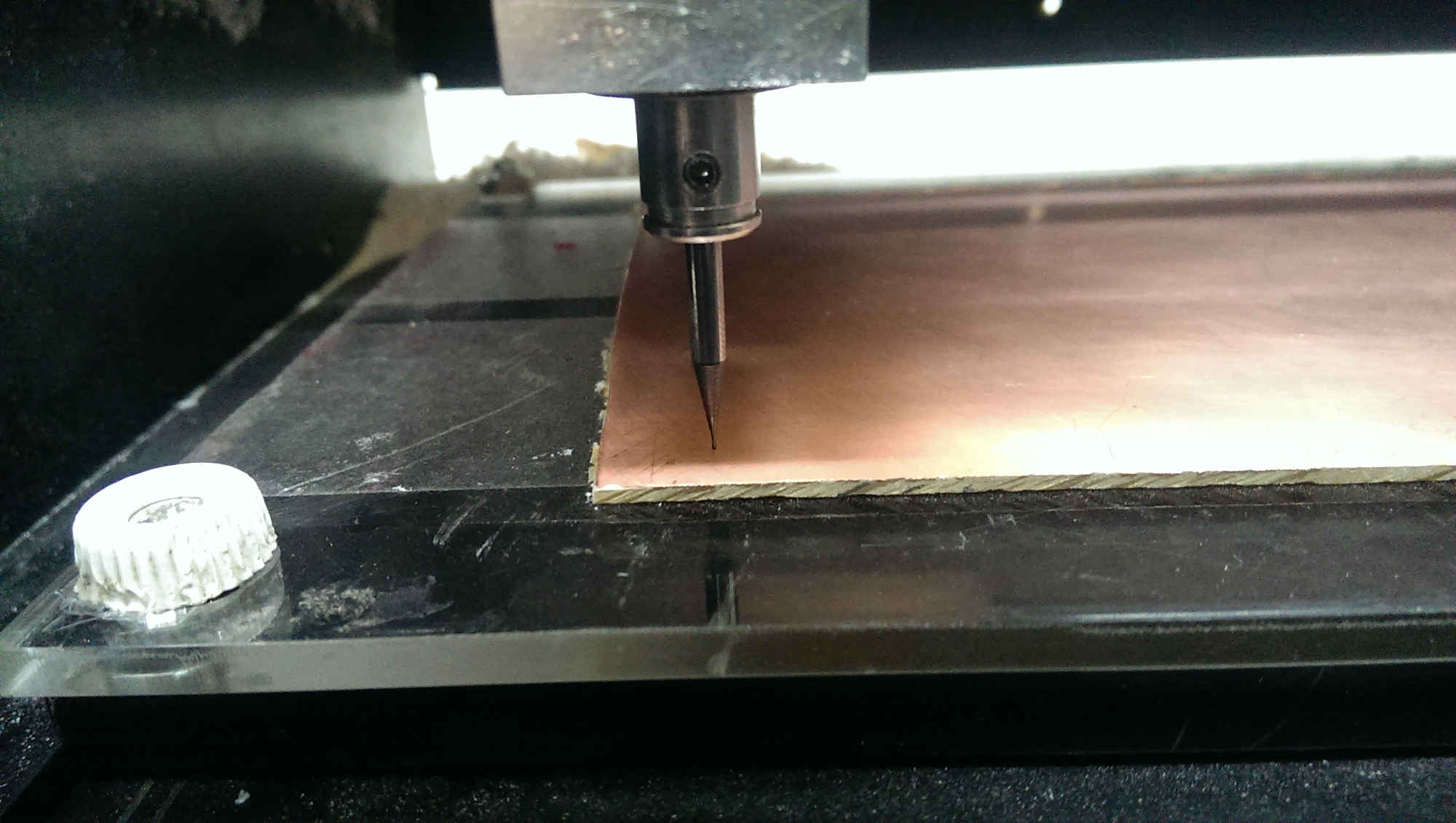
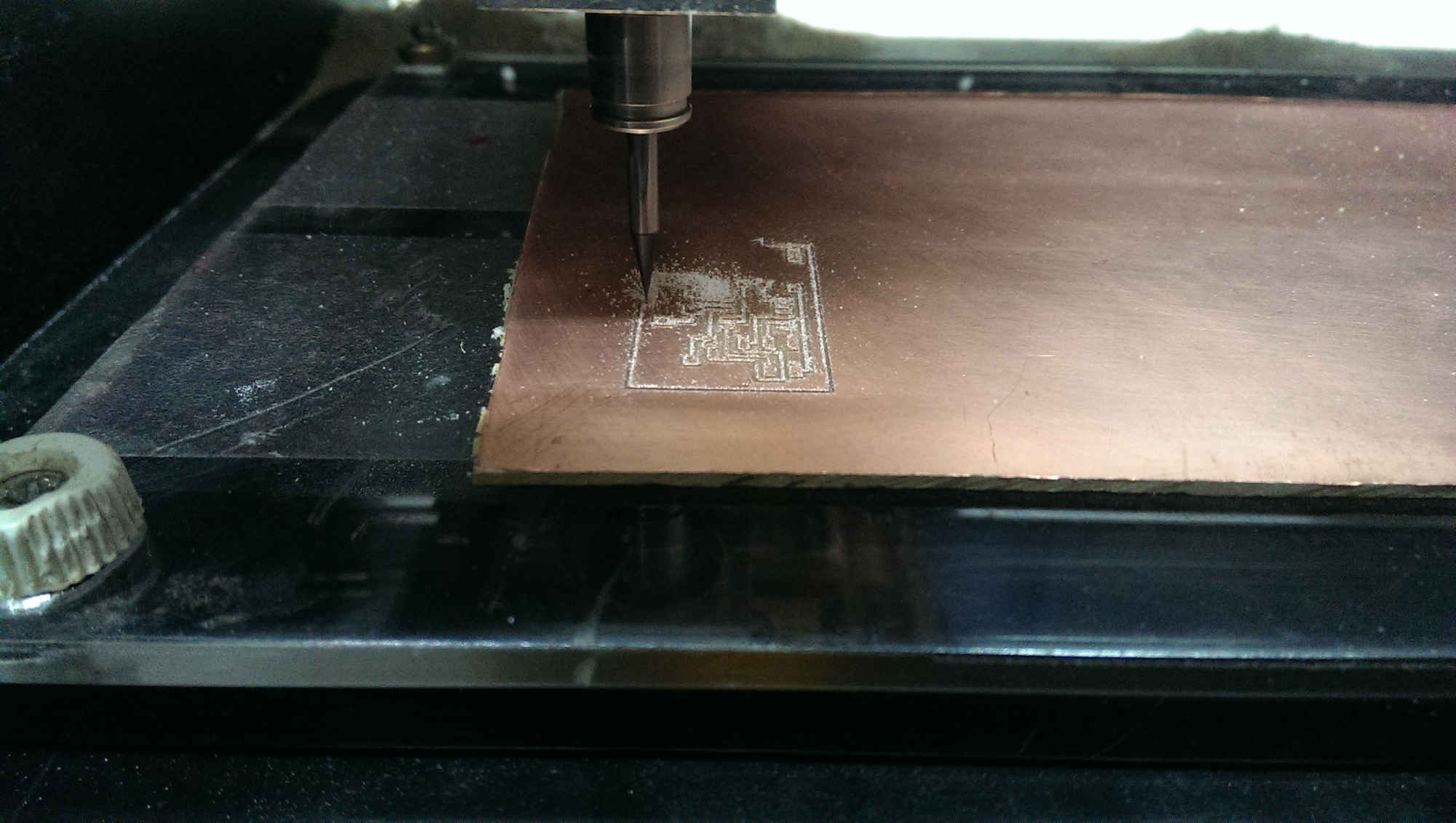
8- Zero the machine Z-axis.
This step is really important. You need to set the end mill to be just touching the board. The way to do so is pressing down until the endmill is really close to the board, then loosen the screws and make the endmill touches the board, then tighten the screws again.
9- Send the RML to the machine.
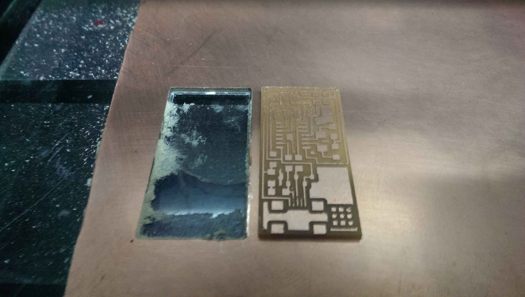
The machine will start millling your Circuit. Enjoy watching it.
To cut the board we use different endmill but you will go though the same steps.
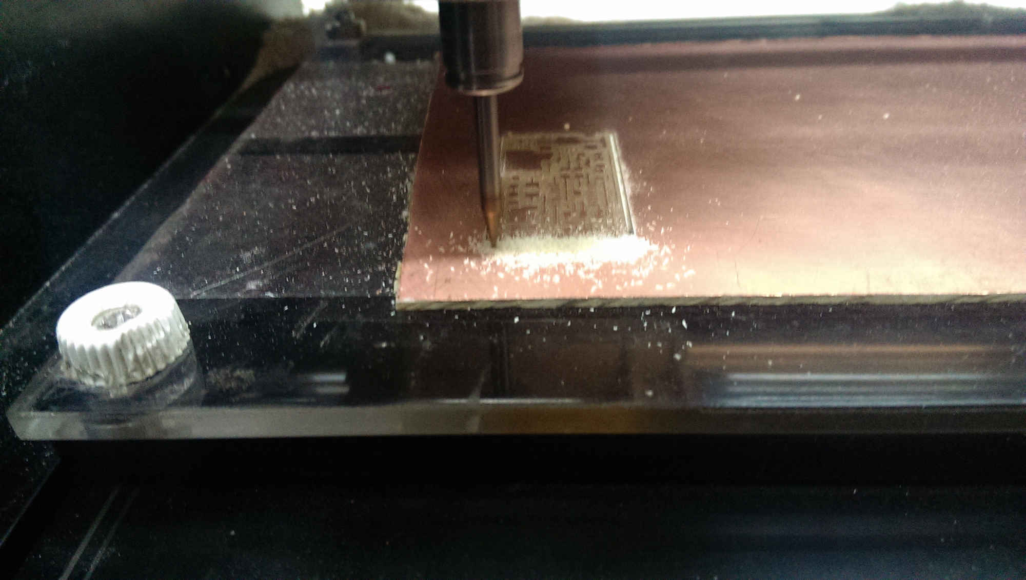
And after cutting.
Clean the board with water.
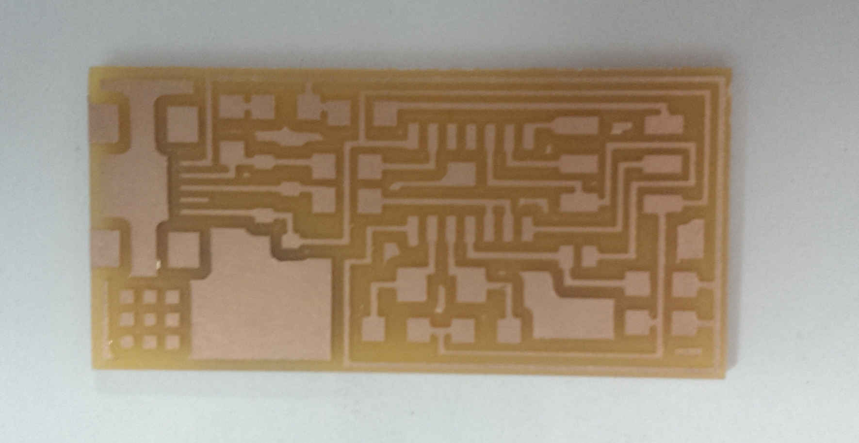
Now we are ready to solder the components.
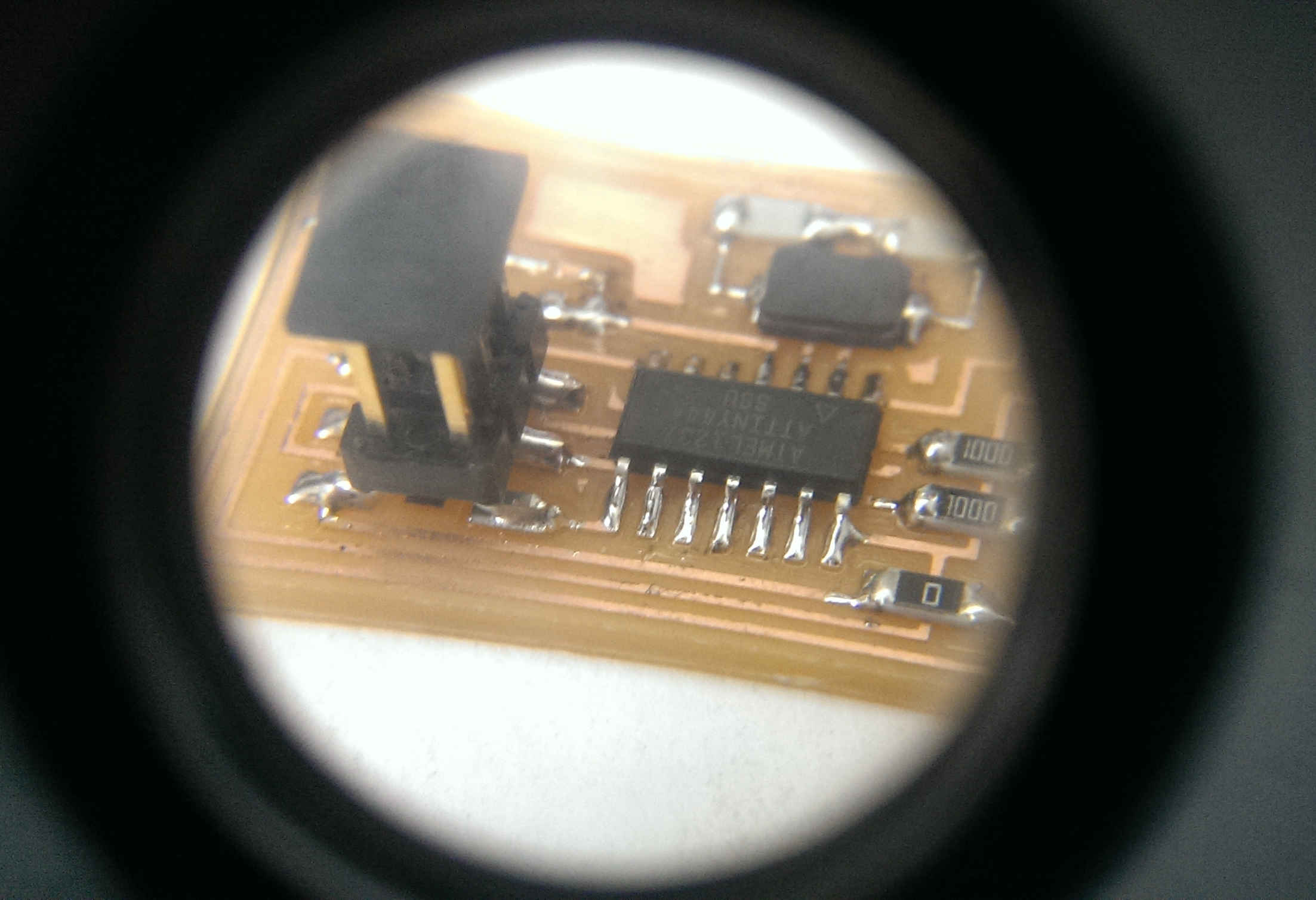
Start soldering components from centre to border and from smaller to bigger.
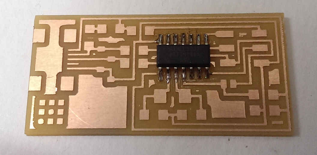
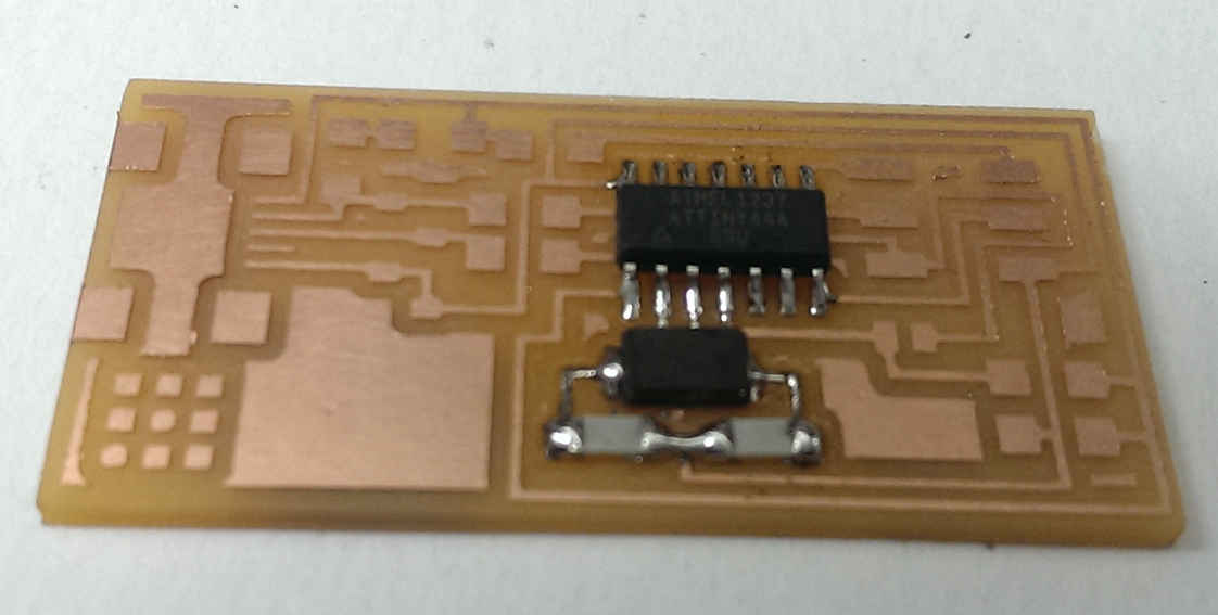
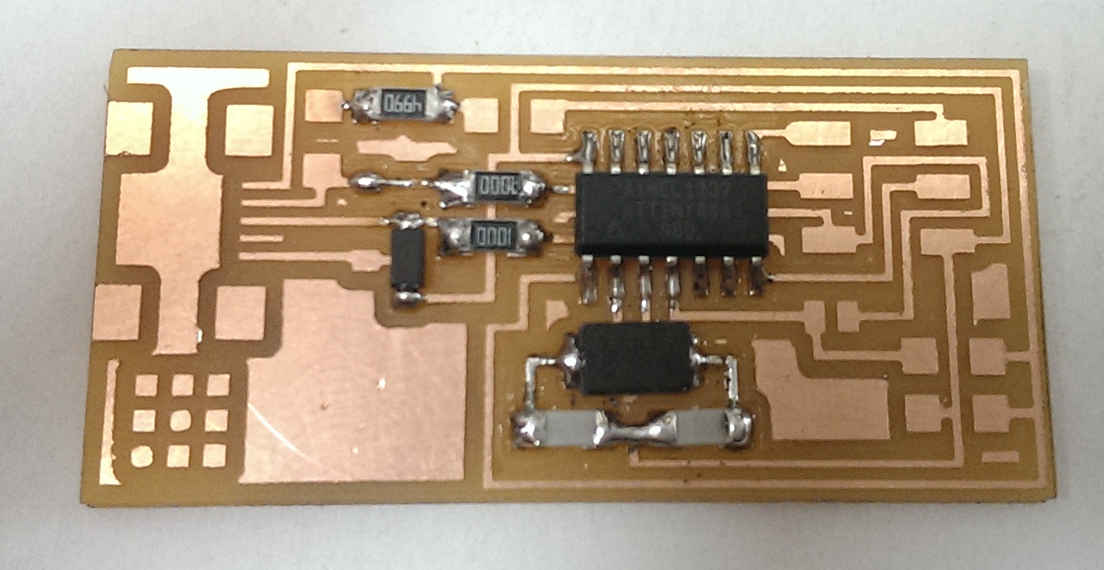
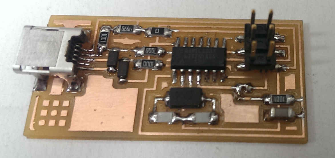
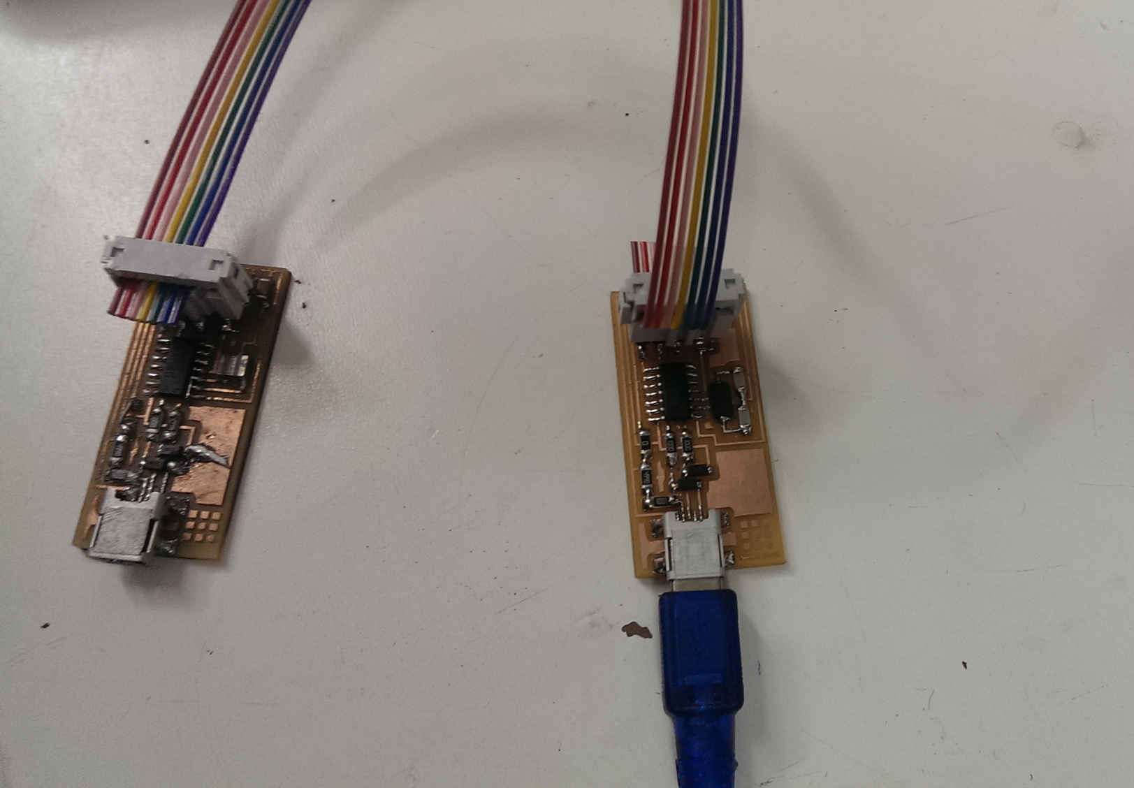
Frankly it doesn't look bad so it's not bad as Neil said.
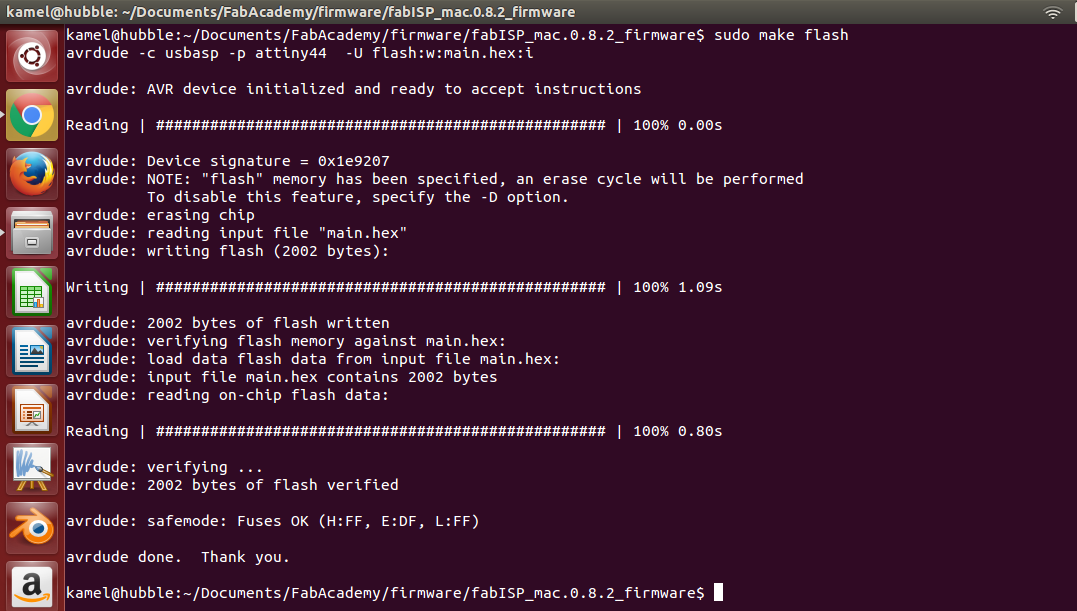
To program it i downloaded firmware from classes archive and used avrdude and another FabISP as programer.
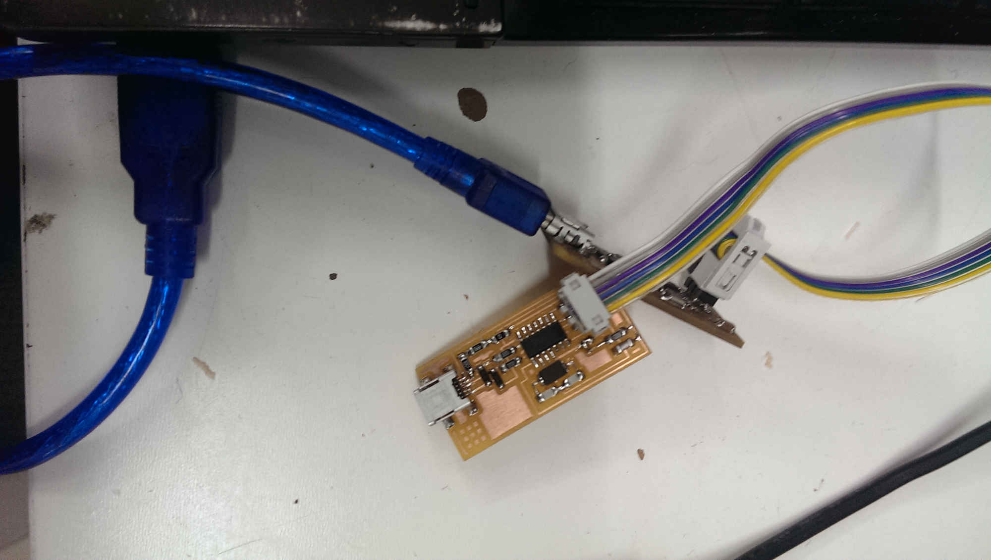
From a terminal i make the hex file and uploaded to the flash.
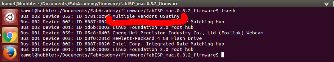
To verify that it is working i listed all usb devices and found it.
The last thing is to Desolder SJ1 and you are ready to use it.
I also used my programer to program my friends circuits.
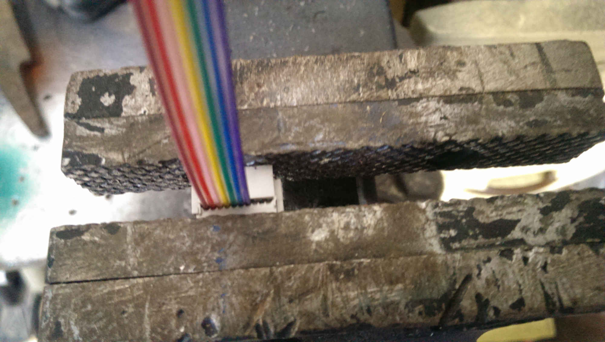
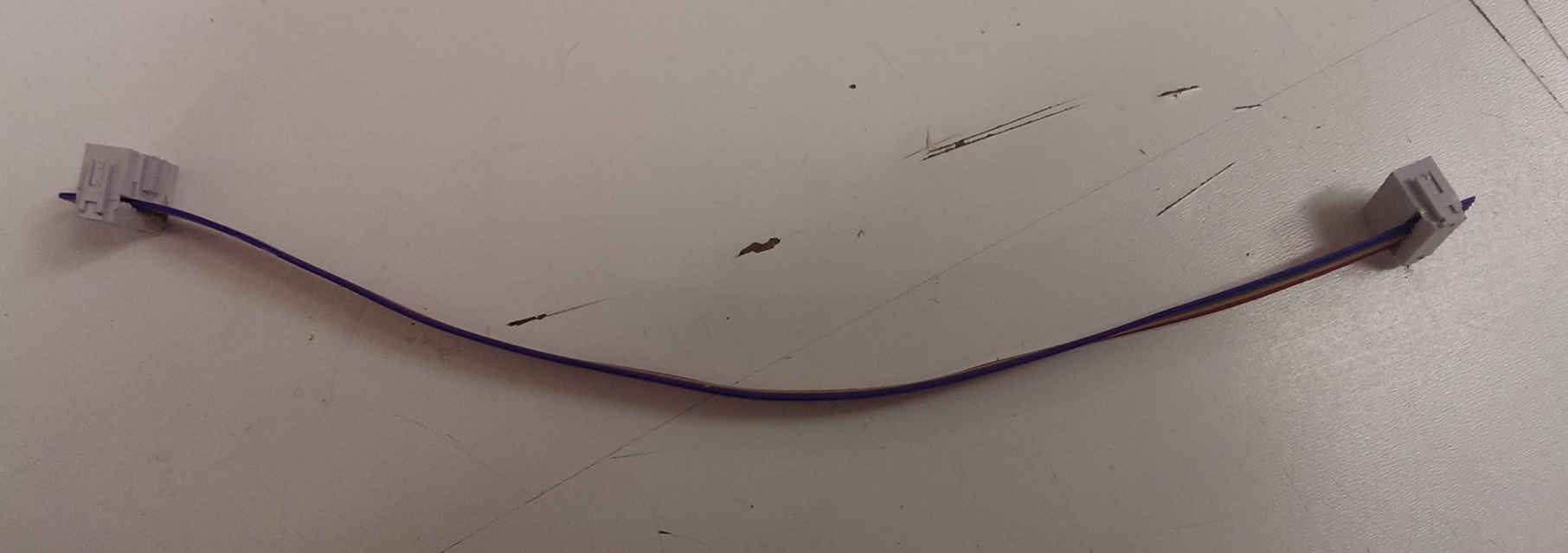
Made my own ISP cable using IDP connectors and ribbon cables.
Happy Milling, Soldering, And programming.