Week 13
Output devices.
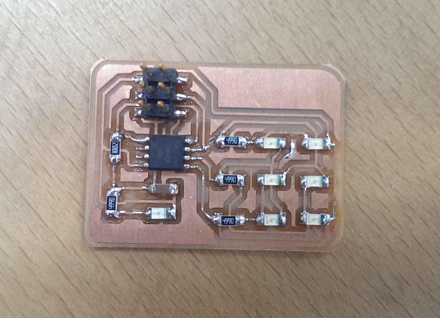
The assignment is to add an output device to the microcontroller and program it to do something. I wanted to make a led matrix using charlieplexing technique.
The idea is to utilize i/o pins to control leds more than its number. Each pin can supply and sink current. We use one pin to supply and as many pins as you have to sink current. So in my case i will use only 3 pins to control 6 LEDs.
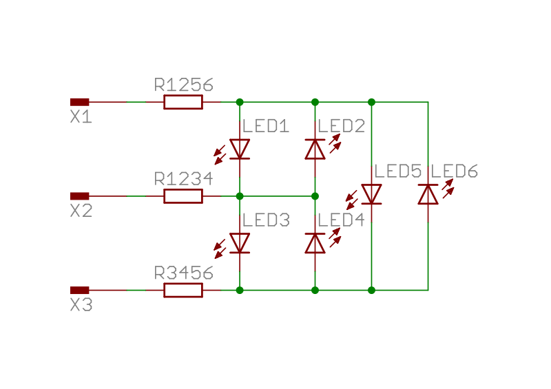
I'm going to use attiny45 microcontroller with 6 LEDs and power on LED.
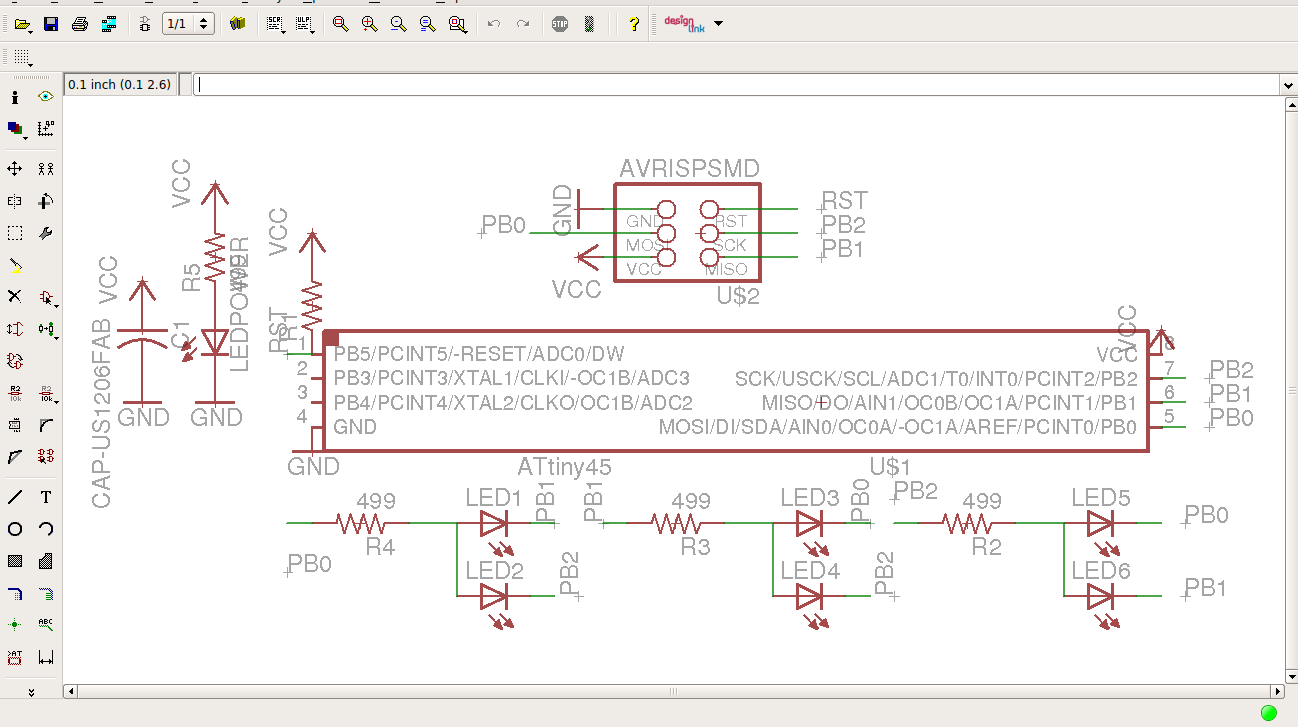
Download the eagle files.
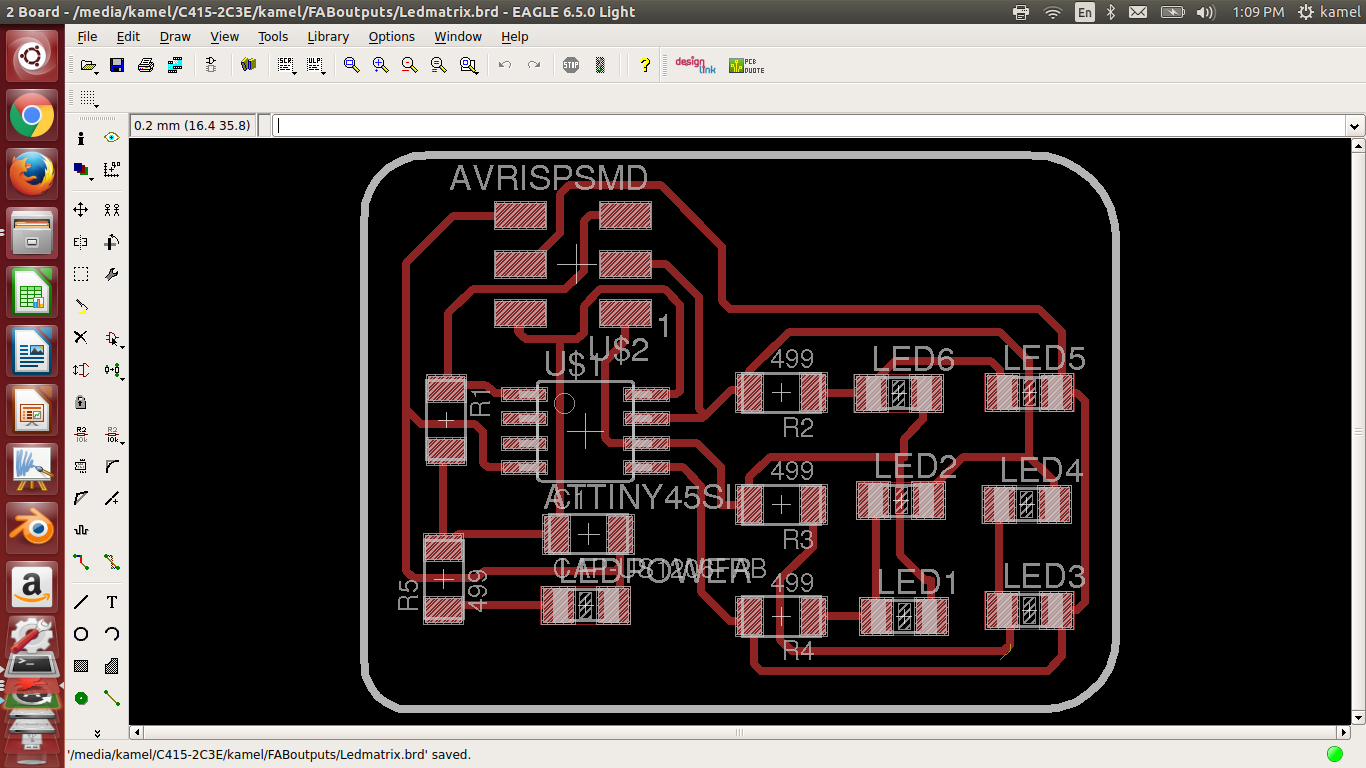
ledmatrix.schDownload the exported images
ledmatrix_traces.png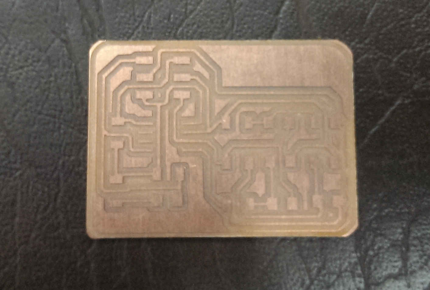
The code is select a LED and set the anode port pin as HIGH and the cathode port pin as LOW.
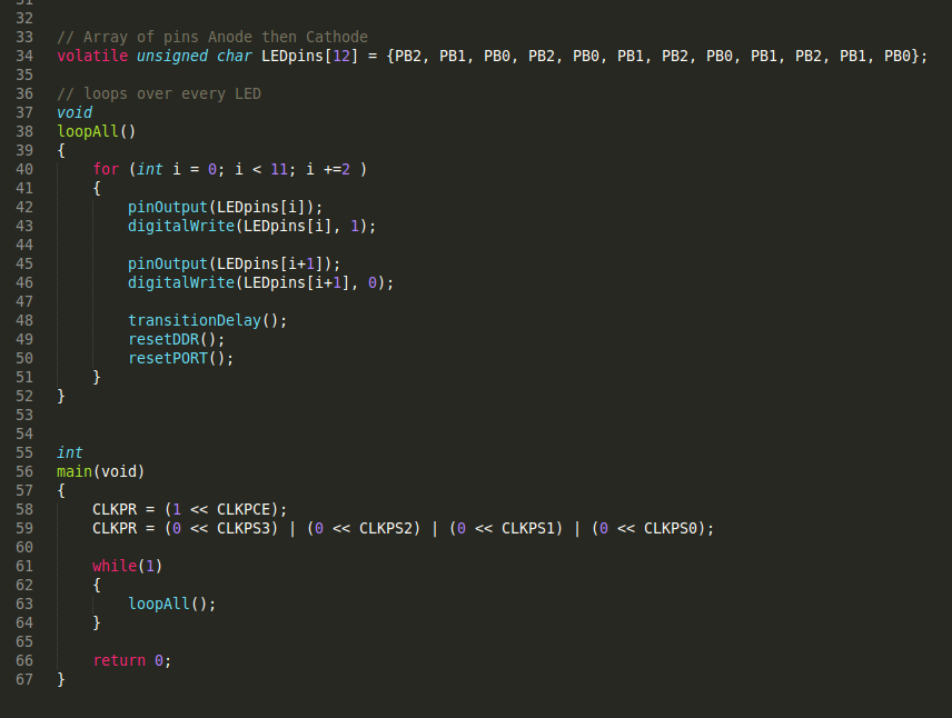
Download the source code:
ledmatrix_V1.cCompile the code by writing make -f ledmatrix_V1.c.make
Upload the HEX file by writing make -f ledmatrix_V1.c.make program-usbtiny
It worked as expected. Here's a video :
Fab Academy - Week 13 - Output devices from Mohamed Kamel on Vimeo.
I wanted to be able to display any number of leds at the same time. In the previous example if i decreased the delay enough between every led, we will be able to see the whole LEDs on. That's because our eyes are not fast enough to catch the change. So i used the same concept to display different patterns.
I setup a simple interrupt for the counter overflow. Everytime the counter overflows i increment a variable when the variable reaches a threshold (a certain amount of delay between every pattern) it switches to the next pattern and reset the counter.
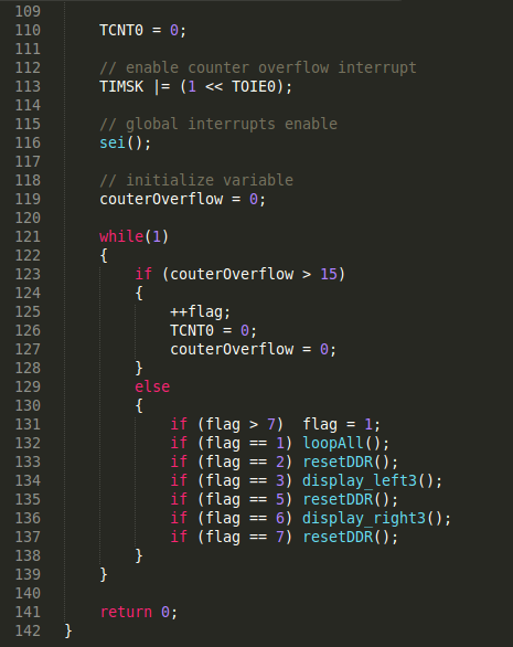
Download the source code:
ledmatrix_V2.cCompile the code by writing make -f ledmatrix_V2.c.make
Upload the HEX file by writing make -f ledmatrix_V2.c.make program-usbtiny
Notice that you can't turn more than two leds at the same time without this approach. But now i can even turn on all of the leds.
Fab Academy - Week 13 - Output devices - LED matrix from Mohamed Kamel on Vimeo.
Thanks for passing by!