For this assignment, I thought I would work towards my Zen Desktop Garden. I wanted to figure out how to output a signal to different LED lights, so I designed a board with three LEDs (red, blue, and green), each with its own resistor. First, though, I needed a microcontoller. I decided to modify the Satshakit board because it apparently can be programmed using Arduino IDE, and with my inexperience with programming, I thought this would be a plus. The documentation that Satshas provided for this board was also quite helpful.
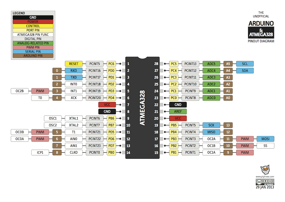
First I started with the original board files, and I made some changes. Since I wasn't going to need all of the input pins on the original board, I changed the design to utilize fewer pins of the ATMega 328p. Using the pinout diagram I found below, I was able to figure out which pin on the processor was related to the number on the Arduino, and that is how I figured out which pins to use and which not to.
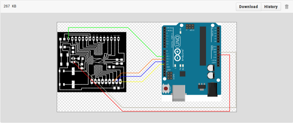
Since I was going to need the Arduino to program my version of the board, I wanted to make sure that I understood how the boards would be connected for programming. That way I double checked that I unused pins were just that- unused.
I also changed the power header from just two pads (onto which one solders wires) to a 2 x 2 header pin. I figured this would be easier to quickly plug and unplug the board.
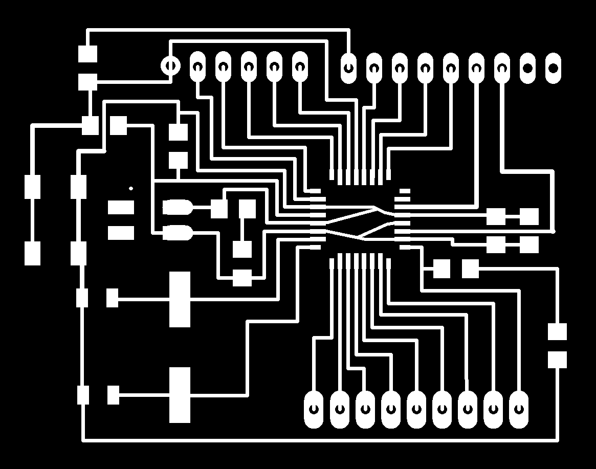
I had to move the button out of the way in order to fit the new header piece onto the board, but I think it turned out quite well.This is what the traces of my version of the Satshakit board looked like.
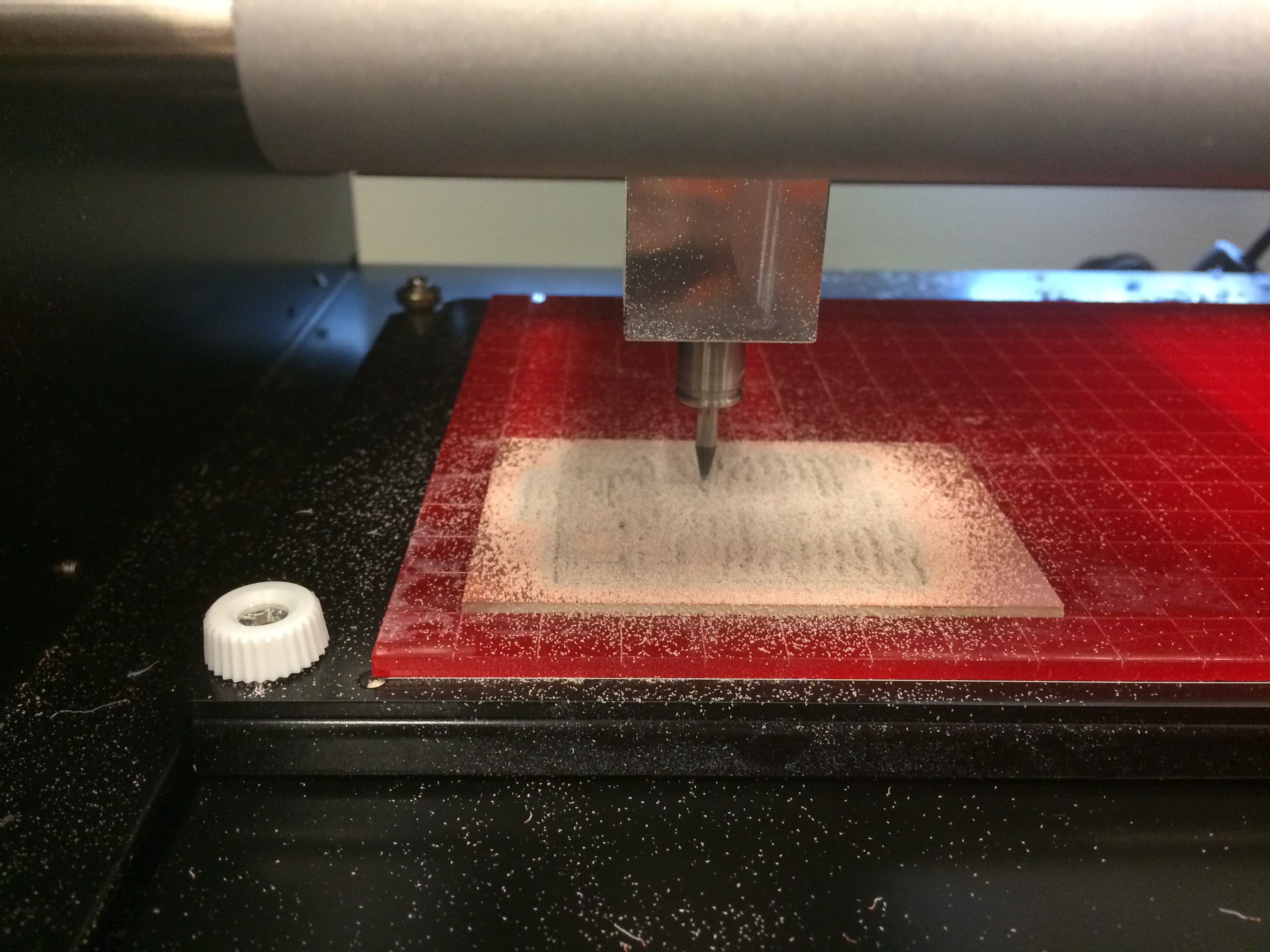
This is a picture of the Modela milling my board.
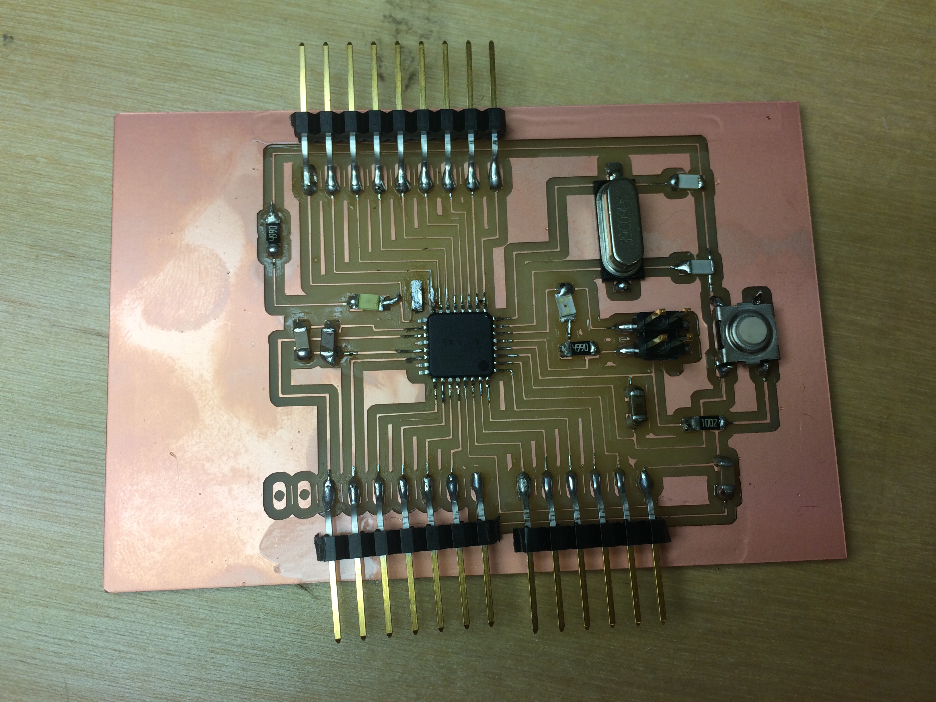
And here are my mad soldering skills (not.)
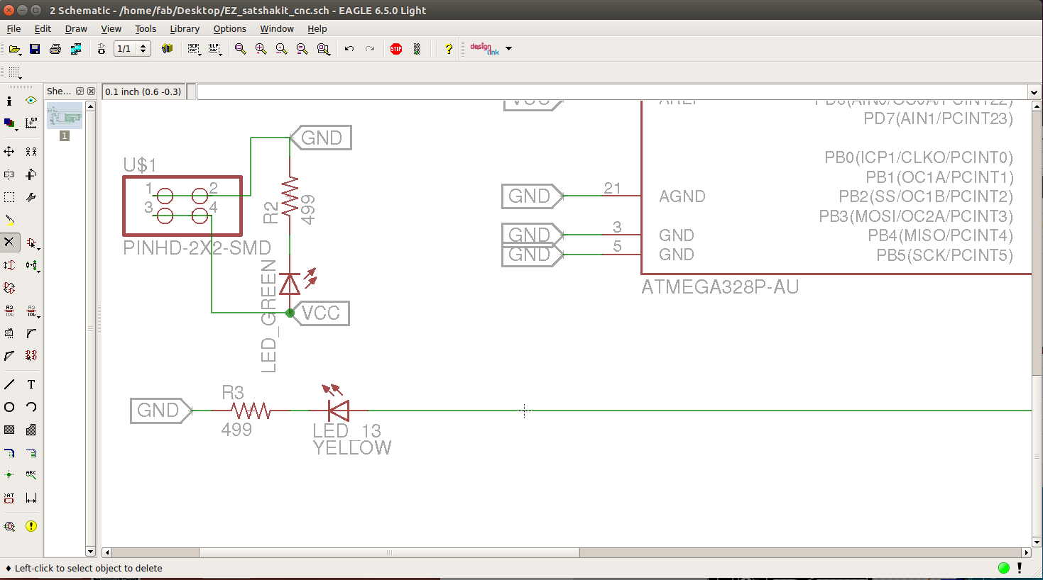
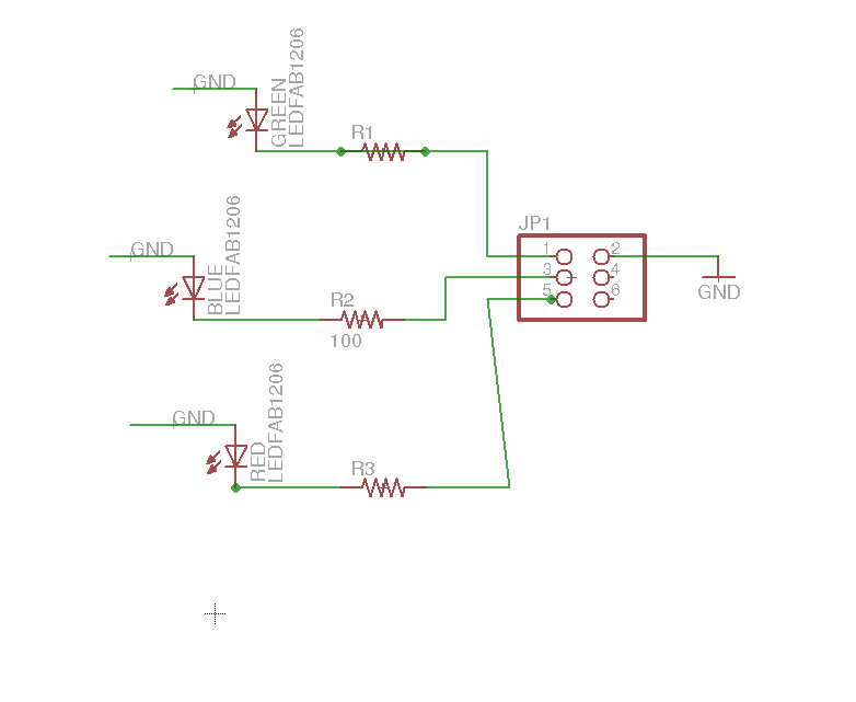
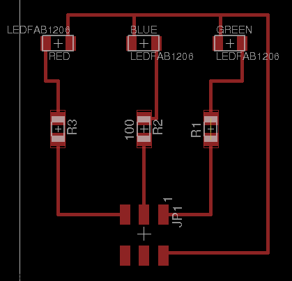
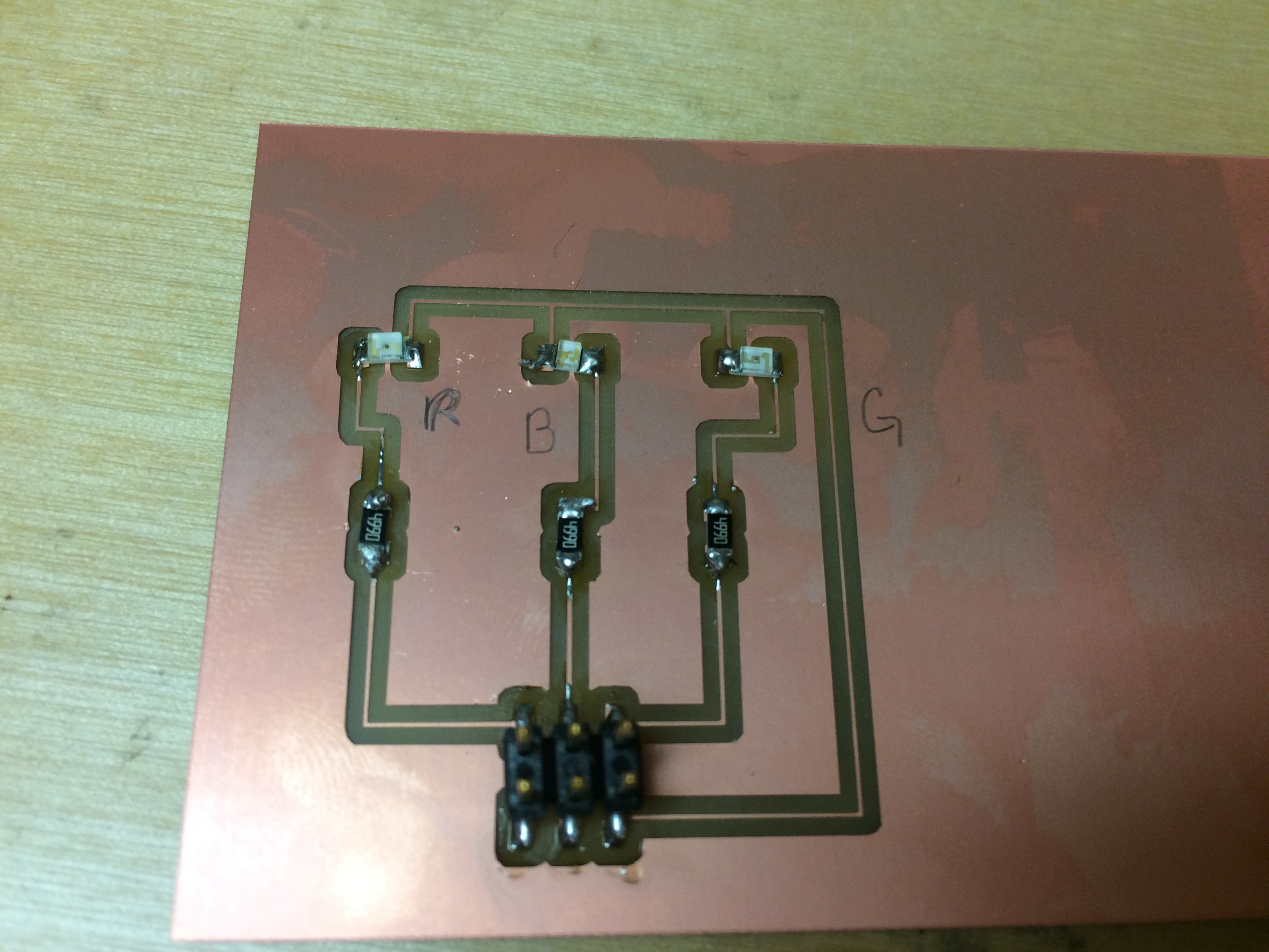
Next, I designed a small breakout board for my LED lights using Eagle. This went pretty quickly, since I am finally getting to know my way around Eagle.
My Eagle files can be found here:
Then, before stuffing the board, I had to figure out what size resistor to put with each color LED. After some internet research, I found an equation, and I plugged in the numbers for each of my colors to find the minimum resistance needed for eah LED:
Resistor Value= (Vsupply - Vf)/If
And, after all that math, I descovered that the closest thing we have in the Fab inventory is 499 Ohm, so that is what I ended up using for all three of my LEDs. It worked fine.
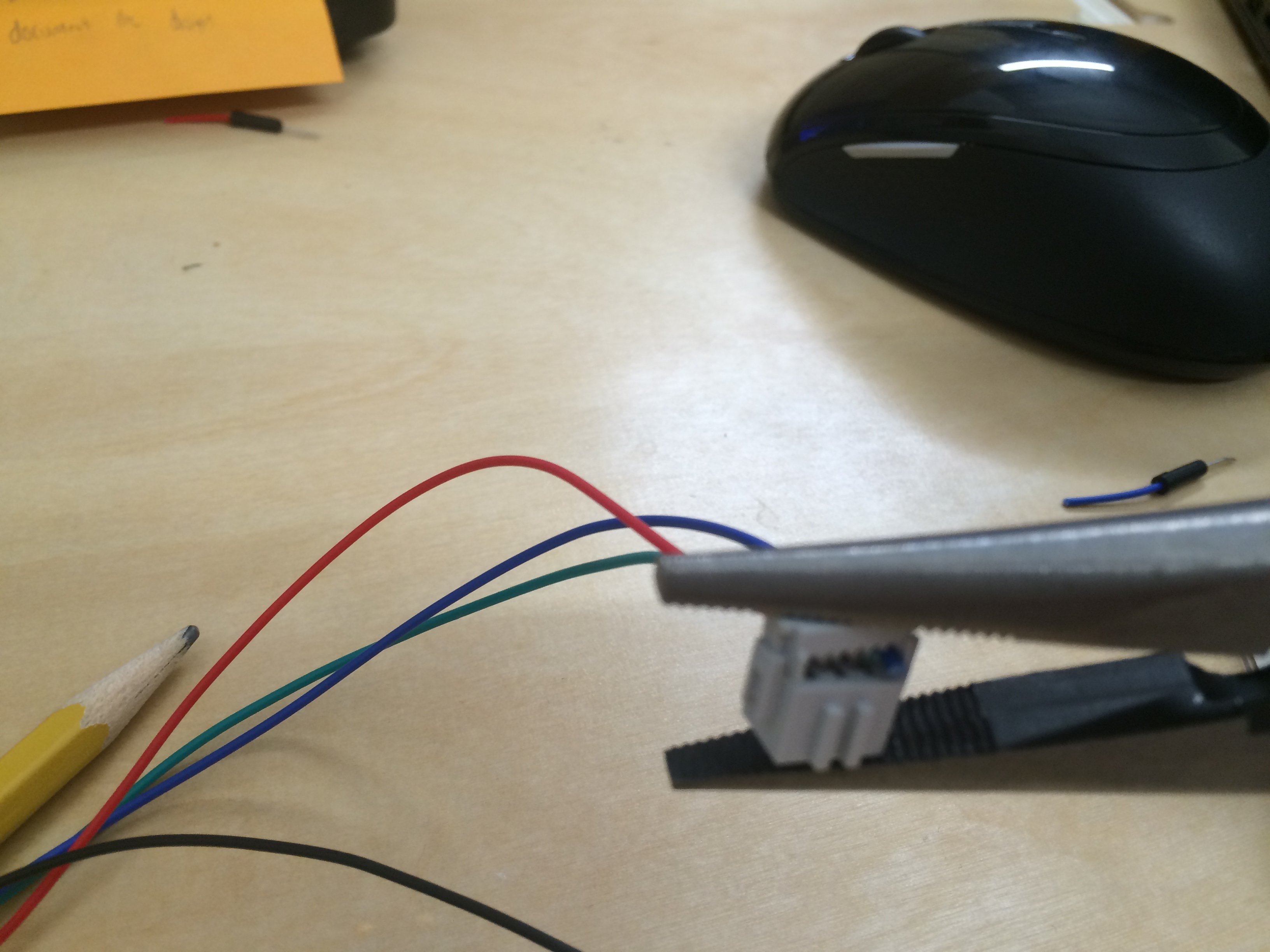
For the pins, I had each LED going to a different pin in a 2x3 header, and all of the grounds going to one pin, so I had to make a breakout cable to interface to my modified board from the LED board that I made. I put the 6 receptacle on one end, plugged it into the board, and then used a voltmeter to test continuity on each color of the cable. Then, I soldered a jumper wire (color coded to make plugging easier) onto the other end of the ribbon cable for the ground, used a 6 receptacle (even though I only needed three), and voila- new one application only cable!
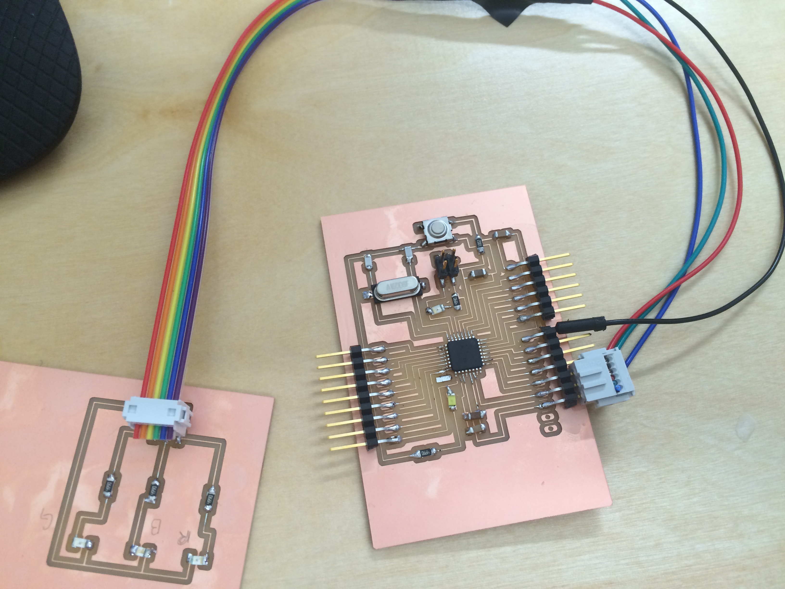
I plugged my leads in and then programmed the modified Satshakit board to take serial input (in the form of typing "r" "b" or "g") and then flashing the appropriate LED.
I found a great example of arduino code that demonstrated the using a switch case. I changed the input in each case.

I also ended up changing the for loop since I couldn't get it to turn off the LEDs. Instead, I just made them blink with the serial input by adding a delay and then digitalWrite(pin, LOW);
It worked great, and below is a video of my board working as an output device.
My code can be found here.