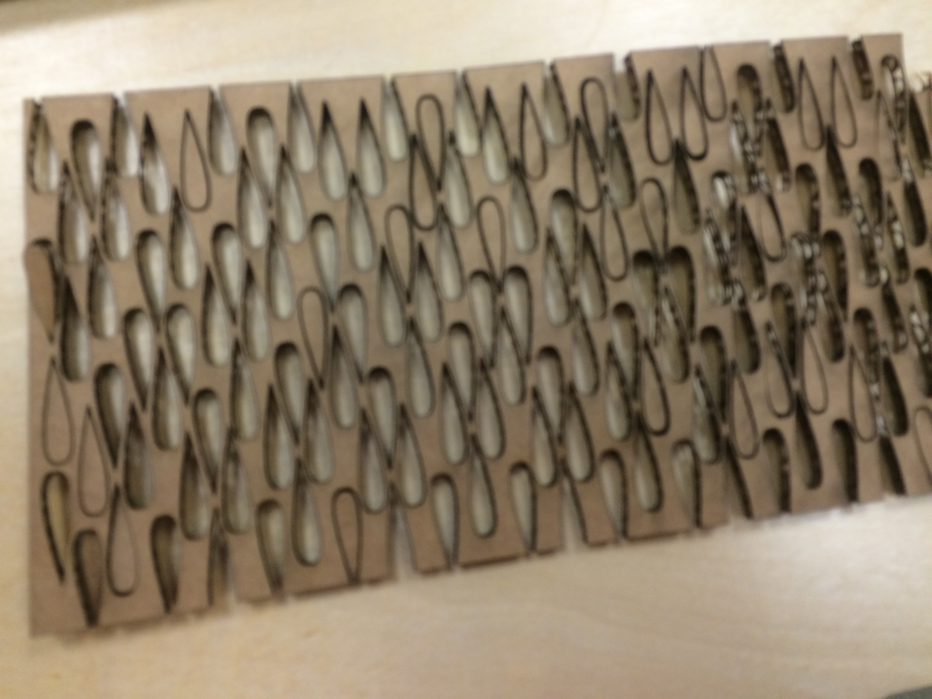
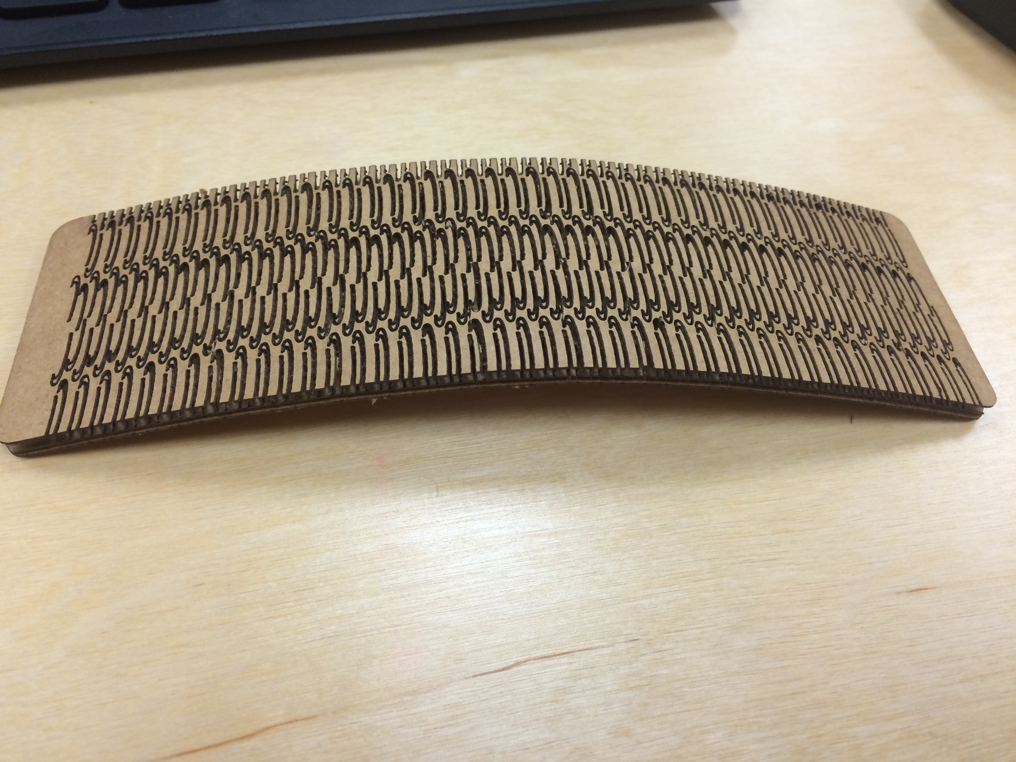
To start this week's project, I was excited to try bending the cardboard. I wanted to make flexible pieces without using straight line cuts, so I experimented with different types of cuts. First, I used little raindrop shapes (on left). Unfortunately, I ended up setting the cardboard on fire. I also didn't leave enough positive space on my design, so even the cut that didn't catch on fire didn't end up working because it was mostly negative space. So, I changed my cut shapes, and the picture on the right was a successful bending cardboard test.
I tried using the "clone" tool in Inkscape as a parametric work-around. I designed the "C" shape, which was really just a letter, and I changed its size then cloned it. A lot.
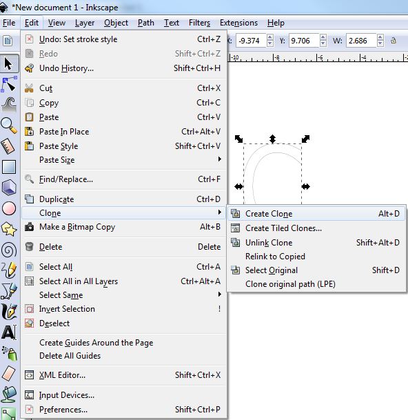
Once I cloned it, I was able to make parametric changes across all of the shapes; however, what I really wanted to do was to make parametric changes in the SPACING between the shapes. That isn't something you can accomplish in Inkscape, so I moved onto my next attemp at designing bendable cardboard.
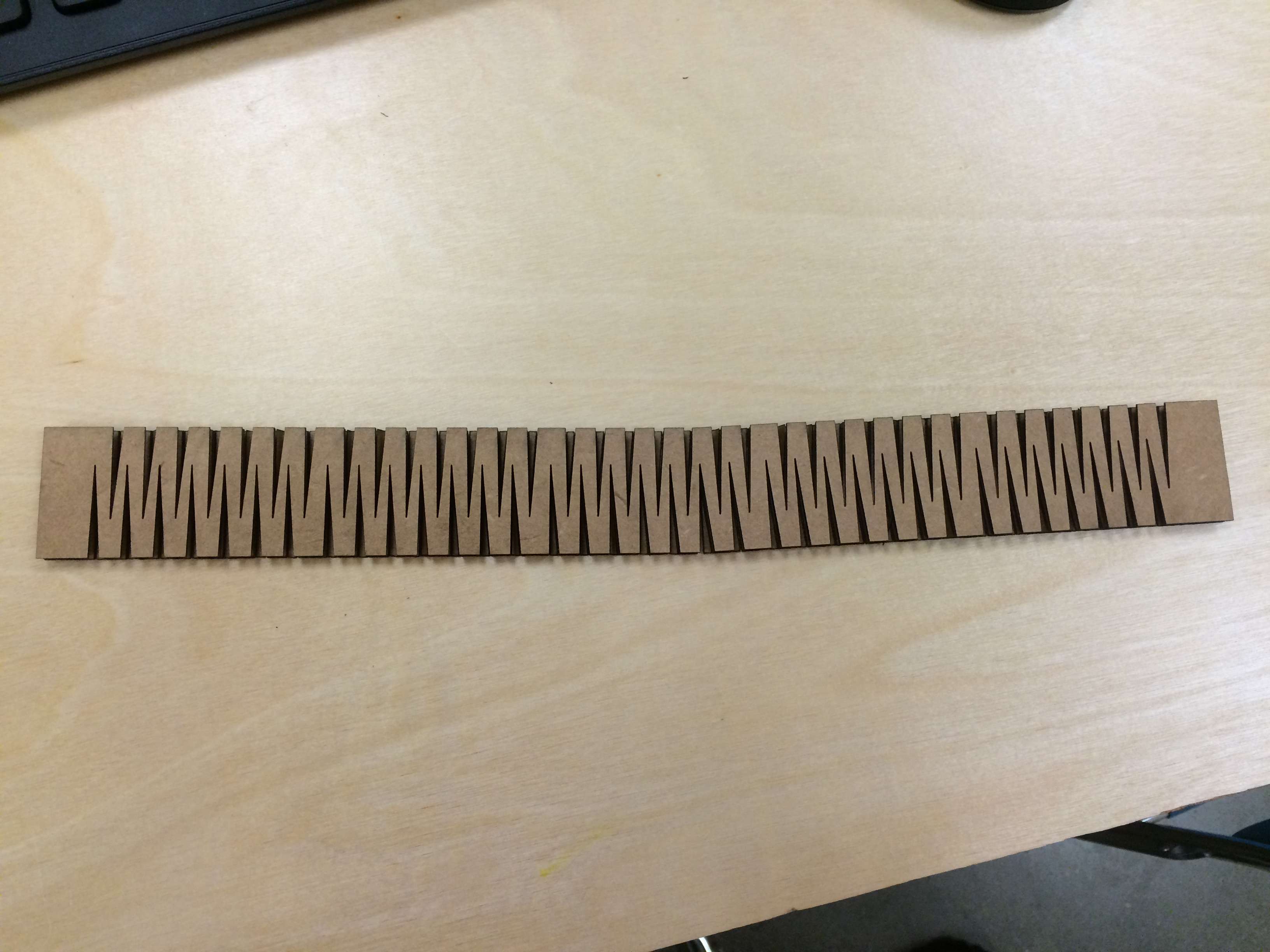
Next I tried re-designing the bending cuts in order to get a longer and thinner piece of cardboard that I wanted to be able to twist. I was able to get a piece designed and cut that was about 6" long, and it didn't catch on fire. It was a successful cut, however, the cardboard didn't twist as I had wanted it to. Because of the interior layer of the cardboard, it collapsed once it was twisted too far.
We have an epilog mini in our lab, and while doing this project, I learned a little about the settings.
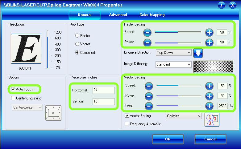
There are certain things you can change in the print dialogue window- specifically for this project were the Vector settings ("vector" cuts follow along the "hairline" width lines and are designed for cutting through the laser, an etch is called a "raster" cut). For instance, on a piece of thick cardboard, you want to cut it pretty quickly and not super hot. So, I used the setting: speed:80 and power:50. But I found that it didn't cut all the way through on the first pass. I was worried about it catching on fire again, so I didn't want to increase the power or slow the speed down, so instead I just sent it through another time.
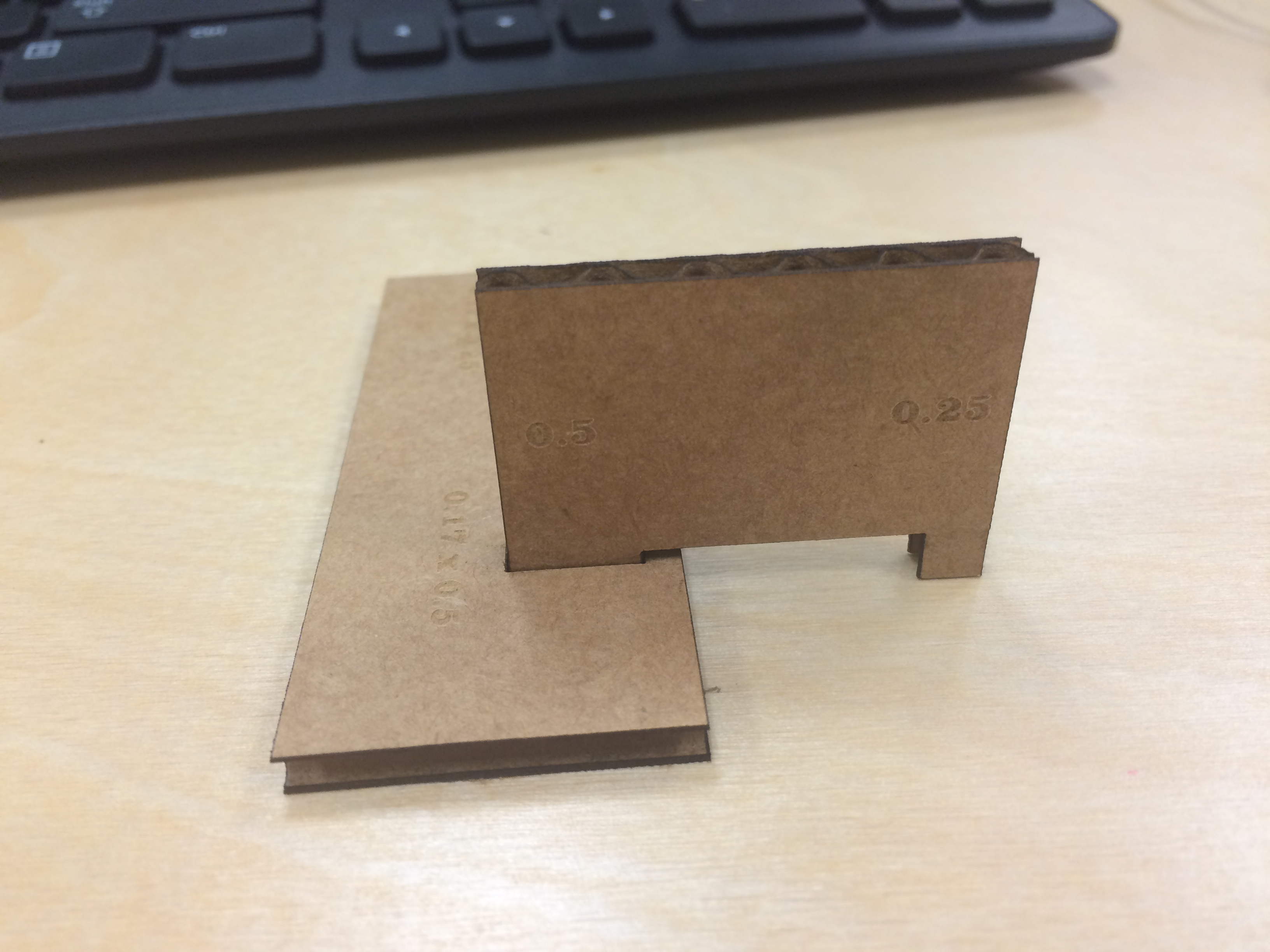
Next, in order to experiment with slots and notches, I focused on making someting a little more fun. I designed a short, long box in Inkscape. I cut a "width test" piece in order to quickly find the exact measurement I needed to press fit the box together.
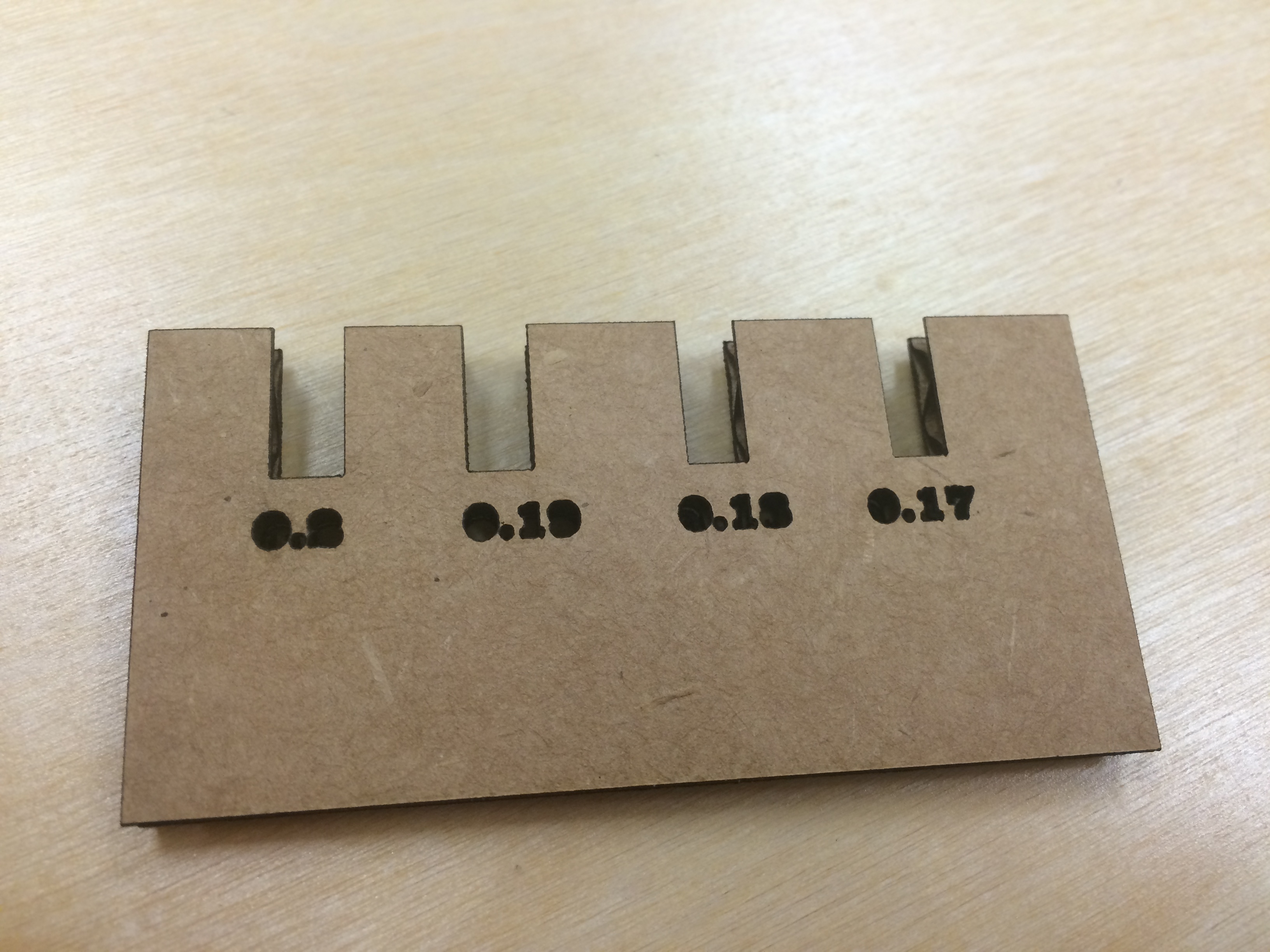
Once I had what I thought was the perfect fit, I cut the box, which ended up having just a little wiggle room in the notches. Without being able to make parametric adjustments, finding the right fit for the corners of the box took a couple of tries. I ended up using the node editor and the arrow keys, and worked out a system that didn't take too much time. My second cut worked fine.
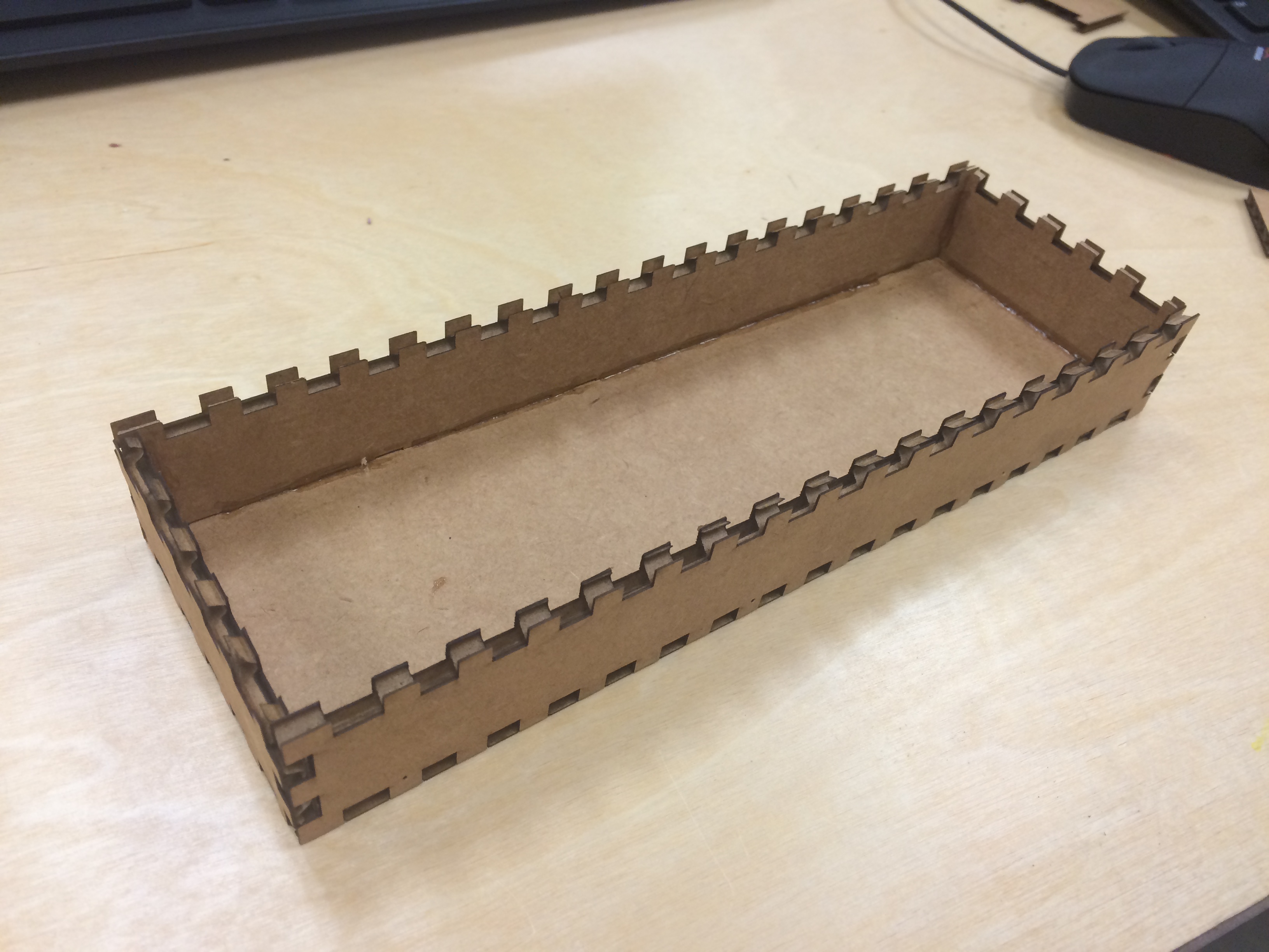
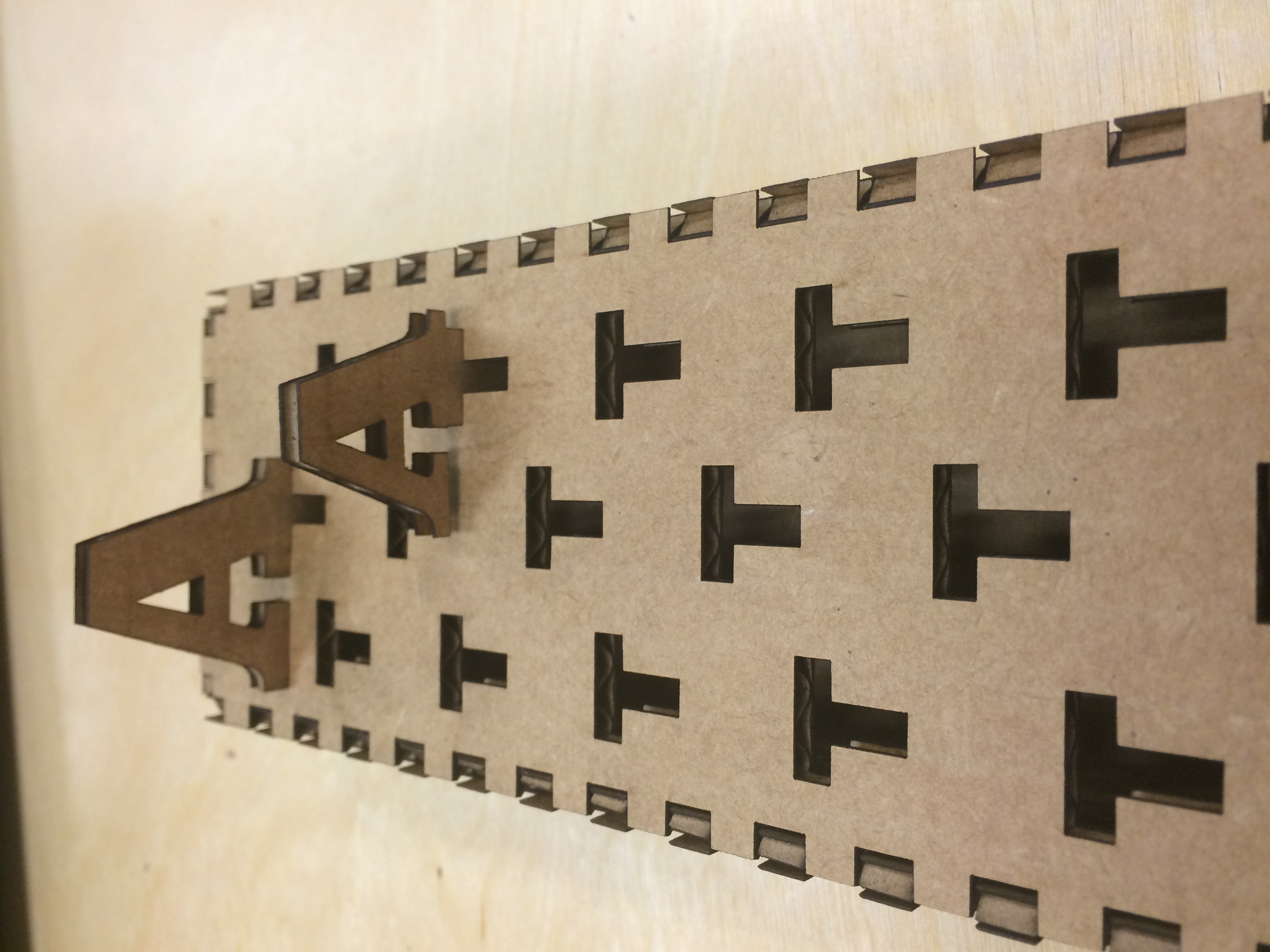
Once I had my box working, I focused on the slots and notches for my pieces that fit into the top of the box. I cut a test piece and then cut all of my notch pieces.
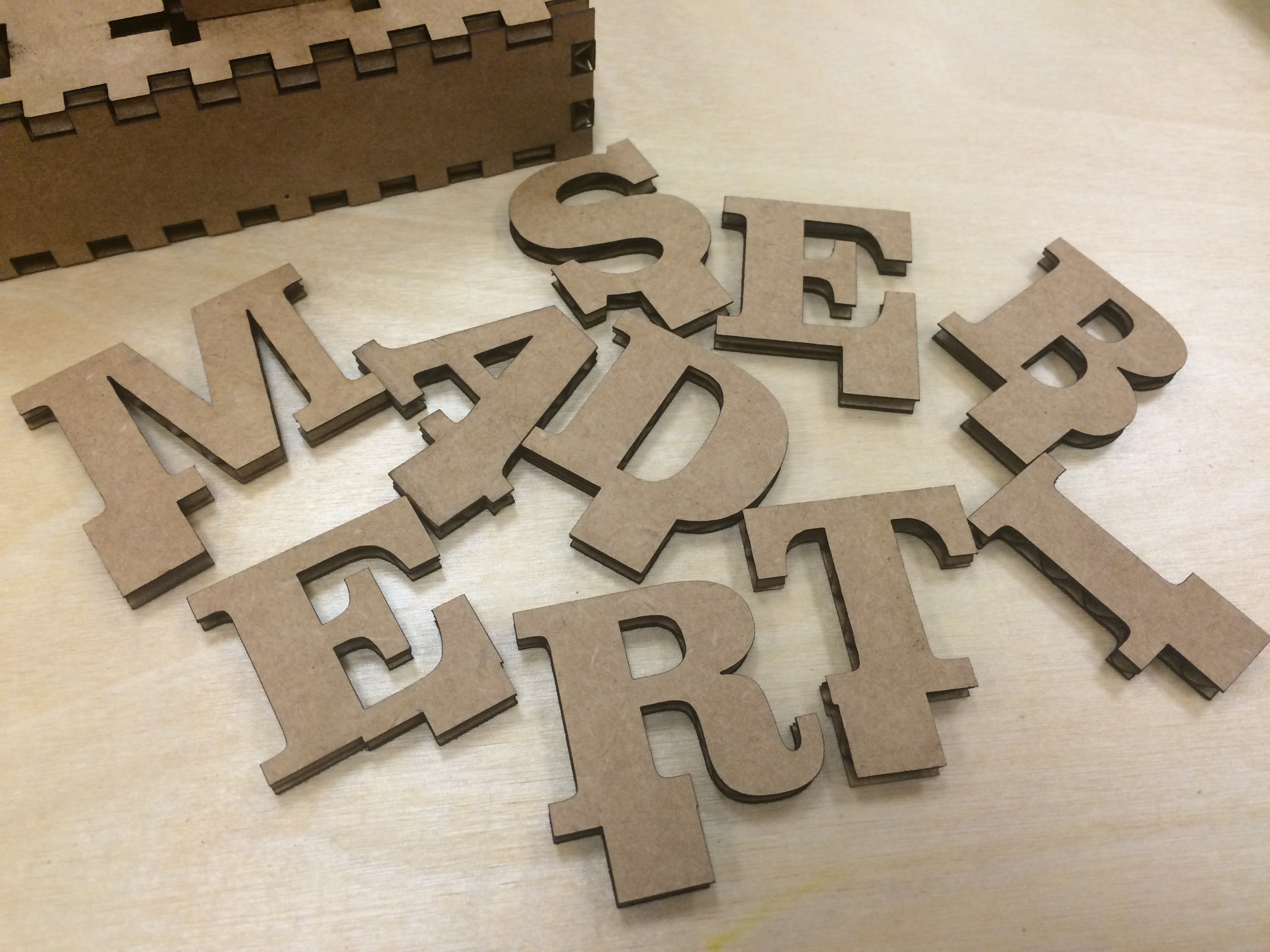
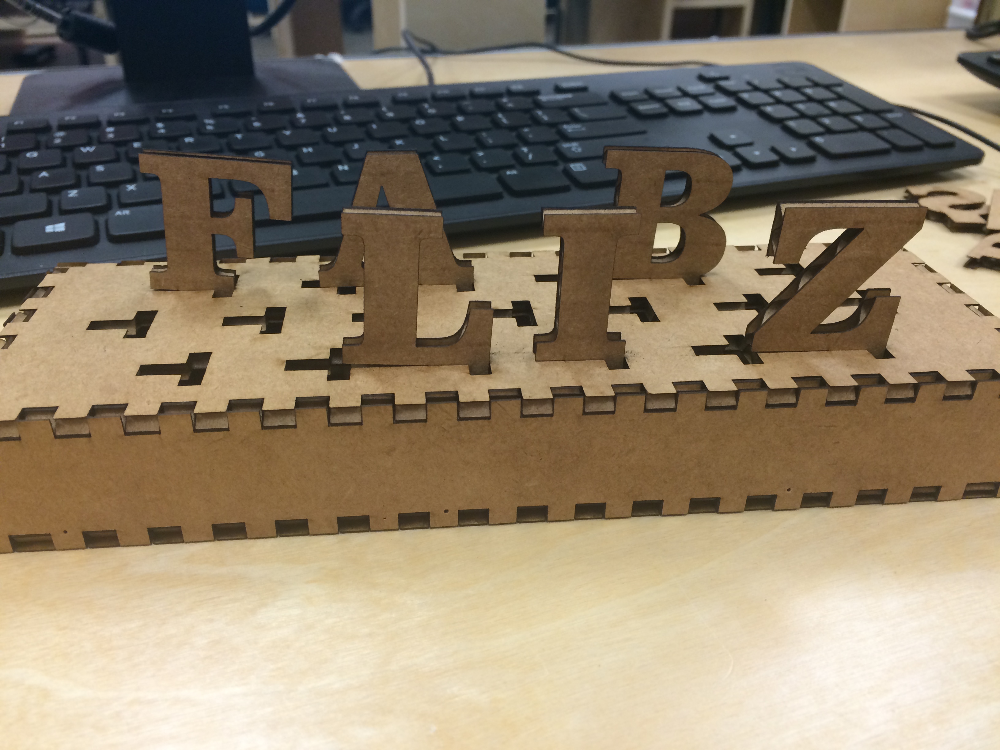
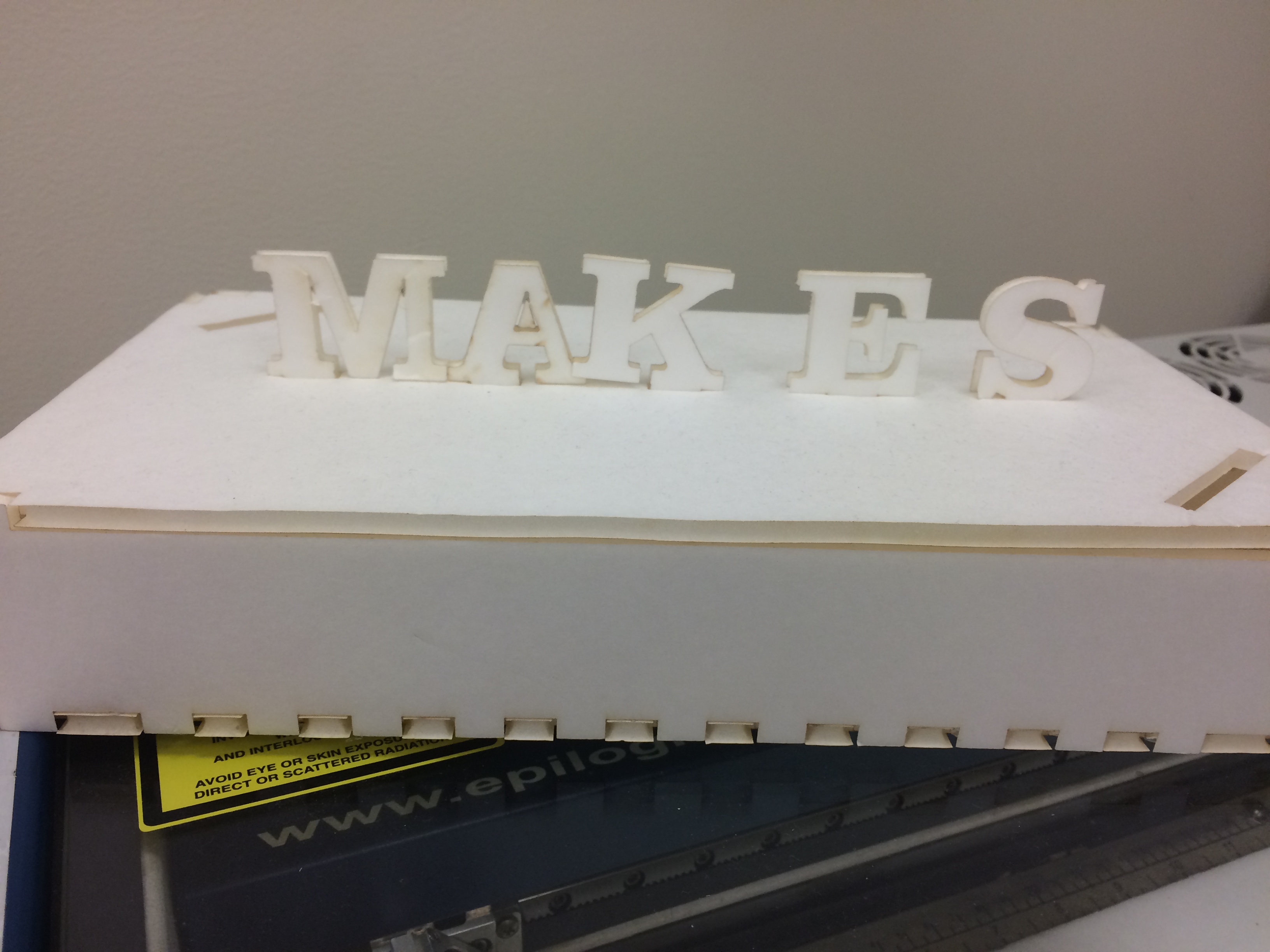
Finishing the top of the box was easy, and I was able to fit all of the letters nicely onto the top of the box. It worked pretty well, that is to say that the slots and notches were well fit. However, if I were to iterate on the project, I would re-space my notches on the top of the box so that the letters had more space in between them. Also, perhaps arrange the notches so that they are not so much in a straight line. Over all, however, I was happy with my project.
Here is my letter file, and this is my letter box file.
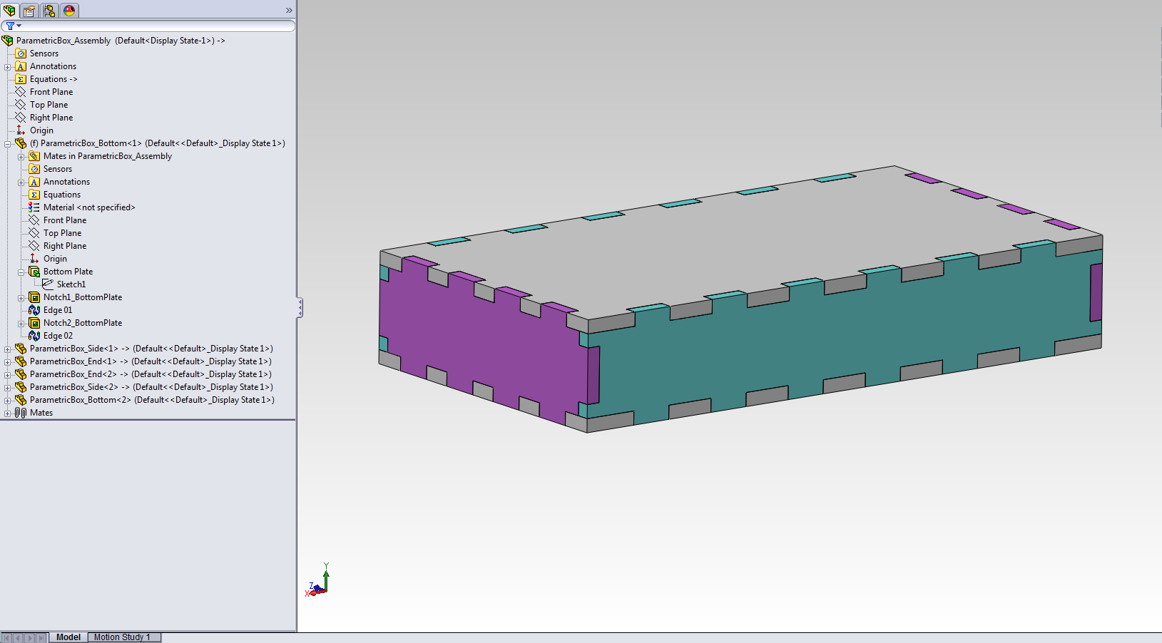
Once I had the box I wanted, I decided to try using Solidworks to design it with some more parameters. I wanted to be able to change the width of the material without having to go in and manually adjust all of the tab heights. This took quite a bit of time on Solidworks, but changing the thickness of the material will be much quicker.
I associated the notch heights and the thickness of the remaining five sides of the box with the thickness of the bottom of the box. Here the bottom is 0.25 inches thick.
In order to change the thickness of the bottom side, I had to change the extrusion width.
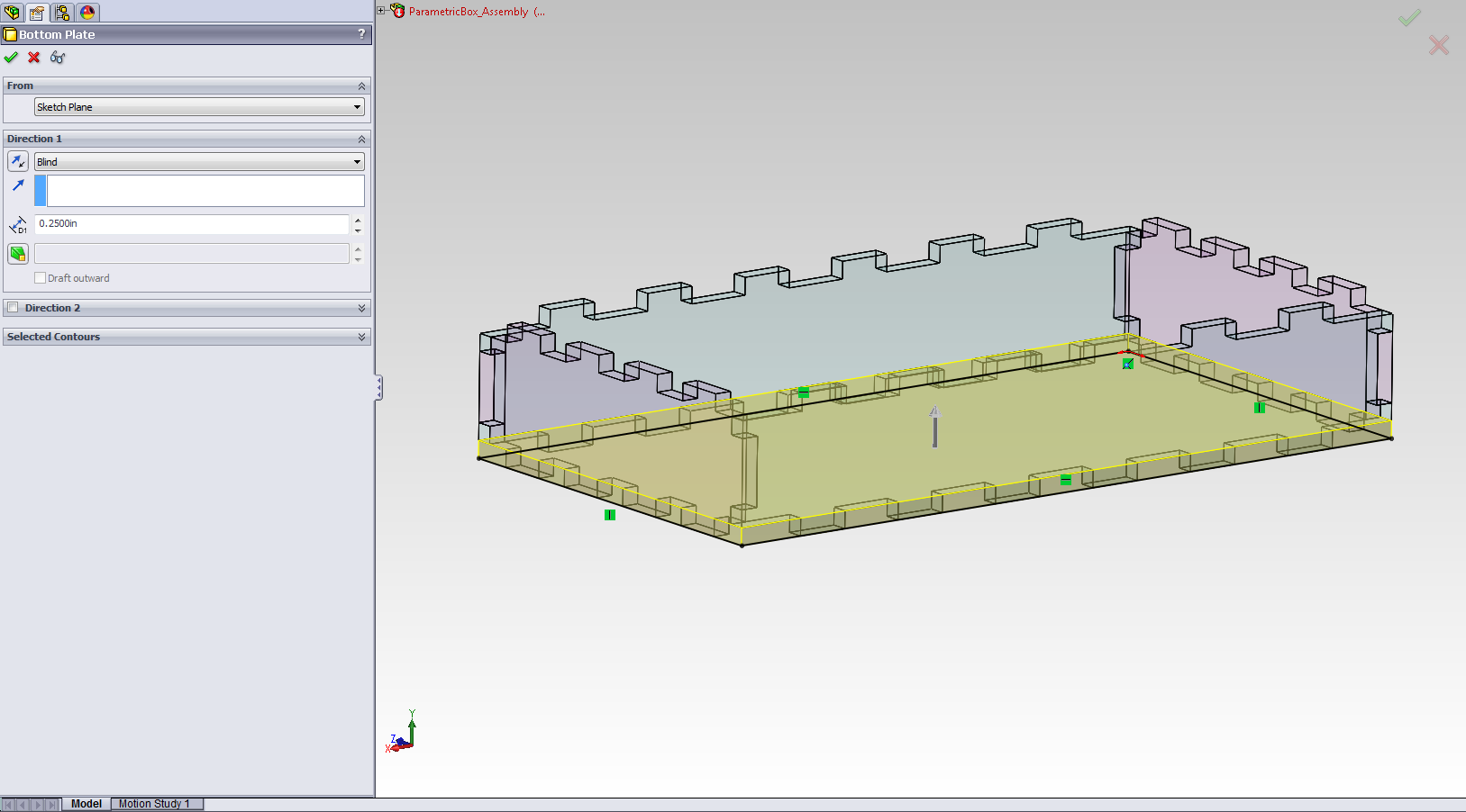
To change the extrusion width, I just typed in the measurement in the extrusion feature field. Here I changed it to 0.125.

After changing the extrusion width, I did a quick rebuild and the modifications are reflected in the remaining box sides and all the notches. From here, I just exported the faces as a .dxf drawing and cut them out of foam core.

I added my top notches after the fact in CorelDraw, and I cut out some more letters of matching foam core for a new and improved letterbox.
My Solidworks files are here:
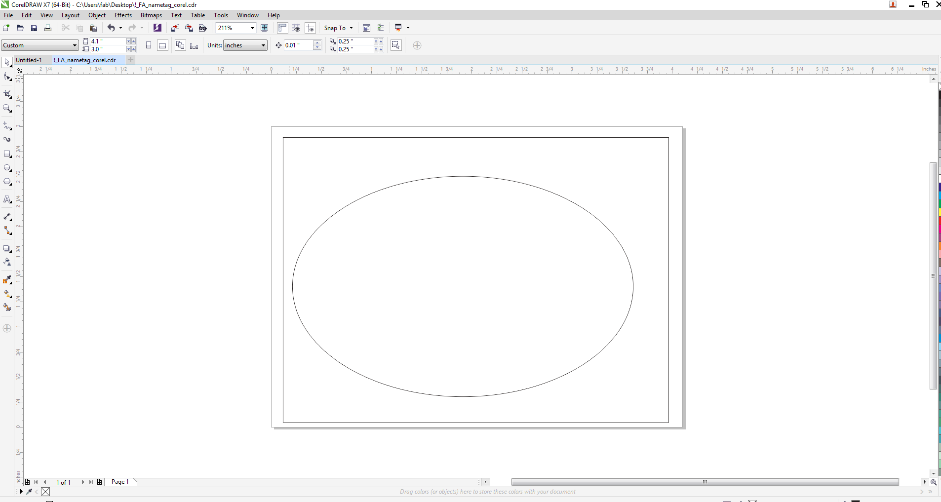
I decided to make a nametag. I designed the nametag using Coreldraw. Here is my .cdr file.
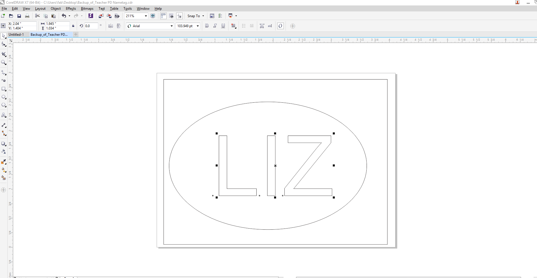
I set all of the lines to the "hairline" width for the stroke. Then, I sent it to the vinyl cutter. I made sure that the size of my page in Coreldraw was the same size I used in the printer dialogue box for the Roland.
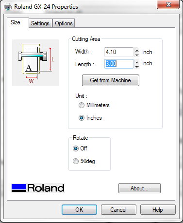
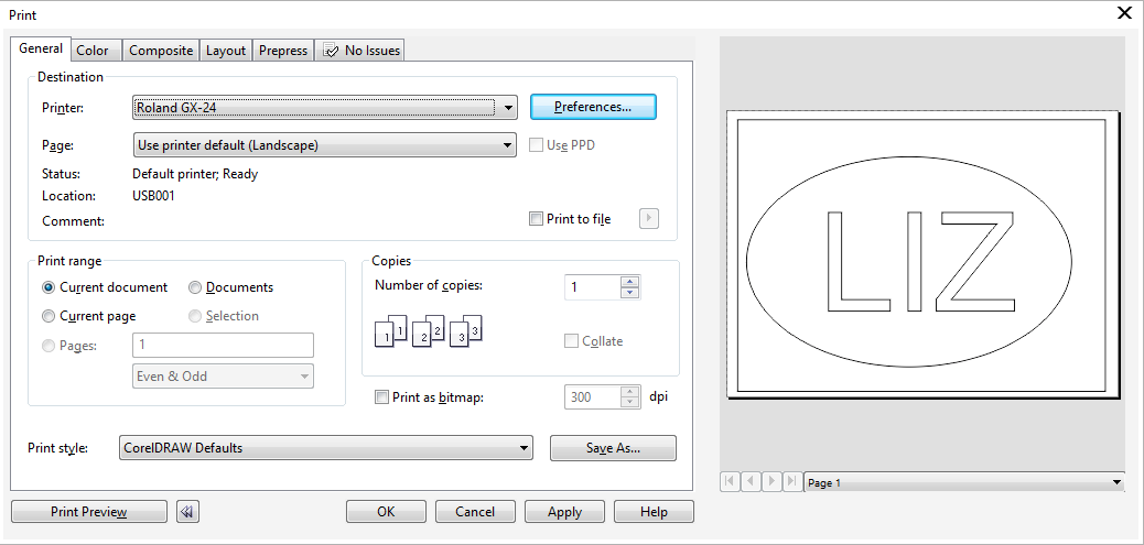
When the print review pane looked good, then I hit OK, which sends it immediately to the vinyl cutter.
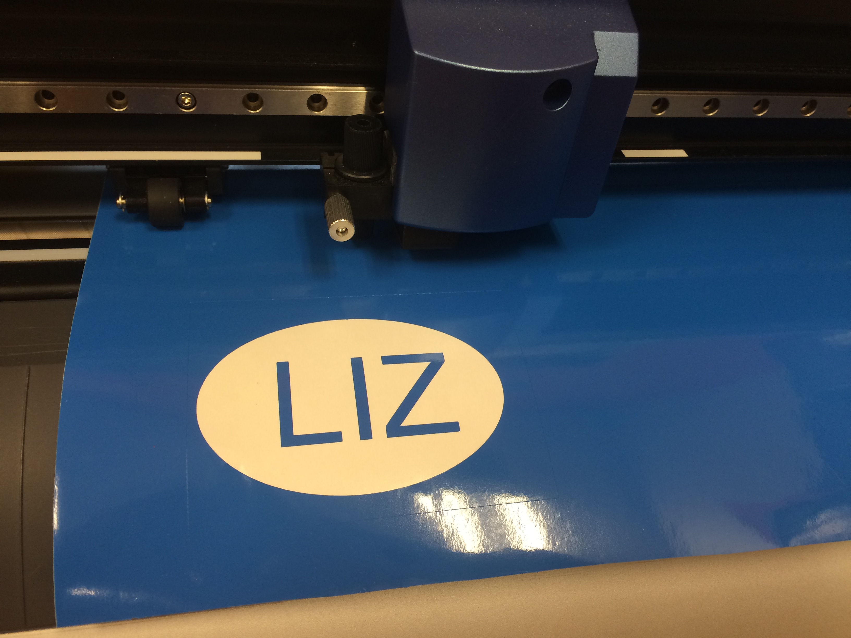
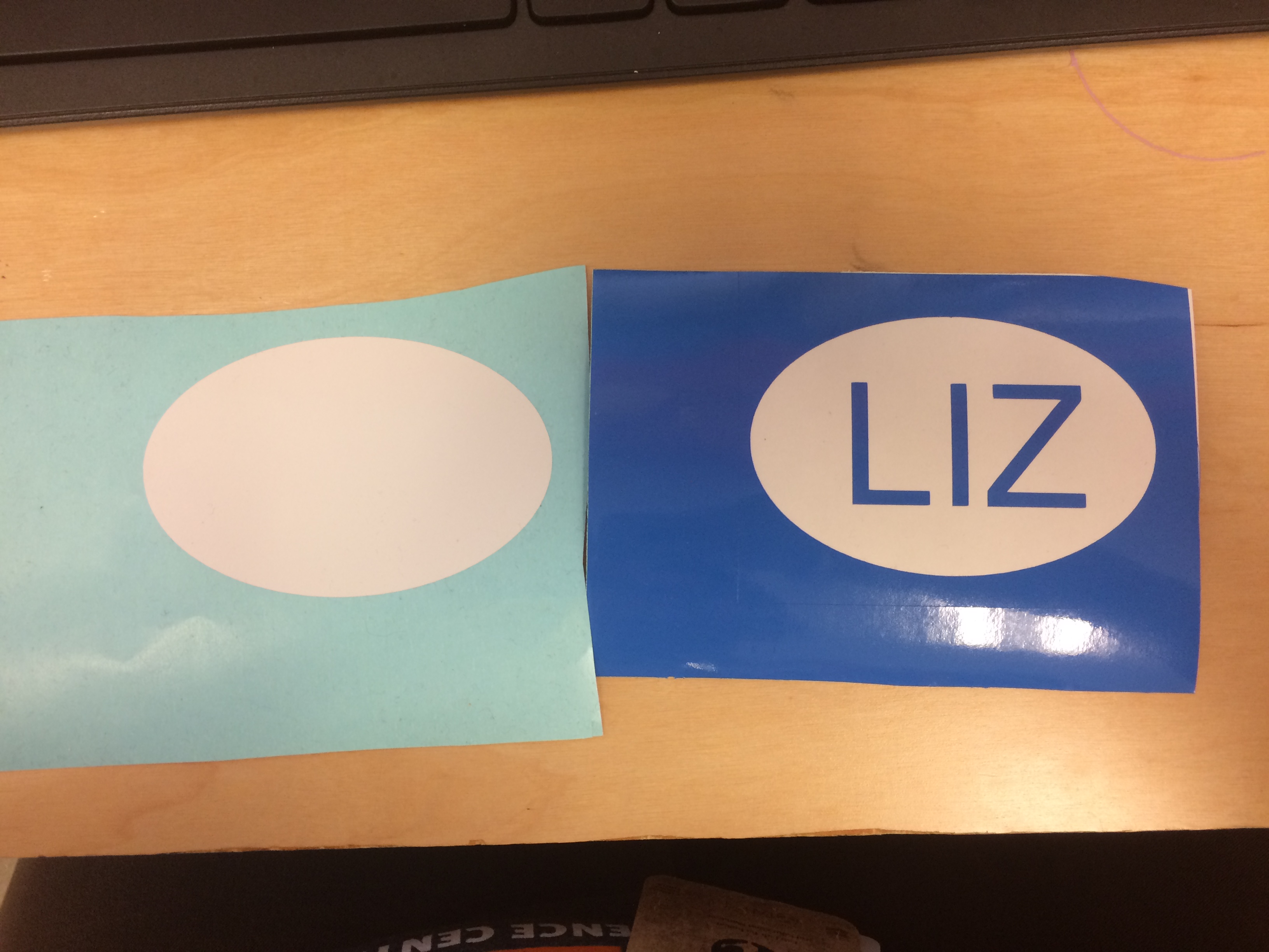
Once I had the blue cut out, I wanted to cut out the oval to place my name on. I chose white for the oval. On the Coreldraw file, I just deleted my name and sent the oval to the vinyl cutter, after changing vinyl rolls.
I cut out the oval and then I was ready to transfer.
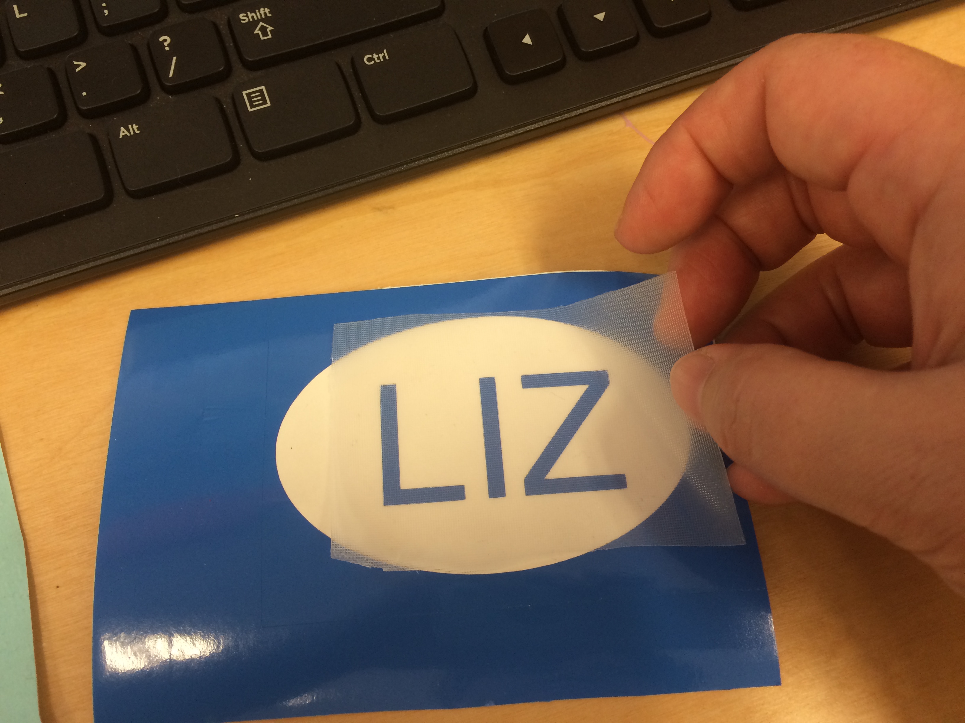
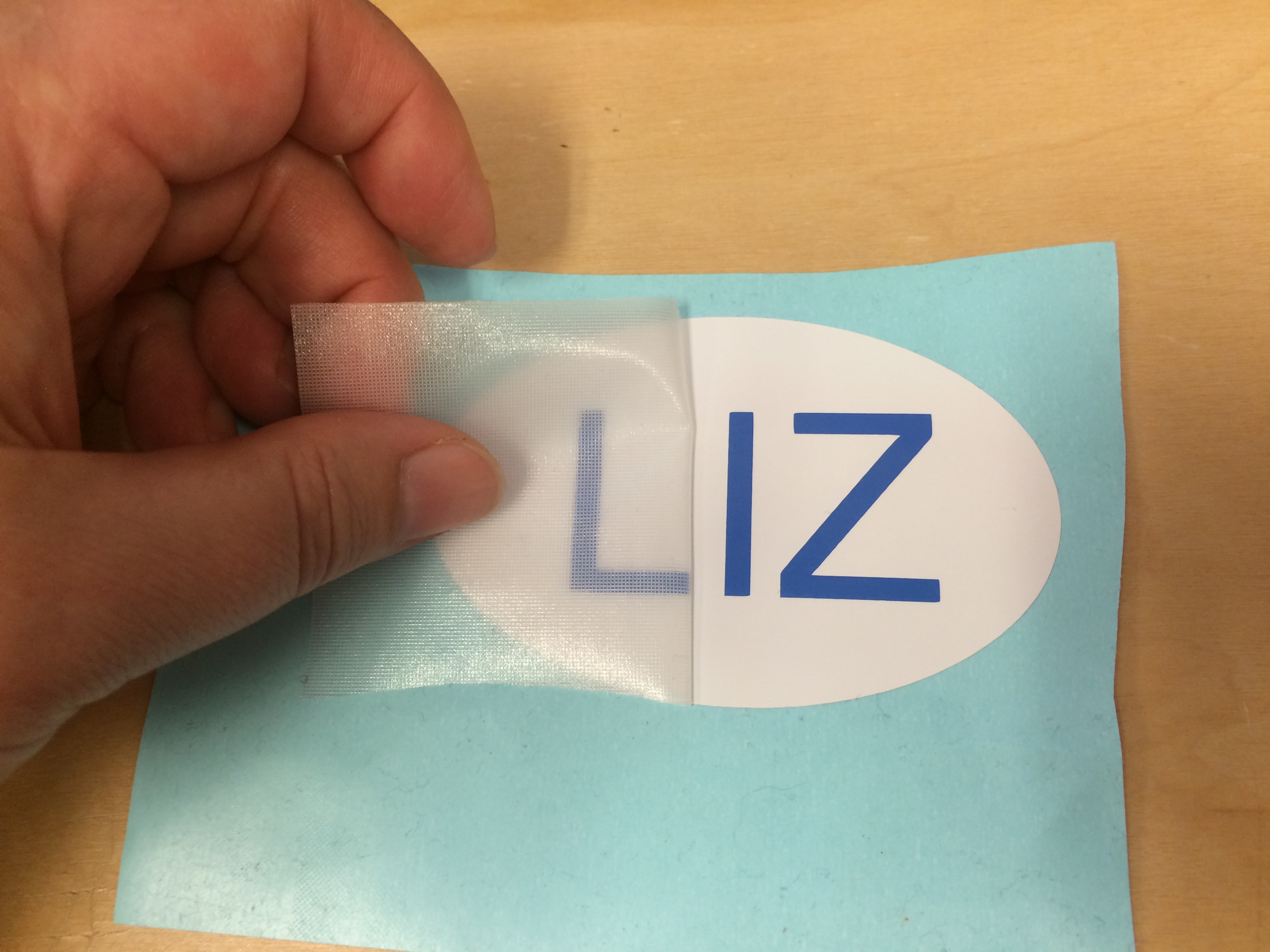
I used a piece of transfer tape to remove my name from the blue backing and then I set it carefully onto the shite oval and slowly peeled back the transfer tape, which left the vinyl letters stuck to the oval.
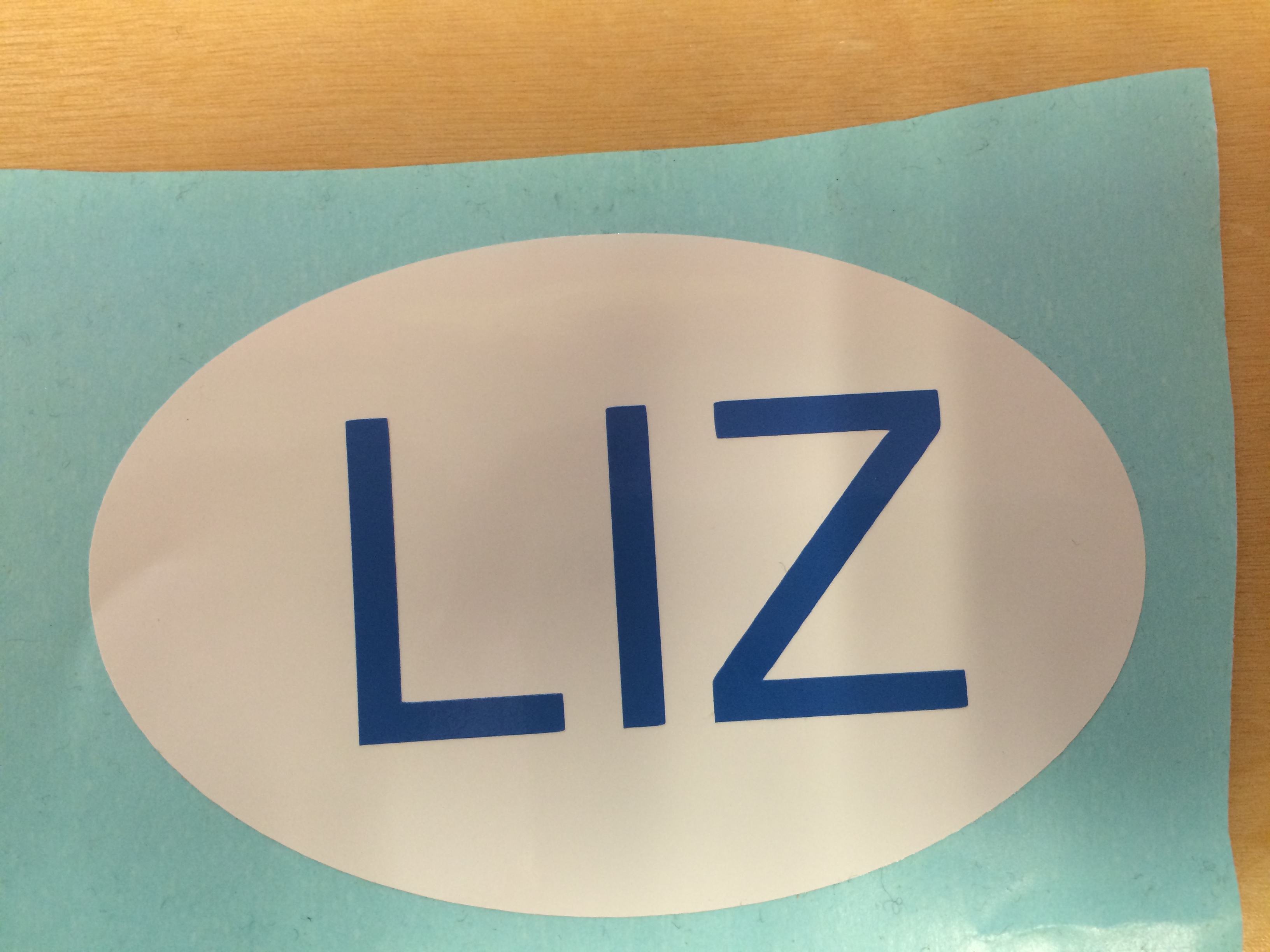
Now I have a nametag!