FINAL PROJECT / WEEK 1 / COMPUTER AIDED DESIGN / COMPUTER-CONTROLLED-CUTTING / ELECTRONICS PRODUCTION / 3D SCANNING & PRINTING / ELECTRONICS DESIGN / COMPUTER-CONTROLLED MACHINING / EMBEDDED PROGRAMMING / MECHANICAL DESIGN / MACHINE DESIGN / INPUT DEVICES / 3D MOLDING AND CASTING / OUTPUT DEVICES / COMPOSITES / EMBEDDED NETWORKING & COMMUNICATIONS / INTERFACE AND APPLICATION PROGRAMMING / APPLICATIONS AND IMPLICATIONS / INVENTION, INTELLECTUAL PROPERTY, AND BUSINESS MODELS / PROJECT DEVELOPMENT
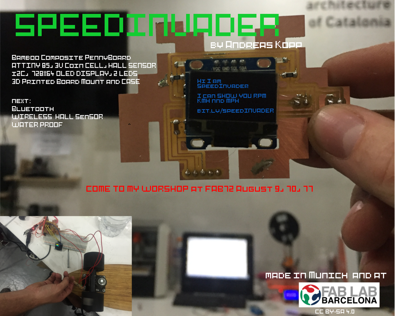
Final Project Summary - the Speedinvader
The Speedinvader - Files, Future Plans
Process - How did I make it?
Update 5 June 2016
After realizing that I will not have the time to complete all the components of a Post-it Sticking Machine I decided to build a Skateboard Speedometer instead. I love the idea that it is quite small and I can take it anywhere with me. I also already made a skateboard in composites.
Check out week17 for more details about my Speedometer. I will update while I go along.
Arduino Prototype
Update 8. June
With the help of a friend I got my Arduino Prototype to calculate the RPM (rounds per minute working) the first day I arrived back Barcelona. (This time we drove with a Mercedes Bus from Munich to Barcelona. This way I can take my Something Big with me back to Munich).
I just used a simple code I found on the homepage.
For prototyping I used a light blue bean and added a button. This is a great little arduino compatible open source board that is powered by a 3V Coin Cell, has a M328 chip, I2C, SPI and a little prototyping area.

That is the Architecture of the Light Blue Bean. It would be great if I can rebuild parts of the that.

Attiny Test
Then I tested the code with my Hall Sensor Board from Input Devices. I got it to work but I realized I needed to get the hall sensor closer to my wheel magnet.
Speedinvader First Board with Coin Cell and Hall Sensor on the Side
So I quickly adapted the hall sensor board and put the hall sensor on the side of the board and added a coin cell battery. To get everything working it took me the whole day. In the end the problem was I had not burned the bootloader.
In the code I added that my LED are Blinking according to the RPMS.

Speedinvader Second Board with OLED
Update 10. June
As I did not have a proper Attiny Holder (I know ordered one from ebay) and I now find it easier to prototype the board in eagle and mill it right away instead with a Breadboard and a million jumper cables.
For the OlED Screen I used a screen I bought earlier. It is a 0.96 Inch 128 x 64 OLED that supports I2C meaning I need to add I2C to my board design. For that I looked at Neils I2C Bridge design and added a 10K Pull-up to SDA and SCL. In Neils board there is only one pull-up but if I do not need the second pull-up I can easily replace it with a Zero Ohm.

I also added a Coin Cell Battery Holder and two Screw Terminals I found in the adafruit eagle library. The display needs 3.3 to 5V but I hope it works. As my goal is to later implement bluetooth and I do not want to add a lipo charging cycle I hope I can power everything with a 3.3V coin cell.
The process of designing, milling and soldering took me a whole day. In the end I had a copper line below my ship broke so I had to fix it with a little wire with took me almost 2 hours. Milling still takes 23 Minutes I try to get that down by making the the lines bigger and closer together.


Update 11. June
It took me like 4 hours again to solder my Speedinvader and I needed 4 jumpers to debug it. Now I know I only should use small jumpers and not big cables and be very careful to not rip of the lines when trying to cut of the jumpers.
After bootloading I tested the invader first with a Arduino blink code and then managed to find a code in c for the display and got it running. Still I did not got it to run with Arduino because some libraries were to recognized. They are special libraries for the Attiny from
sudo makeavrdude -c avrisp2 -p t85 -U flash:w:"main.hex":a

I am not sure if the coin cell works yet. So I made a new design and added a 5V voltage regulator 5V to it to get get the Volts of 2 3V Batteries from 6V to 5V.
Update 12. June
This link from instructables was a great help in getting the Arduino code working. The two sketches and the libraries worked right away.
I thought about an interface to show a big number in the middle of the screen but could not find a working library for a big font so I first decided to show RPM, km/h, mph and max speed in kmh.
To get from RPM to km/h you just need to measure the range of the wheel in m and multiply it with the RPMS times 3,6 to get to km/h.
Also I made a test with a power supply with 3V and 200 ma and I got the screen working so I wont need to add a voltage regulator and two 3V batteries. The datasheet of the screen says 3V to 5V.
Update: I still did not got the screen working with only a coin cell.


Update 13. June
On Monday I milled the 3rd version of my board. I added a button, and another 1uF capacitor to the design. I was able to burn the bootloader and program the board but then suddenly I could not program the board anymore. I fixed a small break but did not find another error and could not program it anymore.
Update 14. June
I had to leave Barcelona for a conference and only had time in the evening to check if the error was with the FTDI Cable or the AVR ISP. First I got the same error with another board but was then able to program it.
Update 16. June
I again had to work all day at a conference and was so exhausted in the evening that I took the time to catch up on week 19 lecture videos and final presentation presentations.
Update 17. June
I am back in Barcelona! I took a very early morning flight. Today I want to get my final invader working and design a housing. So I checked all the connections and all worked. Ferdi helped me and at least I can now program the chip. But now the LEDs only get power when connecting the ISP Cable. Still there must be some bad solder joint.
Update 18. June
Today I tried again to get my newer versions working but was not successful. But I got my first board version working and uploaded some new code. I also played around with the code and finally understood how to convert bitmaps into hex and show it on the screen. At the end of the the day I wanted to connect a voltage booster and clipped of the battery holder in the back but this was a bad idea, because the board stopped working again.
Also sometimes I cant program the board when I know that all connections are working. I read that it may be a problem with my USB port.

Update 19. June
Today is the last day to work on the final project before the presentation. I know I should have done demand side time management but the So I will focus on the housing today the slide and the video.
I managed to finish the case for the speedinvader and got the last invader working. Here are my design files on tinkercad. I made the mistake when mirroring the component to not check that the pins are in the correct order.

Now I got quite comfortable with the Attiny45/85 (with 256 and 512 bytes, 8 pins) but it would have been easier if I would have used the ATmega328P (2KB, 27 pins) because I could used the same functions and libraries as the Arduino Uno and not look for special Attiny libraries.
Still I think the Attiny85 is the best choice for my kind of project This website and this guide on Sparfkun got my into it more. Here I read about I2C on the Attiny85. There they mention to use at least 4,7K pullups. But I have to find out how you can do them internally and not need to use them. The project of Ilya did not use pull-up also he got the screen working with 3Volts.
I am realizing that for prototyping it was not smart to do all boards in invader shape. Next time I will make the boards as small as possible to fit as many boards as possible on the mill.
Also I will buy a Tiny AVR programmer for future work with the Attiny.

This PDF from Sparkfun is great if you want to get into programming with the Attiny.
Update 20. June
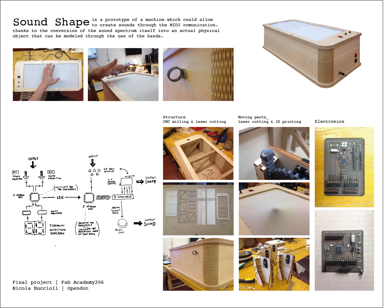
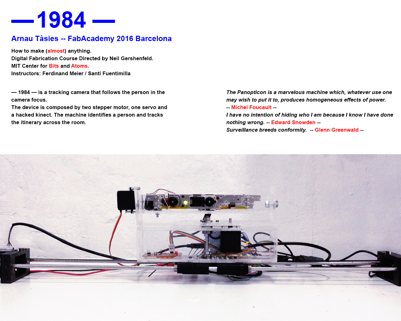
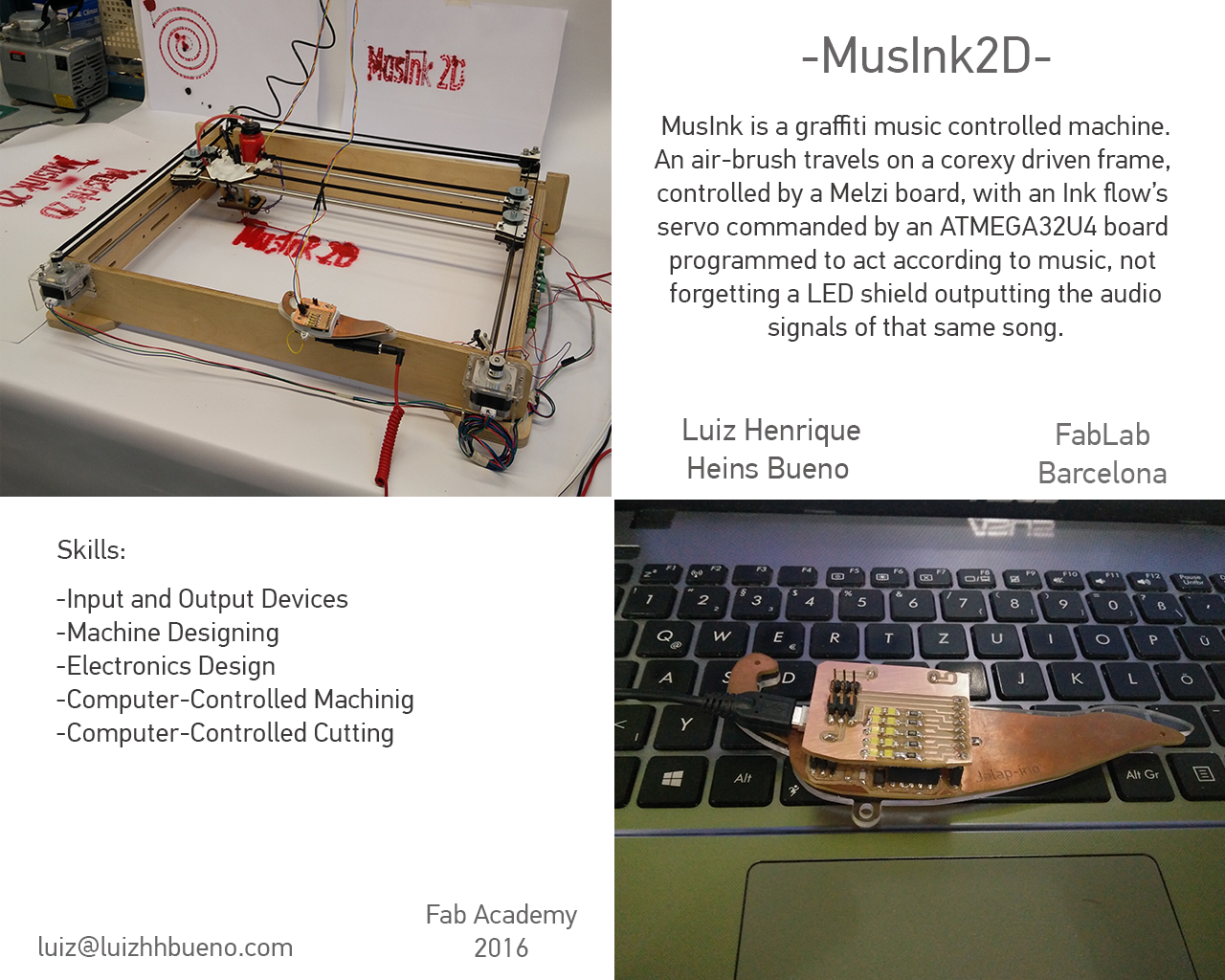
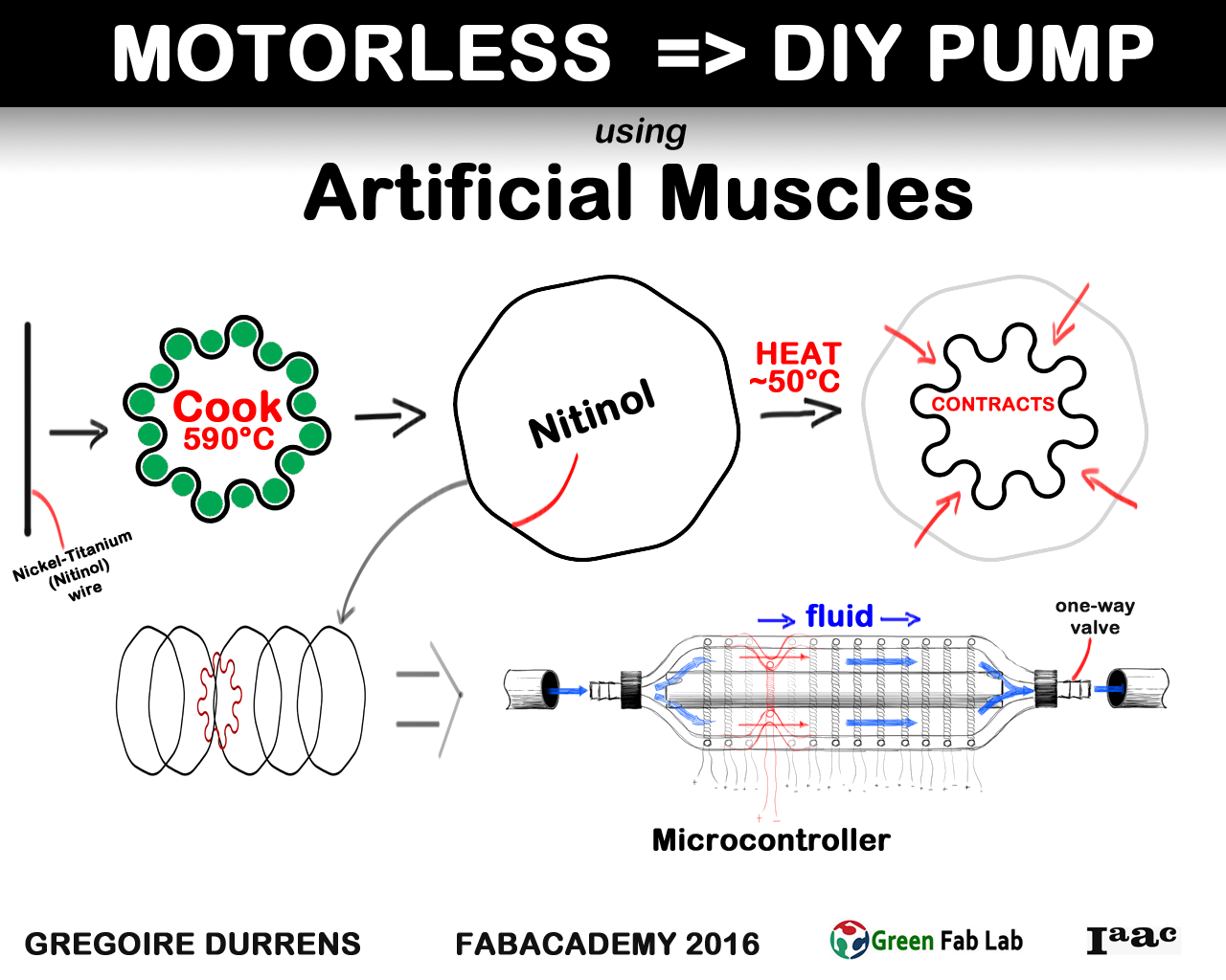
While documenting I watched the final project presentations from the 17th. I really like the the LED Board from Torino, soundshape and obviously the projects from Barcelona.Arnau with his 1984, Luiz with his drawing robot, Guillaume with Aquaponics and Gregoire with his pump. I would also like to integrate a motor like Kosuke Kaneko did with his Motorized Skateboard and add some lights into my board.
Here you can find my firmware for the speedinvader so far.
Update 21. June
I printed a housing all night only to realize the next day that my board is too big to fit my housing. Also I realized that I have to design a housing for my breakout board as well.
Also I finished a slide during the night and did a live video of my project and presented it later to Neil.
Update 7. July
Converting bitmaps to C Arrays
I was working late and got into the converting images into C arrays so I can display images on the screen. There are a couple of Image Converter like this and this but I did not quite understand how to use them.
There are also software for the Mac you can download. Like this. Also I went through the adafruit tutorial..
And there is also bitmap to c converter for windows here.#
Finally I found the right software for me. Its a nice bitmap to C converter). To make a bitmap of you image you can use gimp.
Also got interested in playing music. I think it should be possible to add a little buzzer to my Attiny and play a space invader sound.
What is still missing?
Design and mill Hall Breakout v1Program Board v1Code for OLED Display in ArduinoAdd Condesator and Button v3Mill and solder board v3Design and mill Hall Breakout Double SidedDesign Housing3D Print Housingmake slidemake video- Design Mold for Housing
- Mold Housing
- make a smaller board version
send board to be made in China
optional: Raspberry Pi Zero HAT
- optional: add Bluetooth and Radio
- optional: Make a Light blue bean hat
Project Files
Download all project files of my Google Drive or from github.
Feedback ?
Twitter me or email me at andreasrkopp at gmail dot com.
Or chat with me on gitter.
