Week04 - electronics production //////
Assignment:
Make your own FabISP.
The Electronics Production assignment is to mill the board, stuff it with components and program it. We will be using these programmers through the semester to program the other boards we create.
Tutorial:
Week 4: Electronics Production
GENERAL CONCEPTS
What's a PCB?
Printed circuit board is the most common name but may also be called “printed wiring boards” or “printed wiring cards”.
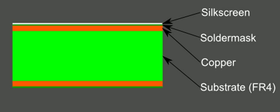
PBC Composition:
A PCB is sort of like a layer cake or lasagna- there are alternating layers of different materials which are laminated together with heat and adhesive such that the result is a single object. PCB rigid materials: FR4 (epoxy glass) / FR1 (phenolic paper). We use FR4 for this assignment.
Source PBC:
PCB Basics
MILLING
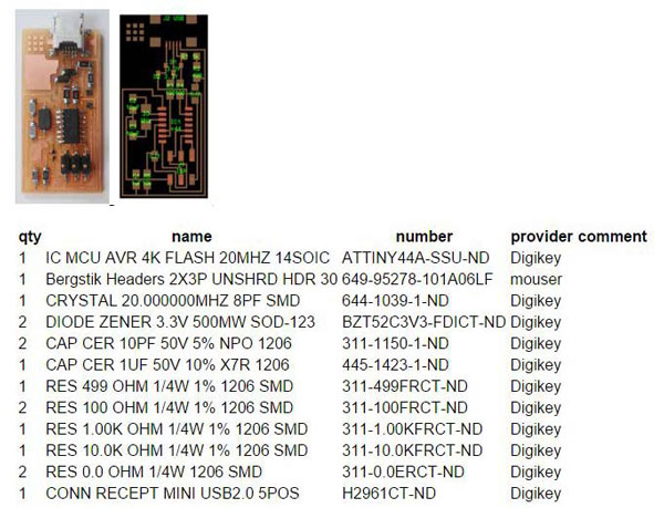
First we need to choose the board files, I chose Neil's board (don't forget to change the logo).
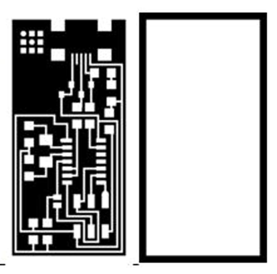
The first image are the circuit board traces (mill using the fab modules and a 1/64" bit) and the second one is the board outline (mill using the fab modules and a 1/32" bit).
Dowload files:
Circuit board traces
Board outline
USING FAB MODULES
Open fab modules from Fab Modules
Sending circuit board traces and board outline to mill:
1-Select the input format (.png)
2-The output format (in this case Roland SRM-20 mill)
3-Process for traces: PCB traces (1/64)
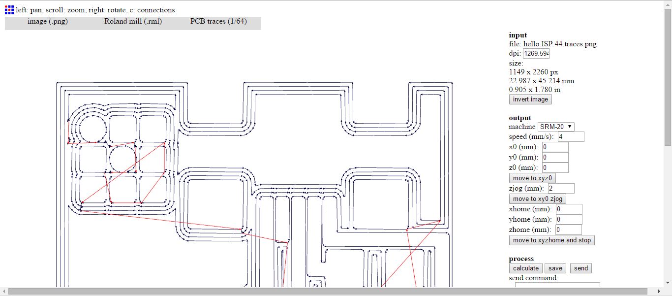
The four lines represent the number of offset.
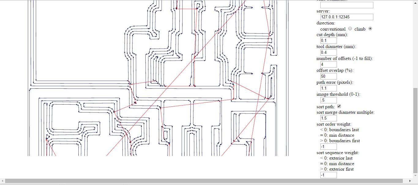
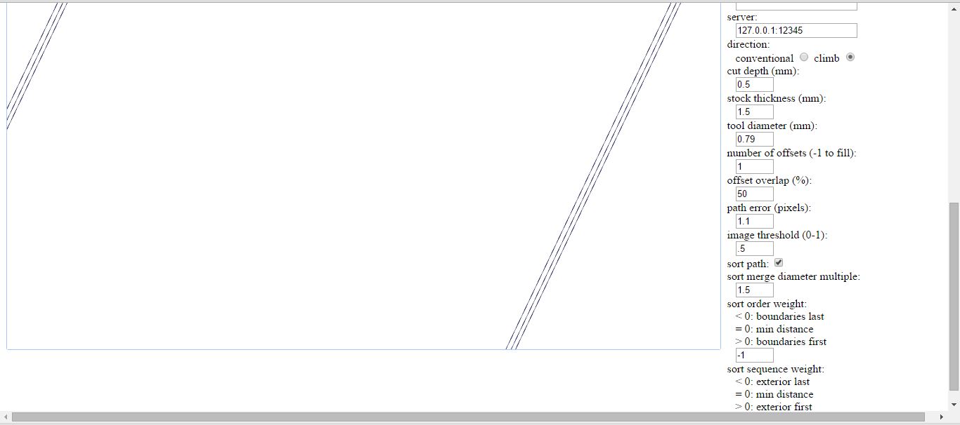
Process for outline: PCB outline (1/32)
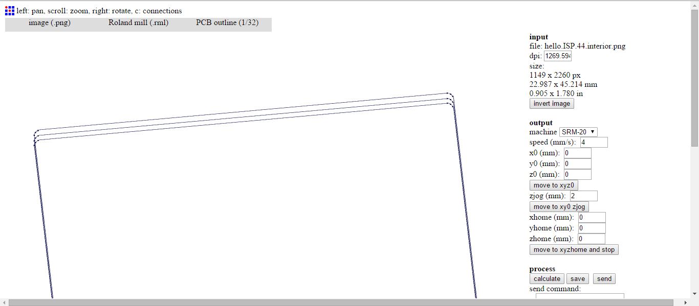
The three lines represent the cut depth / stock thickness.
4-click Calculate and then save as .rml format.
Traces Tutorial
Interior Tutorial
MACHINING - Roland SRM-20 mill:
Setting up the mill is very important to make sure that the board is straight. We have to remove the rests of the previous PCB and the tape used to fix the material to the bed, and finally clean the glue with ethyl alcohol (the plate is removable).
The surface has to be completely flat, so now we can place the new PBC with a new tape.
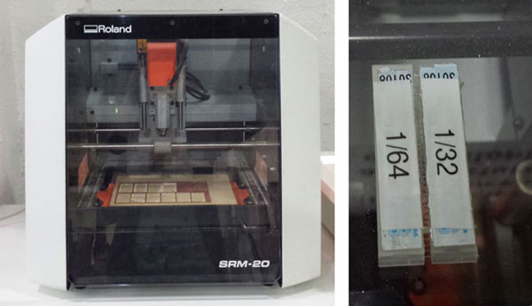
We have to put the correct drill into the machine (1/64 inch for traces, 1/32 for cutting) very carefully, it is easy to break the needle, also make sure that it is well holded (I had troubles with that).
SENDING THE FILES
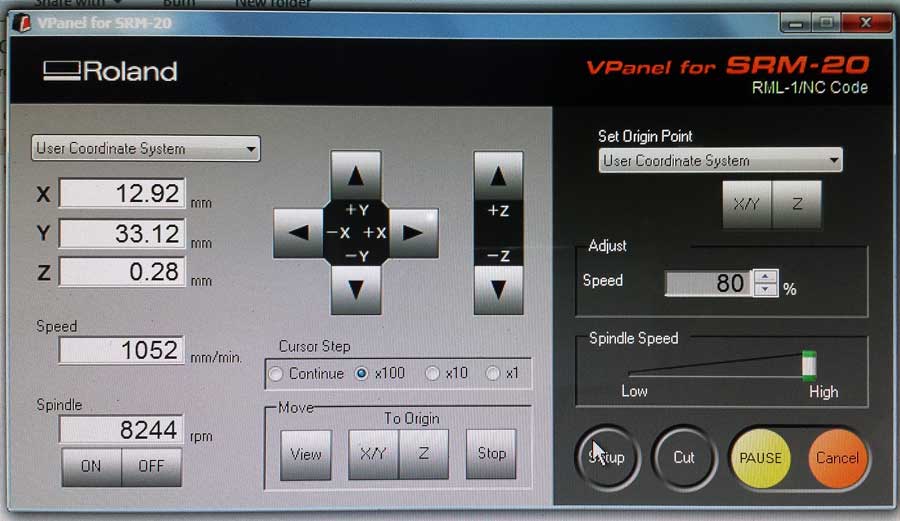
Before sending the files (from Fab Modules) to mill we set a new home point (x, y) on the software, but established the right height (the z axis) manually by lowering the drill until it just touches the board. Finally press cut, choose the file (first the traces and then the outline) and send it to mill.
We have to stay alert to stopping the machine if anything goes wrong. The fastest way to stop the machine is opening the cover.
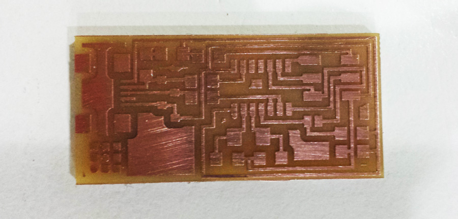
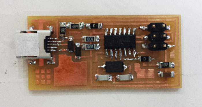
My first PCB!
SOLDERING
Ferdi and Santi gave us a brief but very useful lesson of PCB and components, they explained us the function of each component within the plate. This lesson and the tutorial on the fab academy website gave me all the necessary information and good recommendations regarding the order in which the parts should be soldered.
Fab ISP: Electronics Production Tutorial
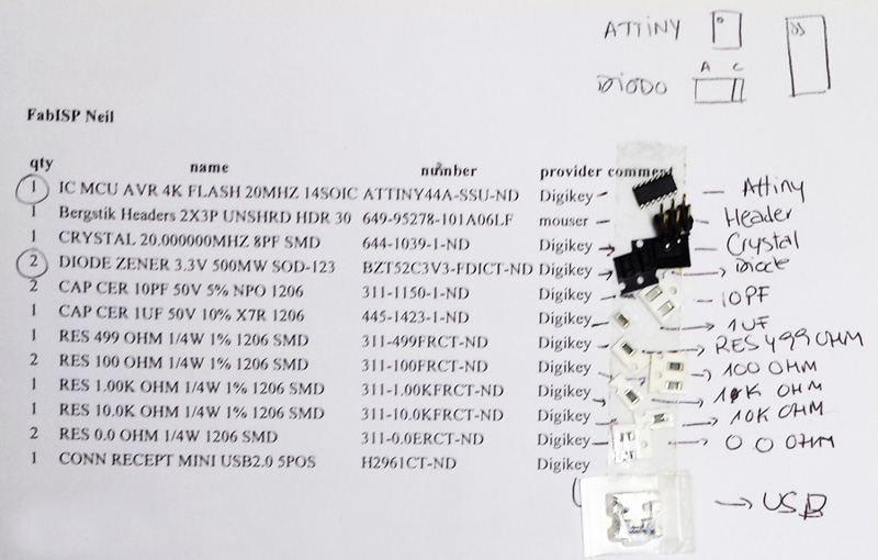
Be careful and organized while taking the components from the drawers, it's easy to make a mess. It is very useful to paste with double-sided tape each component next to their name on the list before starting soldering. I forgot to take a picture of my list, so one of my classmates lent me his picture (thank you Arnau).
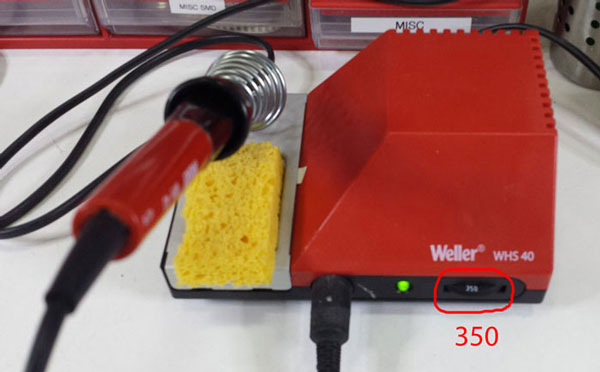
We use the WHS40 WELLER - Soldering station.
Soldering can be stressing and relaxing at the same time. I spent more or less like two hours and a half soldering the board. I almost solder all the board myself, but at the end Ferdi helped me with the smallest USB connections. I recommend starting with that component.
PROGRAMMING
Before programming we had to check in all the connections with the voltmeter following the
FabISP labeled board diagram. If you hear a "beep" it is means that it is connected, if you don't they are not connected, the ground and the voltage don't have to be connected, neither the + and the -.
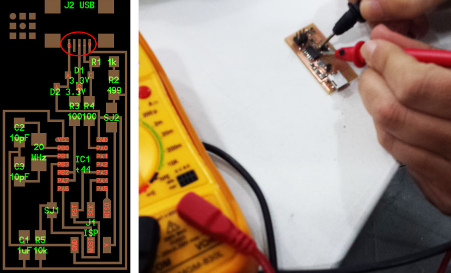
I checked my board and I didn't have connection between the PA4 and the SICK, and I had to return to solder again. After that everything was checked ok! so I got to the tutorial and followed the steps to programm my board.
I have windows in my computer, so I followed the steps for windows, but I had problems with the WinAVR, my computer doesn't read it. Finally I decided to install Ubuntu in my computer doing a partition following this links below:
Download Ubuntu
Download Pen Drive Linux's USB Installer
Install Ubuntu 14.04.4 LTS using a USB drive
Disabled secure boot
So now when I want to get to Ubuntu I have to follow this steps:
1-turn off the computer
2-press the power button to turn on the computer, then immediately press esc repeatedly, about once every second, until the Startup Menu opens.
3-Press F9 to open Boot Dvice Options and choose Ubuntu
After that I followed the Tutorial for installing the necessary software for AVR Programming, but this time for Ubuntu.
Fab ISP: Programming Tutorial
1-Ubuntu Software Install (follow the steps from the tutorial).
2-Power the FabISP Board, conect the AVR to your computer.
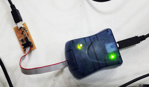
Helpful ATAVRISP2 Programmer Light Indicator Messages:
Green Light: means that the header is soldered correctly, the board is getting power.
Yellow Light: means that the board is getting power, but most likely the 6-pin programming header is not soldered correctly (re-flow your solder joints / check for cold joints, check for shorts).
Red Light: means that the board is not getting power - check for shorts.
Green light!
3-Program the FabISP - All OS (follow the steps from the tutorial)
4-Verify That Your ISP is working correctly (follow the steps from the tutorial).
Last step, desolder the jumpers: SJ1, SJ2.
Download files
home