Week03 - computer-controlled cutting //////
Assignment:
Design, make, and document a parametric press-fit construction kit.
DESIGN
How to calculate the dimensions for making joints? It depends on the machine but for the first test:
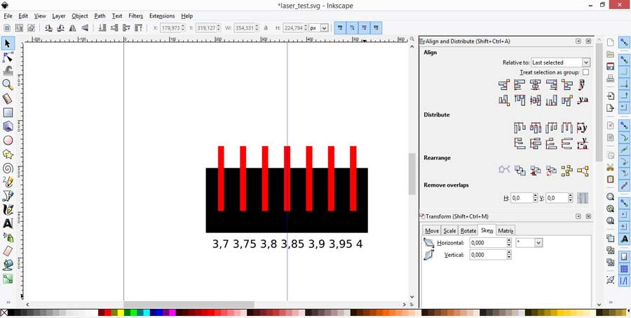
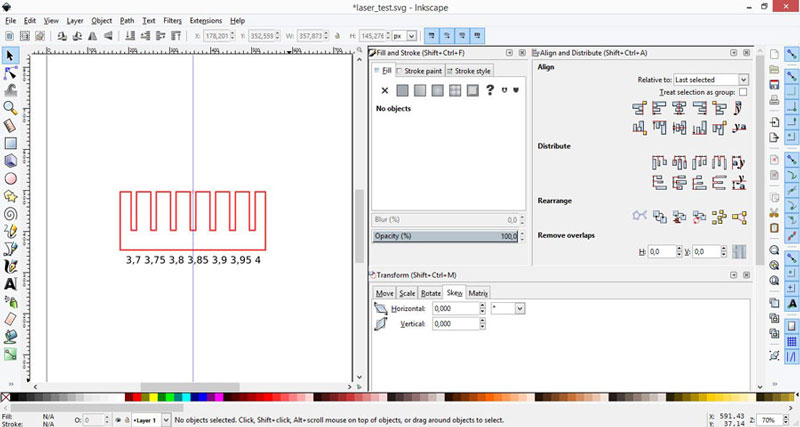
LASER TEST
Start with a simple drawing (in this case we use inkscape) without the stroke, testing different thickness, this test is for a 4mm cardboard. In my test the cardboard went from 3.6 to 4.1mm.
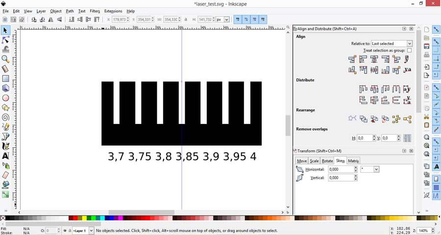
Save the file as dxf for the lasercutter:
RASTER TEST WITH TOYO ITO
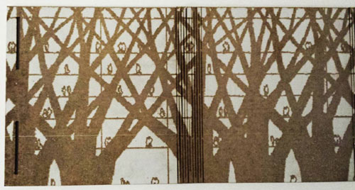
I did several raster testing with this image:
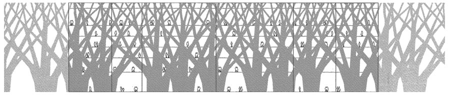
Test on cardboard, black and white image (jpg file, 72dpi):

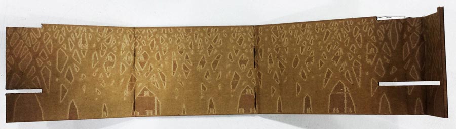
Cardboard (3mm), Lasercutter (Epilog XT Legend 36 75w), time 10 min:
White Cardboard (2mm), Lasercutter (Trotec speedy 100), time 22 min:
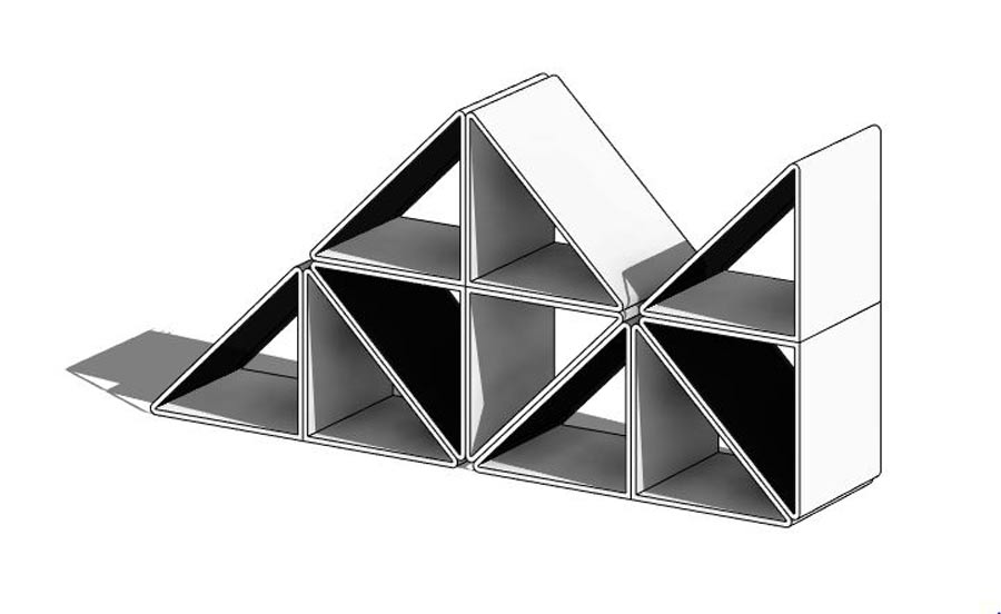
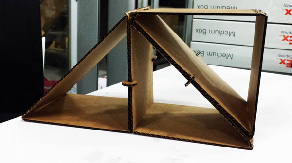
DESIGN-MODEL
I don't know how to materialize my final project yet, so I wanted to do something simple and useful for this moment like a cardboard shelf.
MODEL
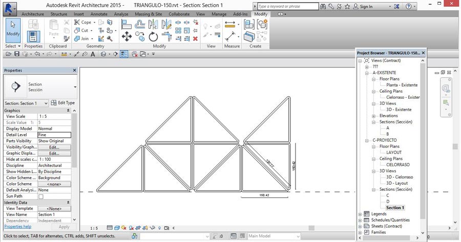
I made a simple model in Revit that can be modified very easily.
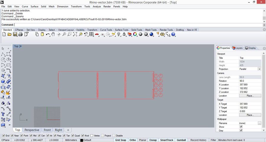
VECTOR
I made the vector design in Rhino.
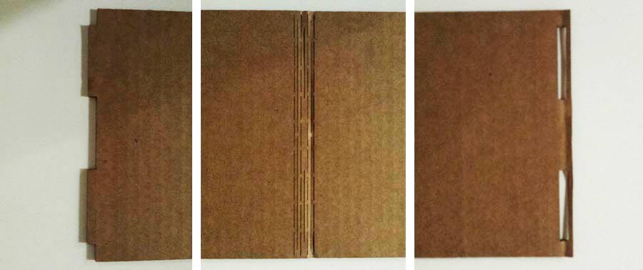
MAKE
Cardboard (3mm), Lasercutter (Epilog XT Legend 36 75w):
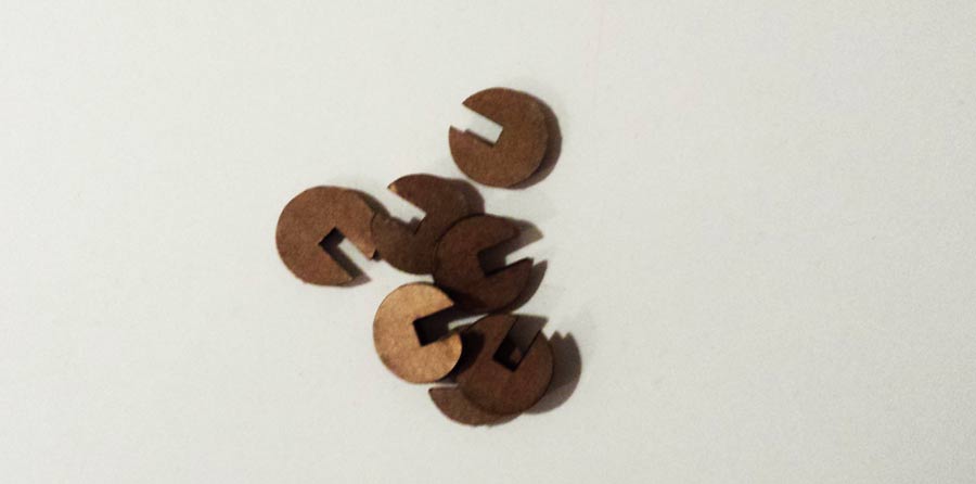
JOINTS
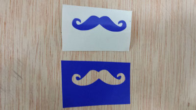
VINYL CUTTING
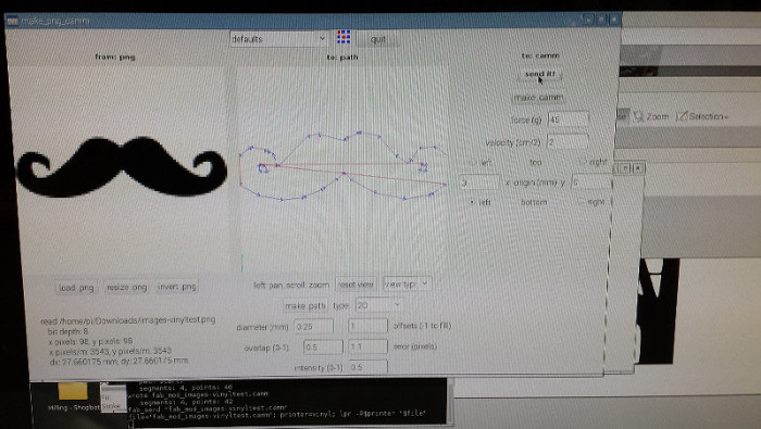
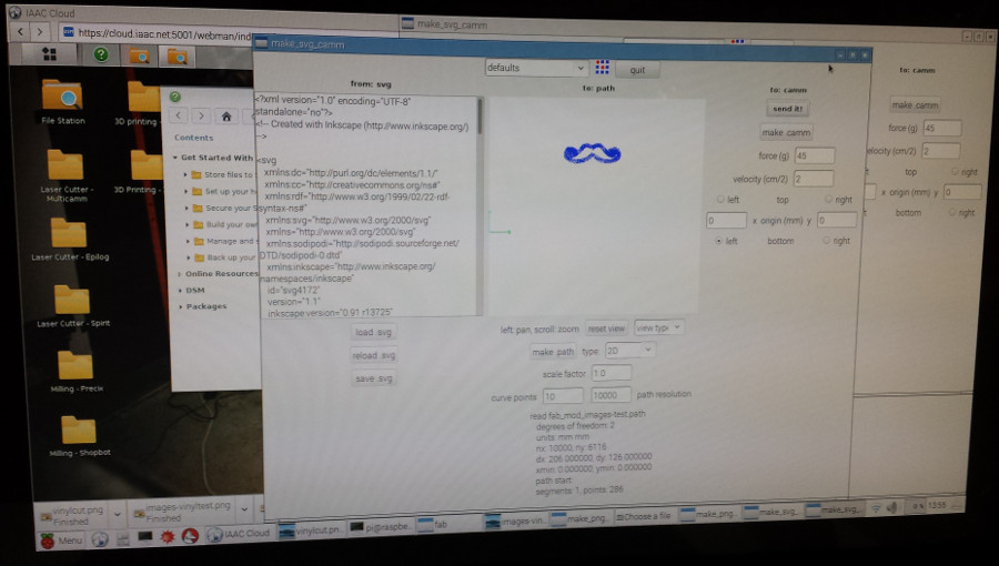
At first I only wanted to try the machine, so I downloaded a png image. I sent the file first as png but it didn't looks good, so I opened it in inkscape and set up the canvas with the dimensions that the Roland Vinyl Cutter gave me, I saved the file as an svg and I sent it to print using the fabmodules to generate the g-code (make-camm).
STEPS:
1-Set up the Roland
2-Open fabmodules
3-Open the file (choose the format)
4-make path
5-choose the material to cut
6-make.camm
7-send it

Download files
Download revit file
home