CNC Hot Wire Foam Cutting Machine
1 Introduction.
2 Initial Concept.
3 Existing solutions.
4 Hardware Design.
5 Electronic Design.
6 Software Solution.
1 Introduction
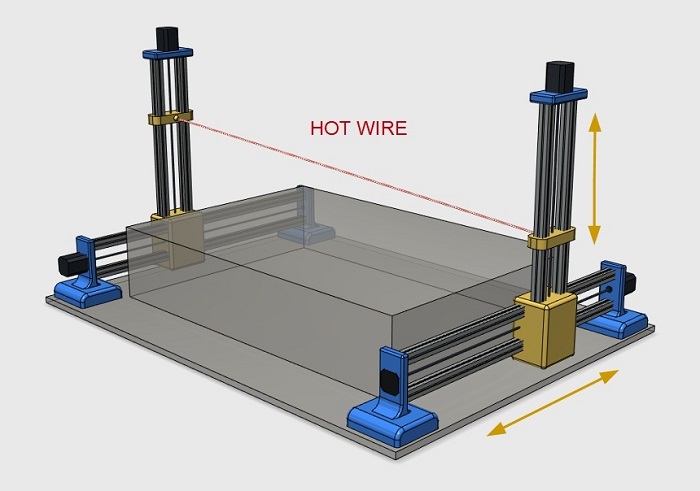
The CNC foam cutter is a machine controlled by a PC computer capable of cutting any 3D objects out of extruded and expanded polystyrene foams (EPS and XPS). The cutting is performed with a hot cutting wire moving in the vertical and horizontal axes through the use of stepper motors controlled by an electronic controller connected to a PC and controlled with our unique software. This ensures flawless precision, high processing speed, and consistently excellent quality.
The functional objective of the machine is to be able to cut irregular designs, that is, the profile of one side is different from the other.
Background
As a lab manager I must be attentive to the processes, activities and needs of Lab users, most of the users are students of mechanical engineering, electronics, aerospace and product design.
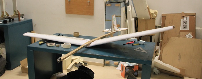
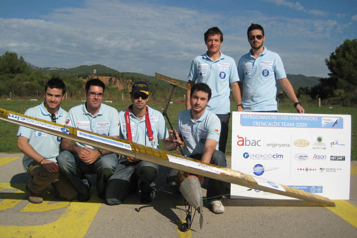
In work carried out during this year we have detected the need to have a foam cutter to manufacture wings quickly.
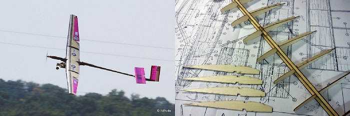
In the Lab we have helped in the manufacture of prototype rc aircraft through the tools we have, the prototypes have been manufactured in a successful way but the manufacture of the wings requires a lot of time. What makes the test flights are a real challenge especially for the rc pilot as it faces an unknown plane, in the first flight always crash and the wings are the ones that suffer the most breaks. We need a faster way to fabricate wings.
2 Initial concept
Design tips:
Replicable.
Control the hot wire tension.
Initial testing with arduino.
Temperature control.
Design and manufacture of PCBs to replace some standard components..
Comply with safety regulations and occupational hazards..
3 Existing solutions
We can find the industrial machines and the machines maker. Here are some examples and details
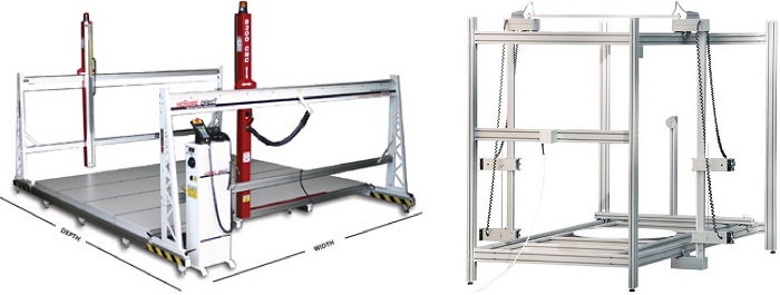
Indsustrial machine
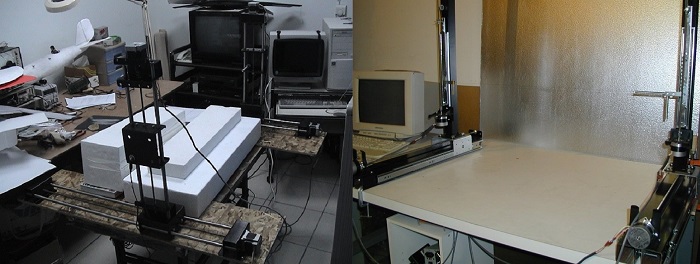
Maker machine
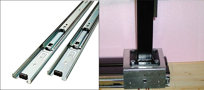
Maker machine guides and tower link
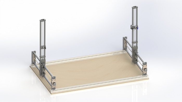
4 Hardware Design
These are the main parts of the machine-hardware.- Base.
The base is important because on it we will fix all its parts which are interrelated. Poorly fixed parts can lead to poor calibration. A machine like this should not be transported continuously but still must be.
- Estructure and guides.
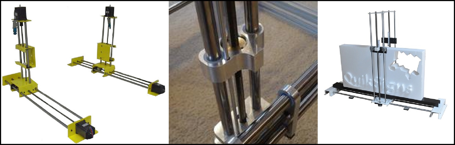
Some machines use the steel rods guides as a structure. In my opinon it limits the high of the Z axis towers, The rods can flex due to the weight of the Y axis or the tension of the hot wire. Other machines use extruded aluminium profiles systems like macaduino wich has a lot of accesories and offers an excellent precission but is an expensive system The more simplest systems uses Drawer Slide for the Y axis.
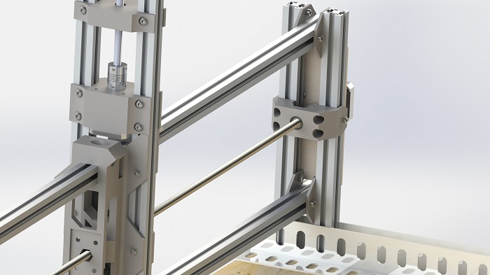
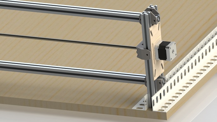
- Axis Carrieage.
Most of them are metallic elements attached to the axis guides and the lead screw
- Linear movements elements.
Lead screw.is most used, dont need to be tighted and are cheaper than a spindle wich are more accurate.
Belt drives are the other option, the beltts get degraded often.
Lineal Bearings
Mechanical design concept.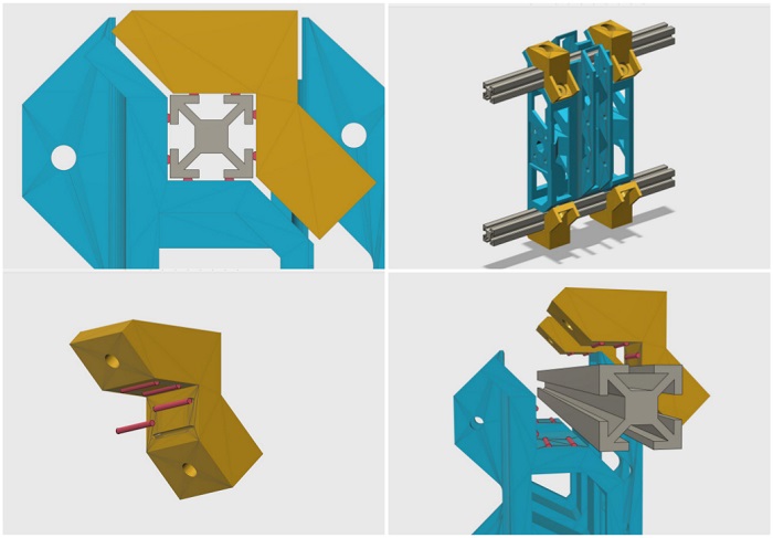
One of the concepts to emphasize in the design of the machine in the use of the structure as a linear guide. The cars will move on the same structure using as element antifriction small segment of tribo filament. This filament is up to 50 times more abrasion-resistant than standard 3D print materials.
Here you can see the.Tribo filament data sheet.