Week 3: Computer Controlled Cutting
Make a Press Fit Construction Kit & Vinyl Cut
For the assignment we have to laser cut a press fit construction kit & cut something with the vinyl cutting machine. I searched for inspiration, thinking about making a shelf, a lamp or a laptop case. I then decided to just make a simple toolbox to have the time to experiment with the prototyping of my final project.
Vinyl Cutting
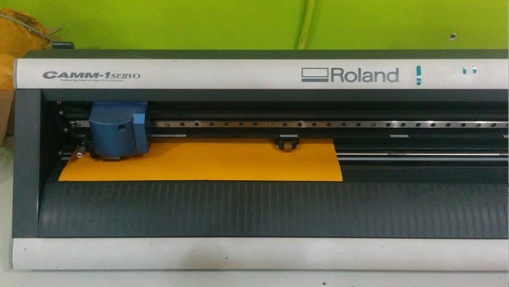
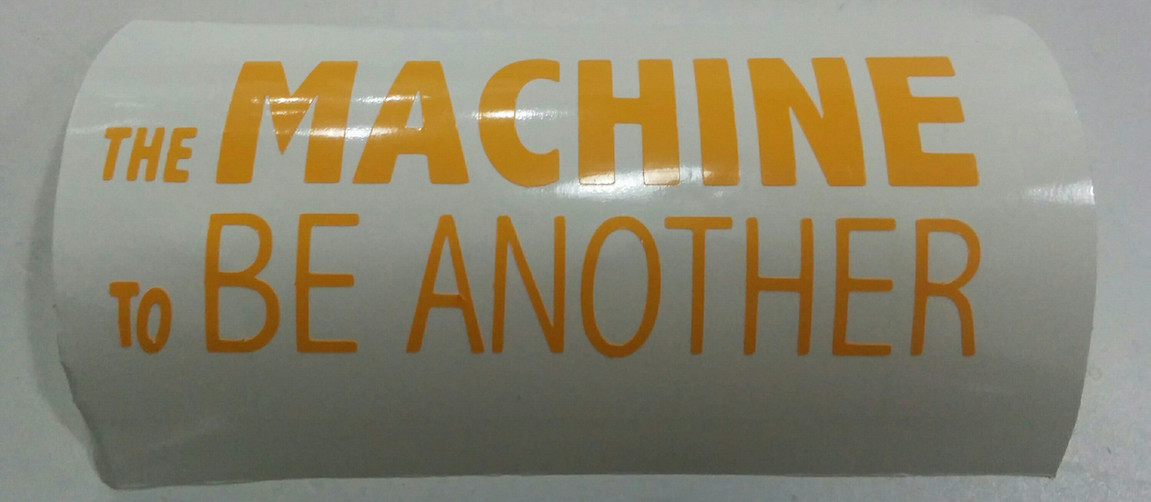
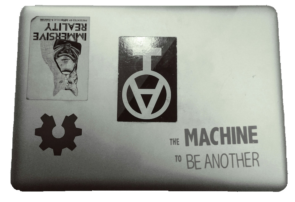
I used a b/w .png image, the logo of The Machine To Be Another by BeAnotherLab. I opened the file in inkscape, selected "path" --> "trace bitmap". I then selected the second tool from the top, which opens a new tool bar on the top of the menu. Here I chose the tool that looks like a "knotted eight" to see the amount of knots. Now I selected "path"--> "simplify". I then combined all lines and saved the file as an .svg. This file I opened in the CutStudio software, which prepares the file for the vinyl cutter, a Roland xxx machine. The vinyl material is entered from the back of the machine and fixed with the black handles. Turn machine on and navigate to material "piece". In CutStudio click on properties "get from machine", which will send the material size to the software settings. Click cutting and off it goes.
Introduction Laser Cutting
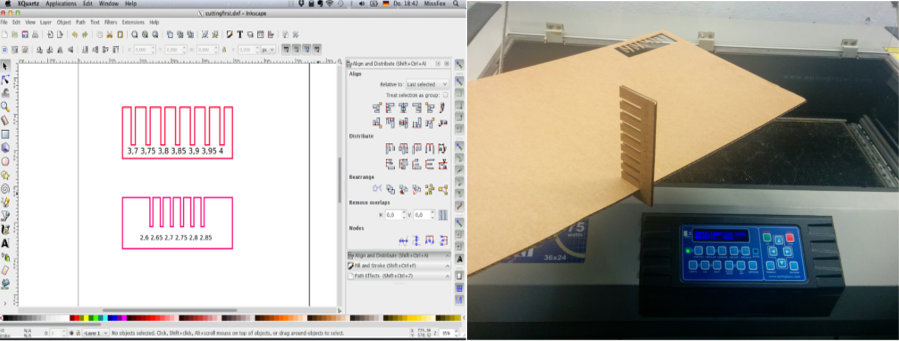
In our introduction to laser cutting we modeled a comb in Inkscape for a first demonstration of the machine. To generate the comb we created a rectangle shape (size 40x100 mm) and added five more small rectangles (width all in mm: 2,6; 2,65; 2,7; 2,75; 2,8). We aligned (top edges) and distributed (center equivalently horizontal) the small rectangles and combined them (path → combine; or ctrl + k). The objects are now transformed into one object (in difference to the “grouping” function, which maintains their separation, but allows to modify them simultaneously). Convert object to path. The next step redefines stroke style and taking away the filling. Important to have settings on 100% opacity and full alpha, otherwise the laser cutter won´t cut out the object. Then we moved the small rectangles onto the top of the bigger one; next selecting path→difference→ subtract (or ctrl + -), deletes the small rectangles, creating the comb shape. Safe file as dfx.
Making a Parametric Toolbox: Boxmaker
Material: Cardboard
Laser-Cutter: Epilog Legend
Software: Gimp, Inkscape (plus extension box.maker), Rhino
I downloaded the boxmaker extension for inkscape and watched this tutorial. Boxmaker lets you determine the box shape (see image for size details) and automatically generates the joint/tab outline as a parametric design. All side-defining lines are generated as individual objects, so I had to combine each box side and rearrange the objects on the canvas to save material.
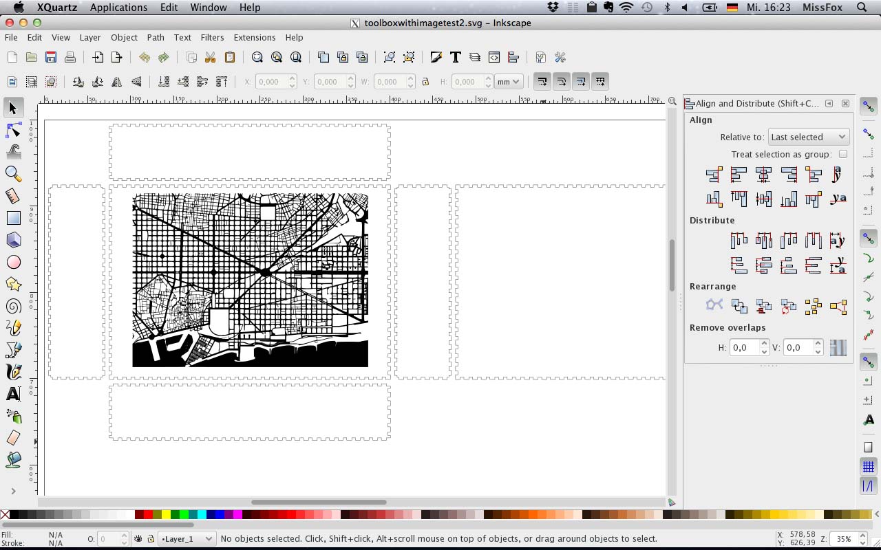
I added an image of Barcelona´s grid to the box for engravement. I copied the image from Google Search into Gimp and reversed b/w colouring with the magic wand tool (wand--> select --> invert and bucket fil tool, safe as .png) Then I copied the file into Inkscape and turned it into a vector image (path-->trace bitmap). File safed as .dxf file.
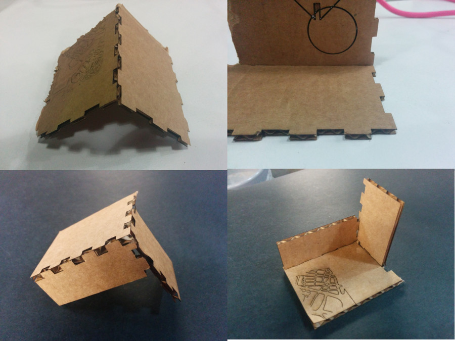
I did two test cuts of box corners and a part of the engraving to adjust settings: I decreased the kerf from 0,8 mm to 0,25 mm and changed the tab width from 10 mm to 0,5 mm. I hope this would increase stability. The space between parts remained 5mm. The test parts were cut with a laser setting of 100%power and 18% speed, the engraving was set to 100% speed and 40% power.
I uploaded the file to IAAC´s filecloud and opened it in Rhino on the computer connected to the laser cutter, Epilog Legend (work canvas size 900x600). I checked if the setting is in mm and "joined all"(select all --> type join in command line). In the bar on the left I checked proportions again and set mm. I chose "vector" in the properties and opened a window "tap colour mapping" to set the engraving/cutting order in which the laser cutter does the job. The colour hierarchy determines the chronology of the job, engraving needs to be done first. Colours need to be set in pure colours (red, green, blue, etc), otherwise the machine doesn't recognise it. I went back to print, save and set design to "home", top left in Epilog.
On the laser cutter itself I pressed buttom #8 (XY off), and confirmed with "yes" (=green button). Now I could position the laser manually. Pressed buttom #7 to "adjust home" = machine home is set. Press #9 = focus. press "go" = green buttom to start laser engraving and cutting.
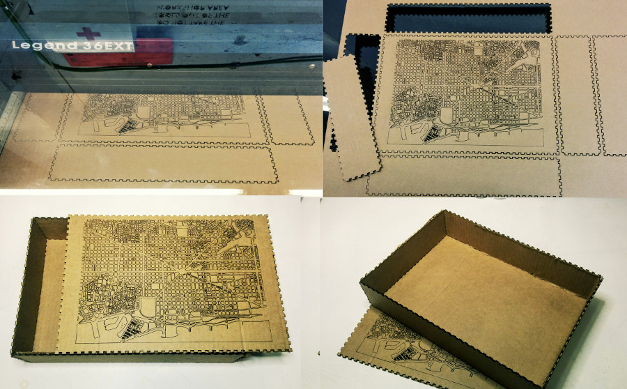
Some Result
The result was disappointing, only the engraving worked well (it took 29 min.). For cutting (took 6 min.), I had measured the thickness of the cardboard beforehand, but setting material thickness to 2,8 mm was too narrowly calculated as thickness varied between 2,7 - 3 mm. In consequence, not all pieces where cut neatly and braking out insuffiencet cut lines was neither neat nor efficent. Additionally, I had used the inkscape extension boxmaker, which failed the one job it had: defining the exact tabs to make the joints match to make the box. I could force-stick the cardboard box together, however, if the material would have been wood, the cut would have been wasted. I also did not like working with boxmaker as I felt like I was not doing anything myself, somewhat disempowering to rely on a failing extension. I only used it to get the first making of an object going quickly as I intened to prototype my final project afterwards.
I wanted to make a prototype of the shoulder structure of the e-hoodie, however, I ran out of time. I searched for cutting patterns and started drawing the design. I planned to take my size measurements and cut the shapes out of paper to glue them together, for a first materialization of the idea. Next would have been the adjustment of the shapes, and repeating the process with textile. The textile needs to be put on a figure sewing model to correct shapes again by redrawing lines and adjusting measurements. Next, the individual cutting patterns need to be drawn in Inkscape. After this first design steps, the file would go to Rhino for test cuts.
Designing a Parametric Toolbox: Antimony
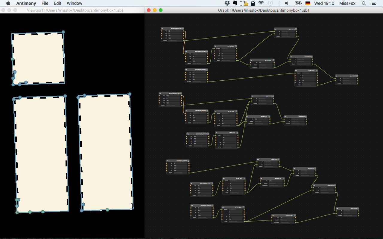
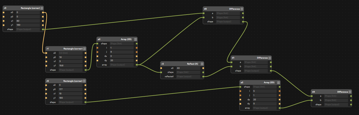
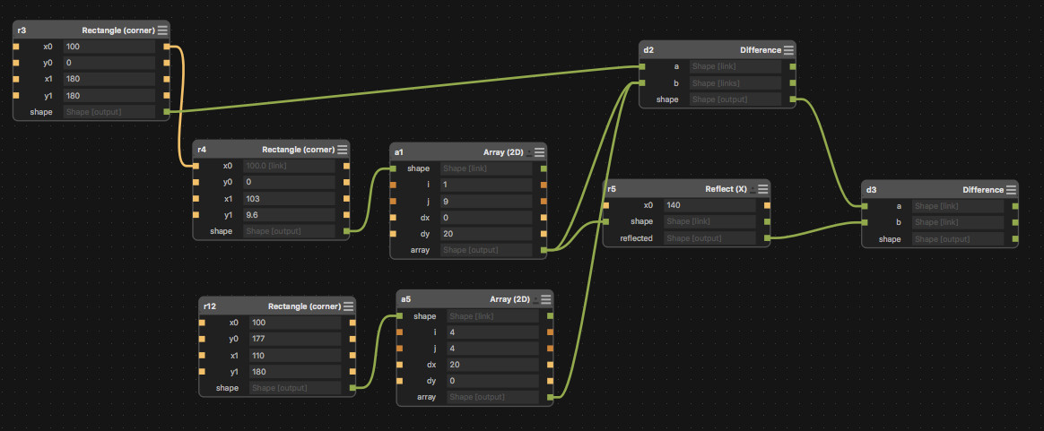
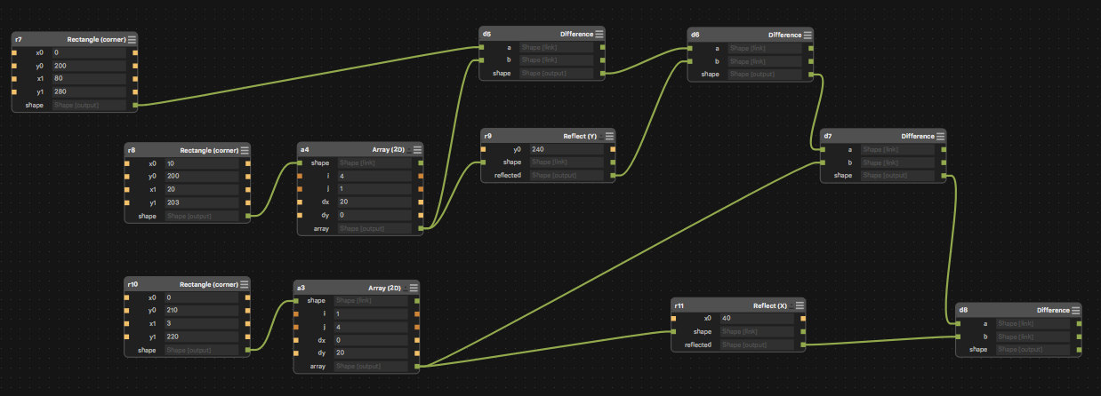
I tried antimony for a parametric design, downloaded the antimony.dmg file.Opening the software just shows two windows, open new file and click edit which opens tool options. Commands are familiar from Rhino, but the workflow was completly new to me. Basically each command generates a box in which allows to individually modify values for x/y. Design is linked by connecting "shapes".
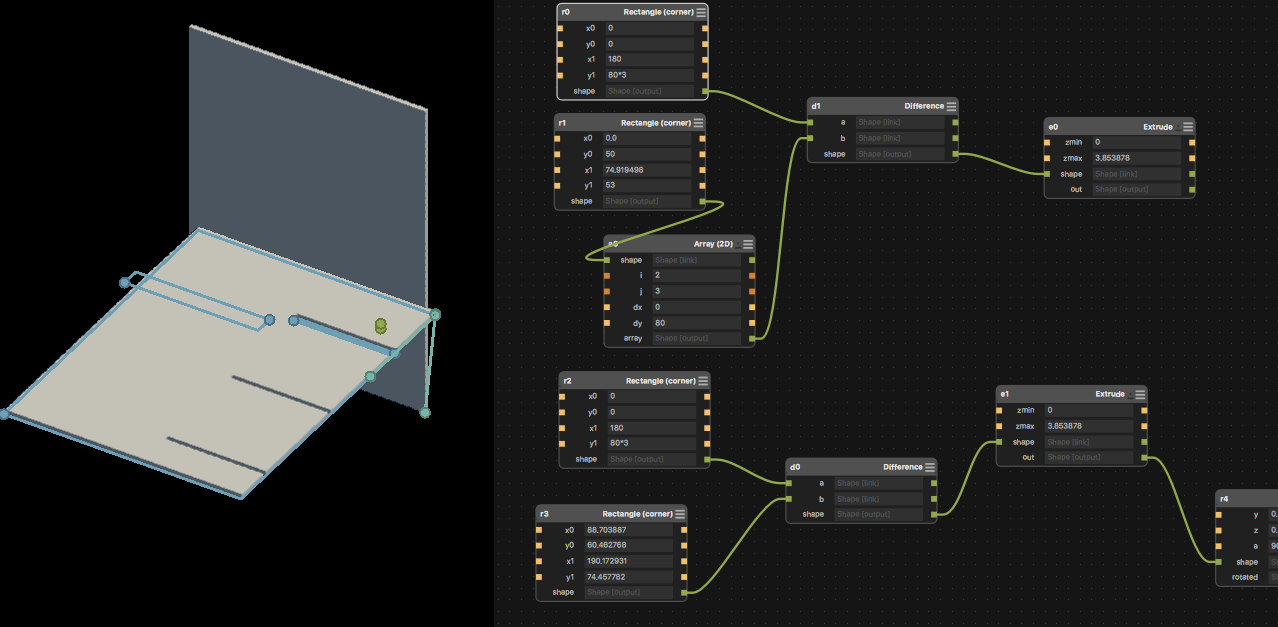
Started a new antimony file, aiming to make a simple 80x80x180 parametric box. The workflow consisted of making a big rectangle (the box wall) and a small one (a tab), which I multiplied (array) and subtracted from the big box wall (difference) to generate the tabs. It´s really nice to have a visualisation of the commands, although I wonder how not to get lost in really complicated designs...this after all is just a box... I would like to try grasshopper next, as I have slowly gathered some familarity with Rhino.
Download All Files