Week 04
This is one the most exiting things I'm expecting to learn in Fab Academy. Electronics is a completely unknown ground for me. I know there's a lot of possibilities of implementation in different projects.
It is so good to be able to be doing this, I just hope to not complicate my life to much.
Objectives
Make an in-circuit programmer.
USB power, make clean, make hex,(sudo) make fuse (check programmer in Makefile, may need to repeat), (sudo) make program, desolder SJ1 and SJ2 make IDC ISP cable, connecting header pin 1 to pin 1
Check wiring.
Weekly Progress >
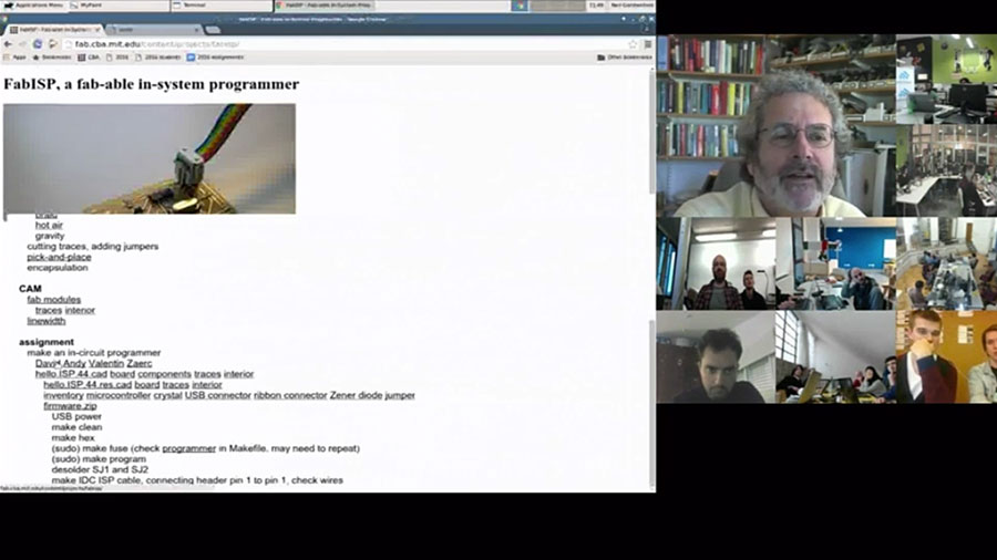
First, we had our weekly lecture with Neil Gershenfeld, you can watch it here.
Eric Pan gave this week’s lecture, he talked about electronics production.
Open source and DIY electronics are filling Fab Labs and maker spaces with new tools for incredible creations. How can we design tools to change how people make things? How to scale DIY electronics to millions of users?
Assingment >

I have to be sincere here, I had no idea how this programer works. If you are like me, a person that never heard about this before, don't get to stressed because later you will get it.
It looks scary but at the end is logical stuff, that doesn't mean that I get everything now, but you will see the amazing things you will do in the future with this.
First step is to grab the example files from Neil. You need three files, components, traces and interior (outline).
I share with you the files here
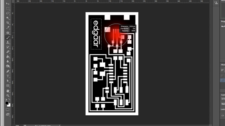
Next, modify the hello.ISP.44.traces.png file. You can use Gimp, Photoshop or any other image editor. Remember that after you finish modifying your board you have to save the image at 500DPI.
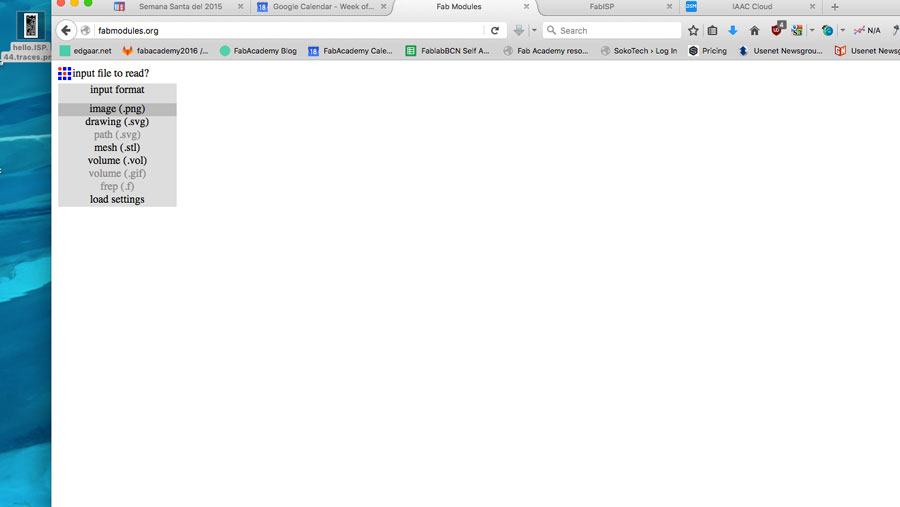
Then we start with production. For preparing the files we used FabModules which is the open source platform from Fab Foundation to prepare files for production.

Then we set this parameters:
Input format: Image (.png)
Output format: Roland mill (.rml)
Process: PCB traces / outline
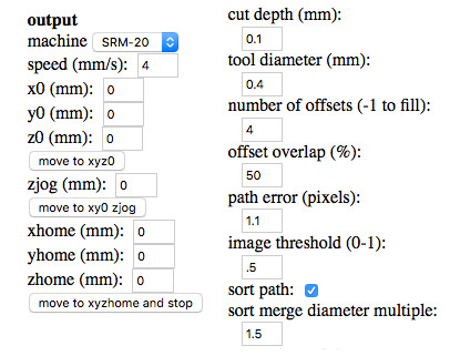
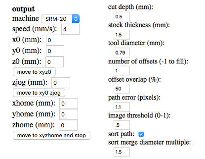
We used the SRM-20 for the milling process with this settings:
Traces
Outline

The we uploaded the files to the our Fab Lab cloud. We use this process to share files and to have available files in any computer or machine that we have in the lab.

Next you save the file in the computer connected to the machine, in our case a SMR-20. Then you open the file with the machine's program and run it.
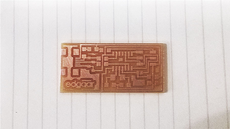
This is the result, my first board, ready to be stuffed! It took 15 minutes, more or less.
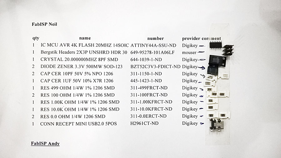
This is the BOM (Bill Of Materials) that we used for making this board.
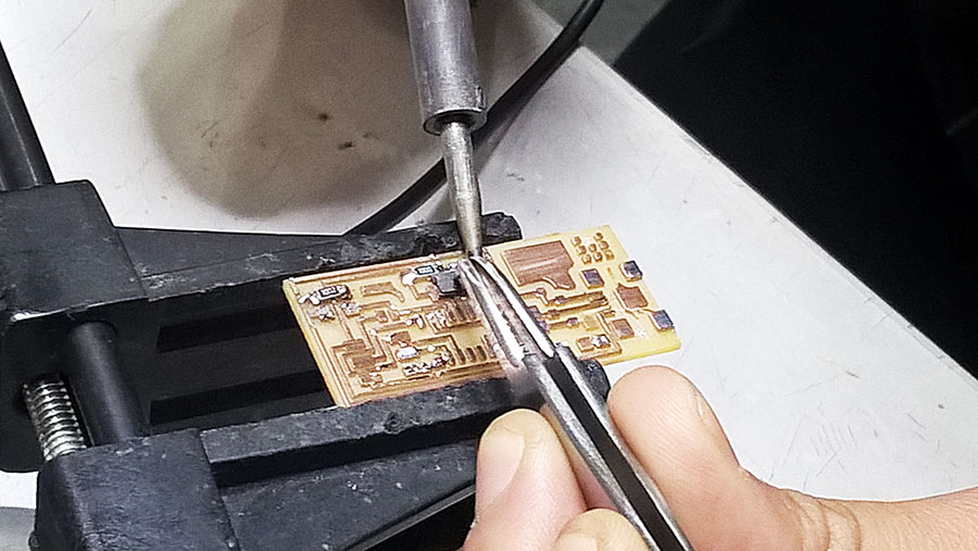
Soldering is a fun part for me, but at the beginning it wasn't that easy. My first mistake was that I wasn't leaving the solder wire long enough so the material attached really bad, Ferdi (our tutor) helped me by showing me the capillary effect off the solder wire, if you get this you will make your life a lot easier when soldering!
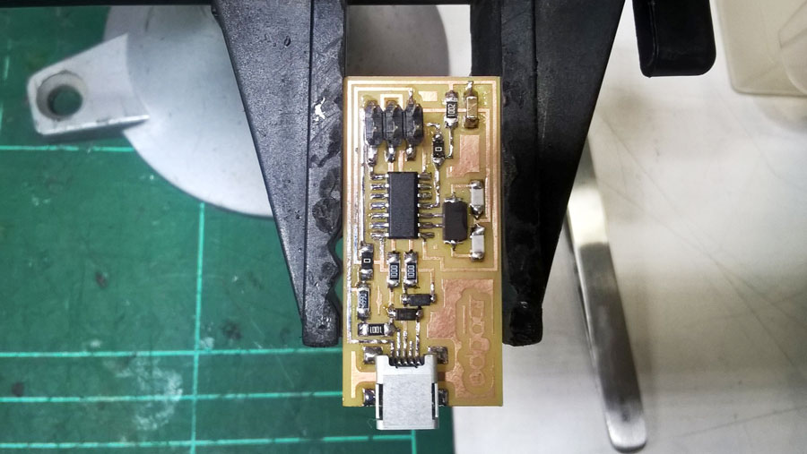
My first stuffed board!
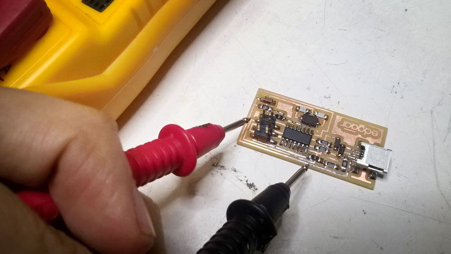
After you finish you have to check all your wiring with the multimeter. Spend some time on doing this because is a safety issue for your computer, if you don't do it and you have a short circuit or something in the board you can ruin your computer, so be careful and take your time.

Next, you have to program your FABISP, I used this guide.
This are the steps:
To program the FabISP, you first need to install the necessary software for your operating system and download the firmware.
Edit the Makefile.
Set the fuses / program the board.
Verify that the board is working properly.
Desolder jumpers to turn it into a programer.

For programming I used the ATAVRISP2.
This are the steps (for Mac):
First step is install the Crosspack AVR
Get Xcode (If you don't have it)
Get Make (via Xcode)
Get FabISP Firmware (MacOS 10.8.2 - current)
Connect the AVR to the computer and the FABISP to the AVR (In this step you will know if you have done your board correctly)
Then go to the folder where you put the FabISP Firmware and run this make clean.
Next type this make hex.
And then this make fuse (so your board can use the external clock).
Then we program to finally make it a ISP with this make program.

I had some problems with a bad connection, so the when I was trying to program, I just got an error message. Because of this bad connection the computer couldn't find the FabISP.

If you have done everything correctly, you will receive a success message!
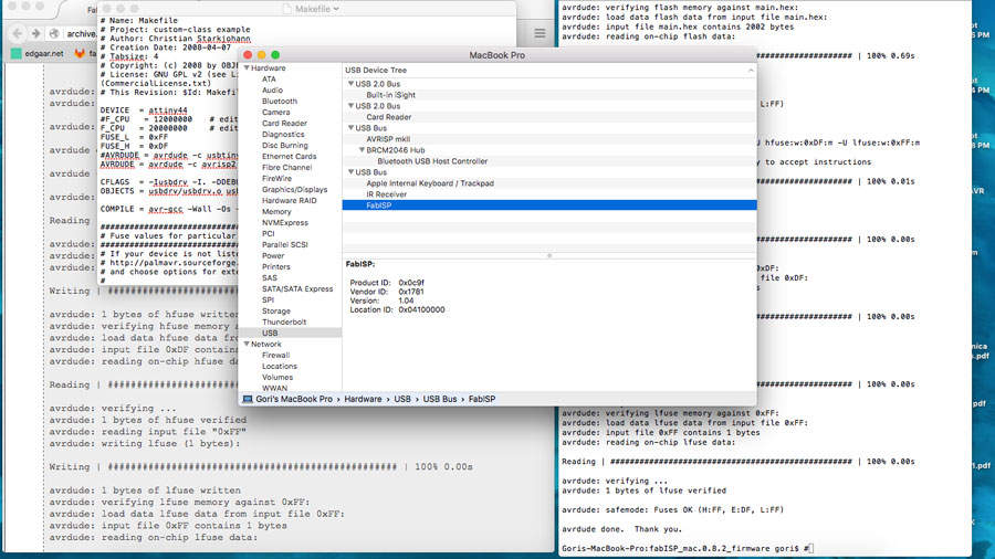
And the last step is to check if your computer identifies the FabISP. For doing this go to About this Mac > System Report > Hardware > USB, there you should see FabISP listed.
That's it you are done!
