Week 11 - Input Device
Assignment:
- measure something: add a sensor to a microcontroller board that you have designed and read it
- This week’s home work page
"Luizino":The whole goal of this week for me was to create my own Arduino Version (Luizino) and use it as well as my input device. The reason I'm doing this is for later use this board for my final project, probably giving it more pins and a shield.
One of the things that make this project special is that I´m using an ATMEGA32U4, that has FTDI integrated, so you can, after burning bootloader, program your board using an USB Mini B. The ATmega32U4 is the same microchip used on Arduino Leonardo.
I based myself upon many designs out there. I used the Eagle Schematics from the Leonardo itself, from the Xduino 8.0, the ATmega32U4's datasheet, Fagan Terence's page as inspiration, Jonathan Grinham's FabLeo which I had to access via WAYBACKMACHINE, and a lot of Ferdi's help (Our Guru here at Fab-Academy Bcn).
Luizino is a simplified version of an Arduino. No reset button, just one led on pin 13, an ICSP for its first programming, some Pins but not all available. I designed it to be easily hacked.
Let's start:
The ATMEGA32U4:There you go, the beast!
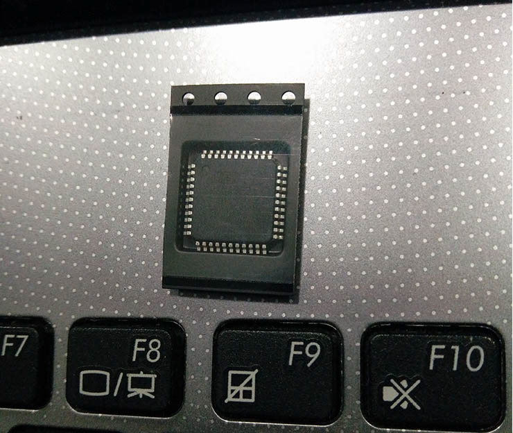
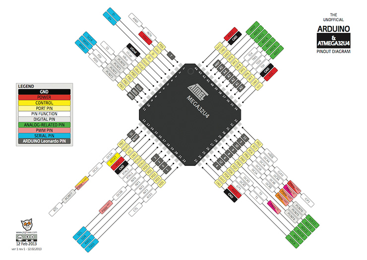
I found this image which is Very helpful, knowing what is what in your ATMEGA32U4.
Thank you pighixxx.com.
As you can see, the grey frame is the pin scheme exactly as they are in Arduino Leonardo, making it easy for you to program it afterwards with Arduino IDE.
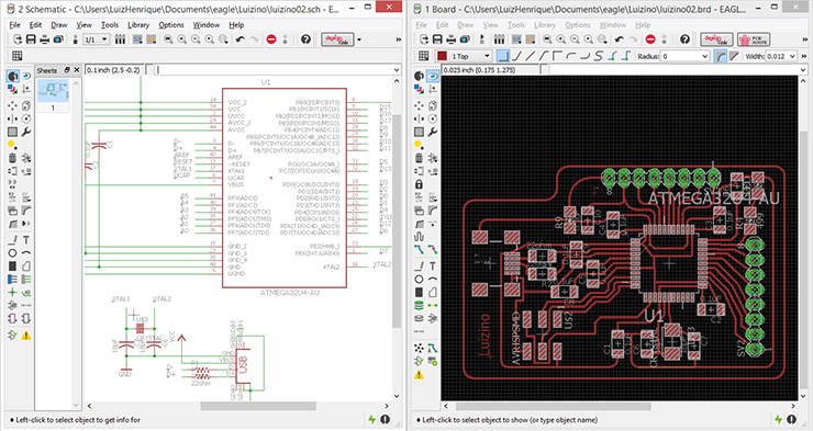
Designing in Eagle:
As I mentioned all the sources above, the FabLeo was the one I started from.
The hardest part was to find out what all the components were for, in order to be able to change the design.
Luizino ended up with half the size of a FabLeo.
Bill of Materials (BoM):
Partlist exported from C:/Users/LuizHenrique/Documents/eagle/Luizino/luizino02.sch
Part / Value / Device / Package / Description
-C1 0.1uF CAP-US1206FAB C1206FAB
-C2 0.1uF CAP-US1206FAB C1206FAB
-C3 0.1uF CAP-US1206FAB C1206FAB
-C4 0.1uF CAP-US1206FAB C1206FAB
-C5 0.1uF CAP-US1206FAB C1206FAB
-C6 18pF CAP-US1206FAB C1206FAB
-C7 18pF CAP-US1206FAB C1206FAB
-C8 0.1uF CAP-US1206FAB C1206FAB
-C9 0.1uF CAP-US1206FAB C1206FAB
-C10 0.1uF CAP-US1206FAB C1206FAB
-LED LED1206 1206
-R1 22ohm RES-US1206FAB R1206FAB Resistor (US Symbol)
-R2 22ohm RES-US1206FAB R1206FAB Resistor (US Symbol)
-R4 499 RESISTOR1206 1206
-R6 680 RES-US1206FAB R1206FAB Resistor (US Symbol)
-R9 RESISTOR1206 1206
-SV2 MA08-1 MA08-1 PIN HEADER
-SV3 MA08-1 MA08-1 PIN HEADER
-U$1 USB_MINIB USB_MINIB USB_MINIB
-U$2 AVRISPSMD AVRISPSMD 2X03SMD
-U$3 CRYSTAL CRYSTAL 2-SMD-5X3MM
-U1 ATMEGA32U4-AU ATMEGA32U4-AU QFP80P1200X1200X120-44N 8-bit Microcontroller with ISP Flash and USB Controller
It's Milling Time:As you might already know, to mill our boards we are using fabmodules.org, and for that I exported my files as PNG, one of the formats that FabModules opens.
You might want to save it in very high resolution (around 700dpi) so your traces get very precise once fabmodules converts it.
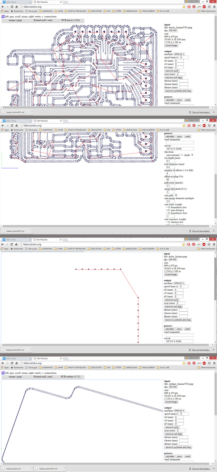
For more details on how to better use the milling machine, please go back to my week 04 - Electronics production, where I explain it with a lot of details.
Once the files are all converted into gcode, it's then time to mill the board.
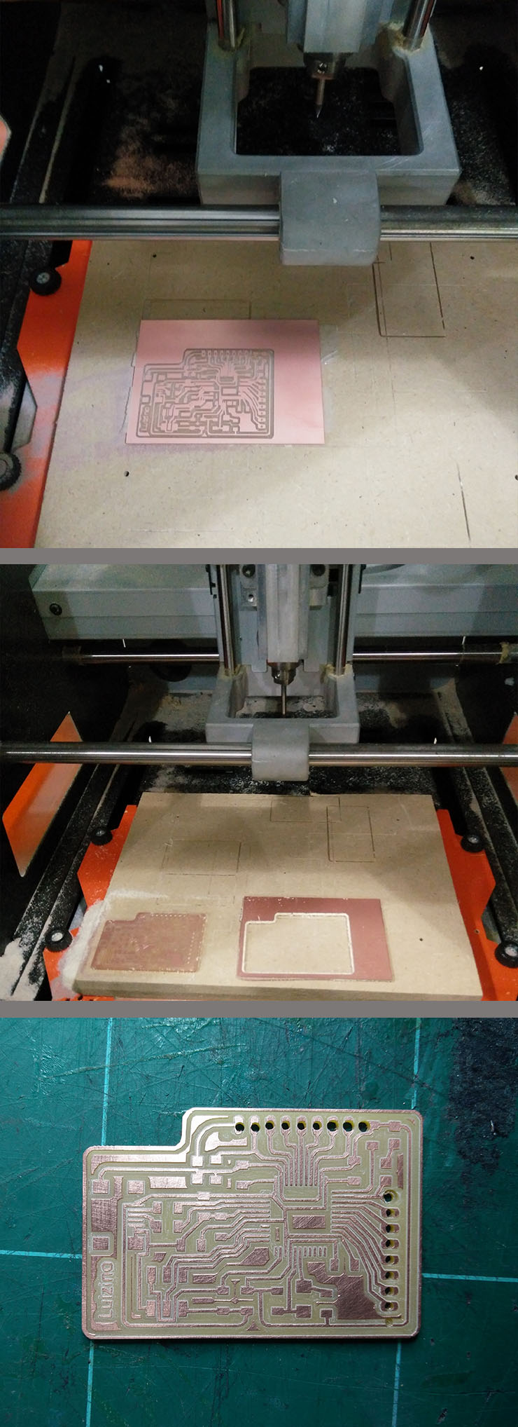
It look gooooood!
I know the holes are bad, but at that point, all I wanted to do was to make sure it would work, so the pins were my last preocupation.
Check out how Luizino would look if I would be able to perfectly solder the microchip:
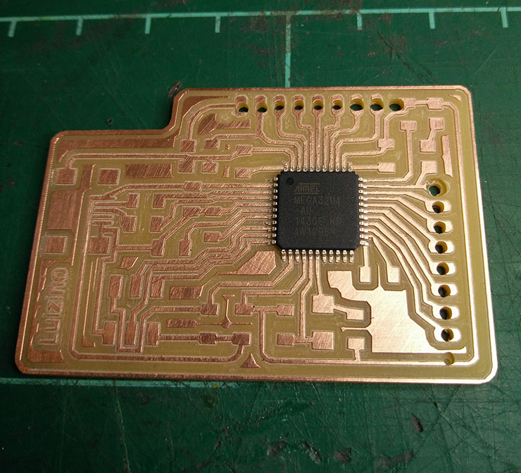
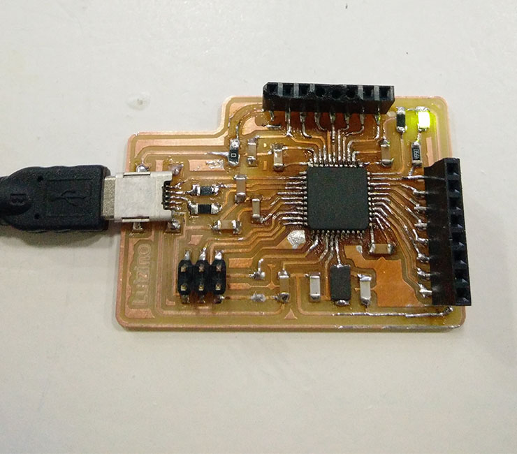
Stuffing:...and that's how it went:
Please don't judge, soldering the ATMEGA32U4 can be a nightmare.
I'm calling it Artistic and so it's easier to carry on.
I ended up doing it with a soldering iron without flux. A bit of respect, please. But I started soldering it with a hot air gun. I was not careful enough and I got a blister on my board. Once it cooled down, the blister shrank back. Lucky me it was enough to continue.
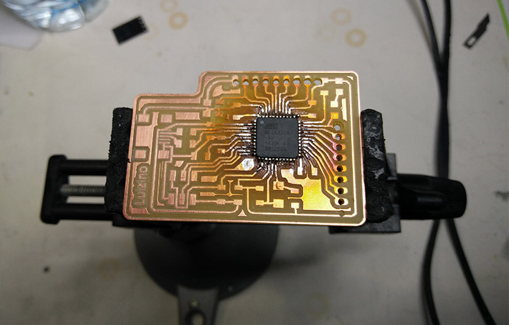
In this image, it still shows some of the mistakes I made. The Resistors close to the USB are supposed to be 22ohms, as the datasheet suggests. After I read the datasheet I corrected it. That was basicly the reason it didn't work to program it the first time. As well as the resistor bottom left, it is just not supposed to be there. It's removed from my board now.
Needless to say this consumed a lot of time, right?!
Programming the Luizino: As I mentioned above, many things went wrong. With an AVRISP programmer we got orange leds blinking, meaning there was something wrong. After checking the connections carefully (again) with a multimeter, I found a leg of the microchip not properly soldered.
This time, with my FABISP, my board was recognized.
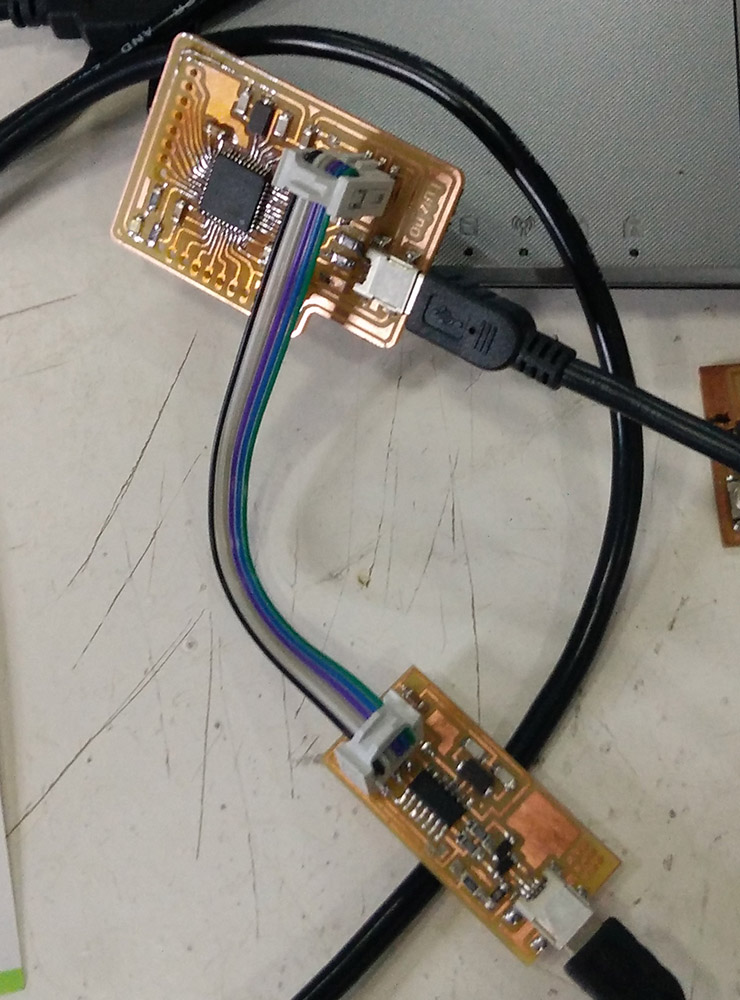
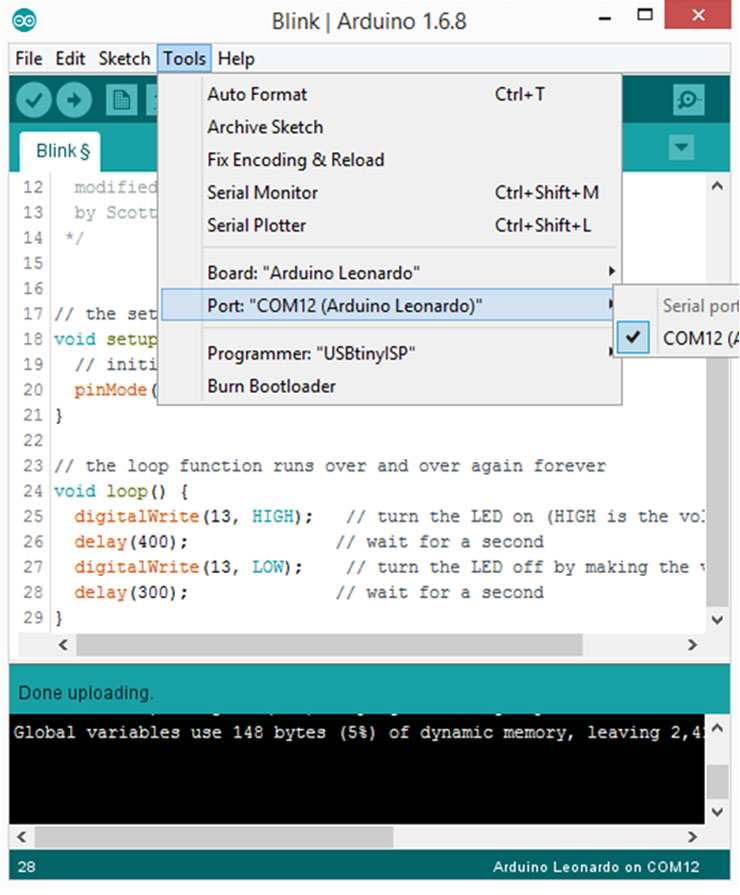
I used Arduino IDE to program it, plus my FabISP. Once the Luizino board was recognized, in Arduino IDE, select Tools menu, Board: Arduino Leonardo (Leonardo Board has the same ATMEGA32U4), Then Tools again -> Burn Bootloader.
It worked! So now I can plug Luizino Board with an USB mini.

To test Luizino, first thing I did was to run a Blink example. I made sure to place my LED on pin 13, just as Leonardo's Board. It was just opening the example and uploading it.
.
And the best part is to see it working. Fireworks!!!
That is a great thing I must attribute to FabAcademy. 3 months ago I would have never being able to do what I just did. Not even close ;)
It is a great feeling, I must admit. The board works.
Now lets get to the week's task.
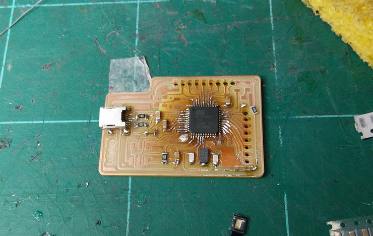
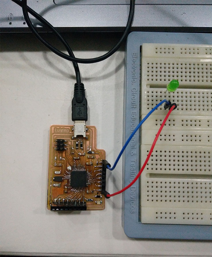
LED as Input Device:LED stands for: Light Emitting Diode.
But what not everyone knows is that the other way is also valid. To, instead of applying current to receive light, applying light and to "produce" electricity.
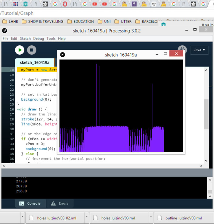
For this experiment I used Luizino Board (Pin A0) 2 wires and a LED. I ran the example AnalogReadSerial (The very first example from Arduino IDE's library).
With Arduino's IDE Serial Monitor I could already capture some influences in the result once I placed my mobile's phone flashlight. Thanks to Ferdi's suggestion, I installed Processing and I ran the Process Arduino Graph code to give me a proper monitor with a graphic. It was beautiful to see the results and I'm sharing them here:
Files:
Before downloading the files, some friends told me they were having problems to download it. It worked when they logged into their googledrive account. If the Eagle files extension comes different to "brd" or "sch", just rename it and write "brd" to the board one, or "sch" to the schematic file.
-Luiz-ino Board EAGLE -Schematics & Board- files (Up-to-date Version)
-Processing Arduino Graph Code
(For the Luiz-ino file, this is the 3rd version of it. In this version, I added 5 extra pins. Among them are the SDA and SCL, needed for I2C connections.)