Week 10 - Machine Design
Assignment:
- make a machine, including the end effector
- build the passive parts and operate it manually
- document the group project and your individual contribution
- This week’s home work page
Laser cutted robotic-arm, servo assisted...continuing:This is a project I started with 2 other colleagues of mine Andreas Markwart - Electronics, and Julian Peschel - Graphic Design. This project is current and once we finish it, it'll become a DIY Kit as introduction to electronics and robotics.
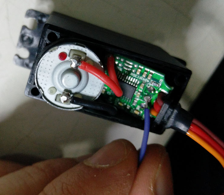
One of the things that make this project special is hacking the servos. It is simple, open up your servo motor and solder a wire to the signal of the potentiometer inside of the servo. Every servo has a potentiometer inside of it. Find the signal wire and solder your extension wire. With an Arduino, I loaded the code "ReadAnalogVoltage", I powered the servos end with the wire plugged to "A0" pin, I could easily read the voltage of the servo's potentiometer. Spin the servos Axis to see what is the output that changes the voltage. That's your signal.
This "Servo's Output" will serve to give you the location of your arm at every point. Also to later tell your robotic arm to go to a desired position, having then full control of it. At least is what I expect.
I like the concept of the pygestalt from Nadya, but I felt like going my own way, using the code Andreas is coding. I'm putting effort to understand it and working with it, so this will be used for my final project.
I also believe our way is much easier (Again, that's the goal) so that also excites me.
What we have so far are the servos controlled by joysticks, using Vector calculation to control the arm's position.
Material needed:
Arduino pro-mini;
FTDI Cable to connect your pro mini (I used an Arduino Uno without the chip as my FTDI)
02 Joysticks
04 servos 15Kgs High-Torque
01 micro servo 2.2kgs (Clamp)
buttons
wires
solder
screws (M4 Nylon 25mm, M3 steel 8-10mm)
access to a laser cutter
3mm MDF 500x500 mm sheet, or acrylic (Better)
access to a 3D printer (You could also do the gears in laser or milling)
5v external power supply for the servos
Patience
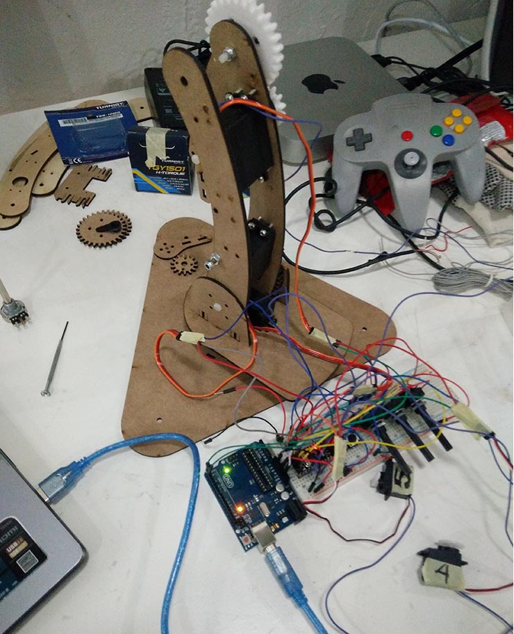
That doesn't look too good if you compare it with a PCB properly designed for this task and all wires organized, but for the time being, it is the best because this configuration will still change a lot.
Can you note the Arduino Uno without the microchip? Below you can for sure.
Did you also note I 3D printed some gears? They are better than laser cutted.
This is what we're using, it's a version of an Arduino Pro-Mini:
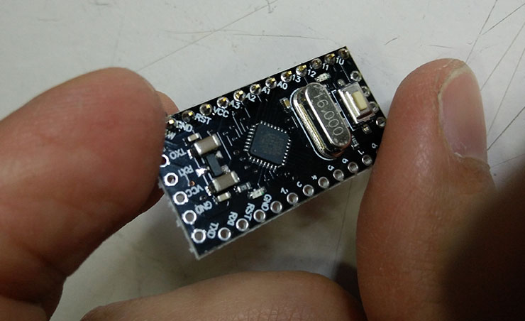
Note it doesn't come with an Usb port. The Arduino Pro-Micro has one, with a bigger microchip with FTDI included.
If you have a FTDI cable laying around, use it, otherwise check out the tutorial on how to use an Arduino Uno as a FTDI.
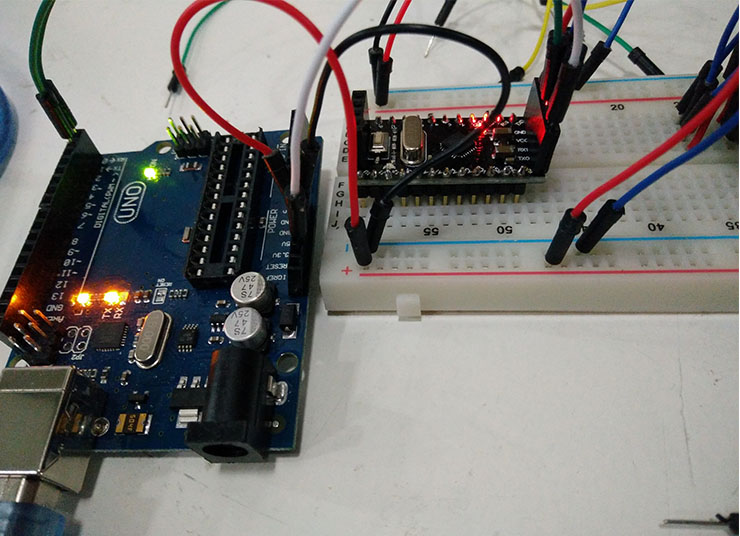
What I did after that was to solder the pins to the pro-mini according to my need.
One solution is to plug it to your breadboard. I didnt do it cause I had a feeling I'd melt the plastic of the breadboad due to the solder's heat.
That is a great thing I must attribute to FabAcademy. 3 months ago I would have never being able to do what I just did. Not even close ;)
It is a great feeling, I must admit. The board works.
Now loading the programming file in the Arduino IDE and wiring it all.
ASSEMBLING 5 AXIS ROBOTIC ARM:
-Servos: 3 connections + 1 (Gnd, VCC, Signal & Servo Output)
As the name suggests, we are using 5 servos. In this project, the 5th servo controls a clamp or accionates a gadget. Only 4 servos for movement.
These servos must be connected to an external power supply, the Ground and the VCC.
Signal wires will be plugged to:
servo 0 = Base Rotation base - Pin 4;
servo 1 = Shoulder axis - Pin 5;
servo 2 = Elbow axis - Pin 6;
servo 3 = Wrist axis - Pin 7;
servo 4 = Clamp/Action servo - Pin 8;
const int firstServoPin = 4;
Servo Output wires will be plugged to:
servo 0 = Base Rotation base - Pin A0;
servo 1 = Shoulder axis - Pin A1;
servo 2 = Elbow axis - Pin A2;
servo 3 = Wrist axis - Pin A3;
servo 4 = Clamp/Action servo - Pin A4;
const int sRead[5] = {A0, A1, A2, A3, A4};
-BUTTONS: Menu button, Select 01, Select 02
There’ll be 3 buttons and they will be plugged to Pins 11, 12, 13 (and ground of the Arduino, obviously).
const int buttons[3] = {11, 12, 13};
-JOYSTICK
2 Joysticks - potentiometer style
They have 2 potentiometers each. We’ll control Axis X and Y with one and Z and Action/Clamp with the other.
Each Joystick has 5 contacts. GND, VCC, Potentiometer01, Potent02, button.
const int sticks[4] = {A5, A6, A7, 10};
-Download my files::-Ulearn 05 Axis Robotic Arm Arduino Code
-Drawing Files Rhino and DXF - Robotic Arm