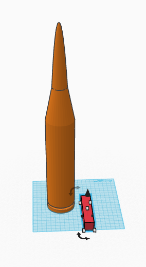
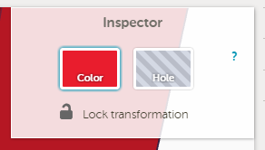
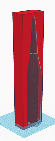
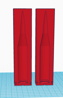
Then, since I wantd a 3d model of the mould, I switched the merged model to a hole, which would allow me to embed the shell into a block to create a half mould. This is done by selecting the type of material with the button below.
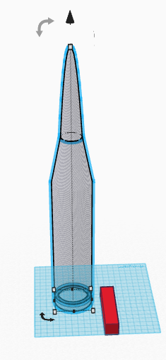
I then embedded the shell into a solid block, making sure to have the edge of the bock perfectly on the center of the shell and that the block is deep enough to accomodate the shell half. This made sure that my shell would not be oddly shaped after moulding.
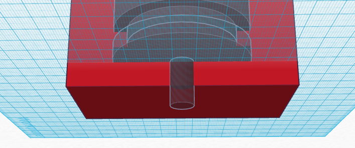
I then added a hole to the bottom of the mould for me to pour the moulding material into. If I were thinking, I would have added a vent hole to allow air to escape while I poured the moulding material into the mould. I added one later with a drill. I also should have chamfered the hole to allow for easier pouring, which I also did later with a drill.
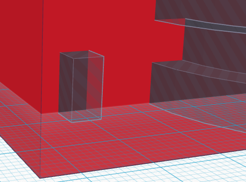
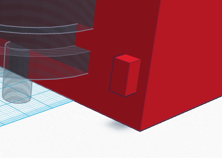
I then added pins to the bottom to allow me to fit the mould together properly. I should have made them larger, because the broke off shortly after machining. They were also too small for the bit I used which widened the female pins and rounded the edges. I made the female pins first, since I would swithc the pin holed to solid after copying the mould.
I then merged everyhing together again, creating one half of a mould. I then cpoied the mould and unmerged it so I could swith the holes to the male pins. I then re-merged the second mould to create the other mould half.
I then exported the mould after flipping the moulds on their backs to allow the milling machine to process the mould correctly.
Machining
I decided to use the roland mill and some machinable wax to create my mould.
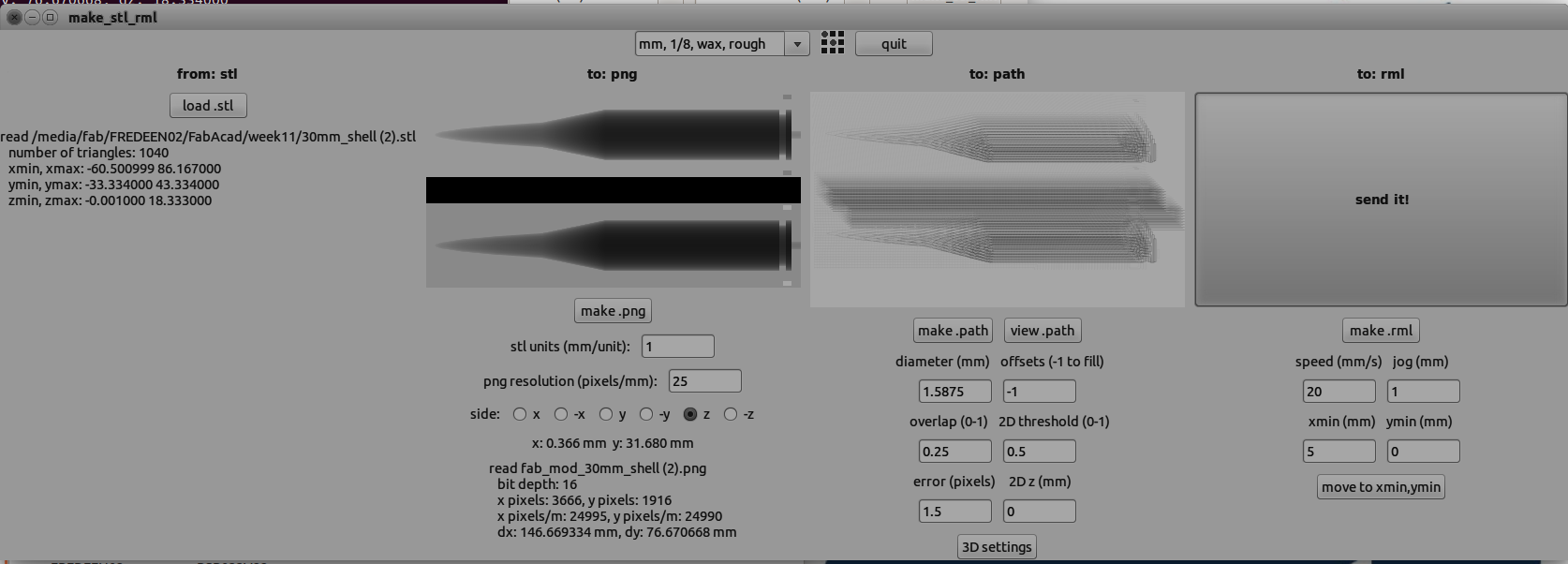
The first thing I did is move the exported stl file to the milling computer. At the milling computer I booted into Linux and used the offline Fab Modules to comvert the STL file to an RML file for the mill. I used the Rough setting for a 1/8 inch bit with the settings below. Remember to change the width of the bit in the settings.
I first put a foam block on the mill as a test to see how my mould would mill. I cut a block of foam that woud be about the size of my block of wax and hot glued it to the bed of the mill. I used hot glue because the double sided tape that I was used to would not hold the boam block during machining. I used and installed a 16th inch bit and zeroed the bit on top of the foam.
When I first ran the RML file, I discovered that I had the block of foam oriented wrong. This informed me which direction I should orient the wax block later. I reset the machine by pausing the job and pressing both the up and down buttons at once. Usually this works, but sometimes you have to reset thefab modules, presumably to interrupt the serial connection. I then reoriented the foam block and re-ran the job. I noticed nothing out of the ordinary during this run and moved onto the wax block.
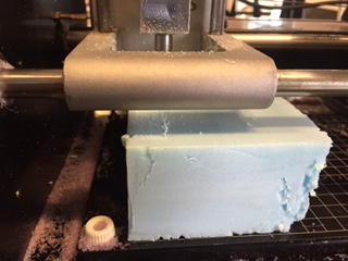
I hot glued the wax block onto the bed after removing the foam block, and re-zeroed the bit so that it rested on the surface of the block. I then ran the RML file on that block. This takes a very long while to finish, so grab a book.
Then change the settings so that the machine is now finishing the mold (making the mold more smooth). Remember to change the width of the bit if necessary. Run the RML file once the modules are done and send it to the mill. This job will take less time, but you still might be waiting awhile.
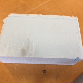
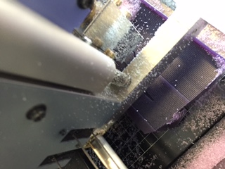
Once that job was done I removed the mould and moved the moulds to the scroll saw So that I could cut them apart and trim the edges.
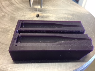
This turned out to be a mistake however, since the saw would constantly catch on the wax. I managed to get the pieces apart, but the blade broke off (on both ends!) whild trimming the ends.
I then turned to a razor blade and trimmed the edges through whittling. This allowed me to attach the moulds in a way that would have them flush with each other. Now the moulds can be filled with liquid plastic.
Moulding
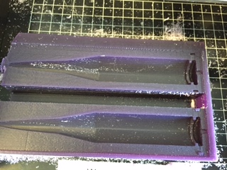
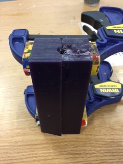
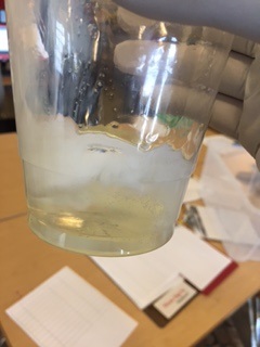
To begin Moulding, I applied release agent (fancy wax in our case) to the mould to prevent the plastic from sticking to the mould. If the casting material you choose is rubber mould material, it is definitely required. After waxing the mould, I first line the mould halves up, so that the mould is as close as possible to what I want. Recall that the pins broke off during machining, so I needed to manually line the moulds up. I clamped the moulds together with two bar clamps in a fashion that would allow me to use one of them as a rest. I also put clay onto the outer seams of the mould to prevent leakage. This can be seen on the image of the cured mould.
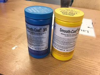
I then picked out a moulding material. I picked liquid plastic that is designed to set in 30 minutes: Smooth-Cast 305. This is a two-part plastic that sets ridiculously quickly. It produces no nasty fumes and is much safer than other materials. The two part mixture does react exothermically, so the mould will be warm duting the process.
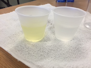
To begin using the casting material, put gloves on and pour about half of what you will need in a small cup. Pour an equal ammount into another cup. Now is a good time to check how good the batches are. Both parts should be a somewhat viscous liquid, and if not, your batch is probably expired.
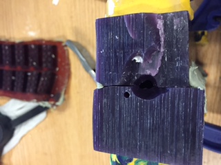
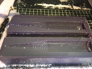
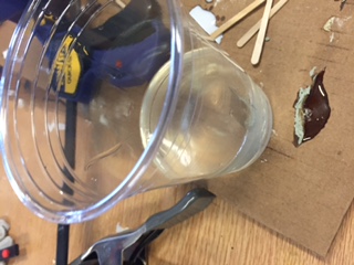
Then I puth both parts into a larger cup and stirred the mixture. I stirred slowly, to avoid the additon of air bubbles. I then carefully (but quickly) poured the casting plastic into the mould , periodically poking with a toothpick to release air bubbles. when the mould overflows, stop pouring and see if there is another mould ready to use the excess on. The image below is that of the cured mould, since I was too busy to capture the pouring process.

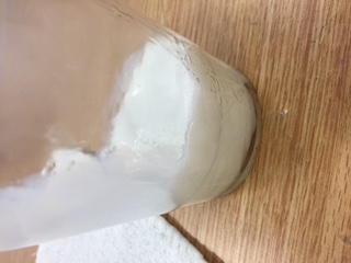
The liquid plastic that I use sets quickly, and the color change from clear to white is visible. As I said, the reaction between the two produces a bit of heat, which probably drives the reaction faster. In about 15 to 40 minutes, the plastic should be solid, but the cast may be rubbery for another day.
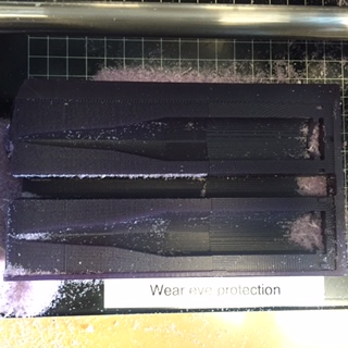
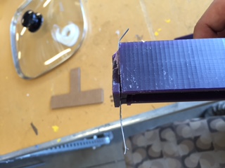
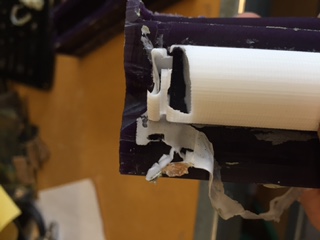
To remove the cast, I undid the bar clamps and gently pried away the wax mould. If the release agent works, this will be easy. Taking a cast out will be a little harder. I had to whack the mould a few times and pry the final product out, bending it a little in the process, but I reshaped it later. After removing the cast, I needed to remove various burrs found on the cast. I did this with a razor blade.
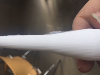
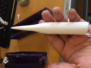
My 10 mm shell is now complete, and I have the option to sand it and paint it, but I decided to do neither.
The Importance of Vent Holes
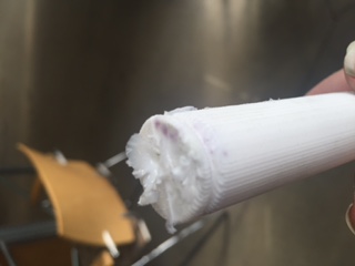
Remember that I mentioned that I hand drilled a vent hole to let air escape. I actually did this before my second attemp since the lack of an air hole ruined my first attempt. Without a vent hole, little air can escape while the casting matrial is being poured in, causing an air pocket to form near the opening.
I placed the drill near the pouring hole so air could escape easily, It didn't need to be huge, so I used a small drill bit. When pouring, be careful to avoid covering the air hole, since this could cause an air pocket to form.