I designed the board in KiCAD, with default settings. I started by laying out components in schematic view, starting with the micros. I then connected the essential components, such as capacitors, the USB port, and headers based on what the datasheet reccomends. One example of a reccomended component that I added is a 1 uF capacitor connected to UCap on the 32U4.

I then chose footprints for all of the components, saved the netlist and wired the existing components together. Then I moved on to assign headers to the remaining usable pins. Doing this last simplified the design process,since doing the headers at the same time as the other components could cause wire layout to be difficult.
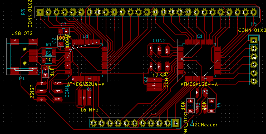
I exported the board to an SVG and thenopened that SVG in Gimp to convert the image to a high resolution black and white PNG image and exported that to Adobe Illustrator, where I rasterized the PNG for the laser cutter.
Production
I ran the laser cutter at 50% power and speed on some blank PCBs with masking tape on them. the laser cutter etched away the parts of the board I didn't want to be copper, so that the remaining tape would resist the chemical etching process. I ironed the board a few times to help adhere the tape to the board more permanently.
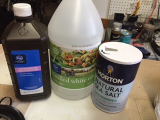
At home, I mixed a 50-50 mixture of hydrogen peroxide and vinegar together. I added some salt to help accelerate the process. This mixture dissolves the exposed copper, leaving behind a circuit. The process takes some time to complete, and varys on the ammount of copper, the strength of the ingredients used, and the quality of the laser etch.
When the etch is done I removed the board from solution and washed off the tape and any remaining solution. I then drilled holes for components and cut the bosrds out If I needed too.
Soldering was straightforward. I sanded the board down to remove any oxidation and before soldering a component I add some solder flux to the pads. If you don't sand the board, solder joints will be difficult to make later on.
Programming
I programmed both chips with a FabISP using the Arduino IDE. I burned the 32u4 bootloader first and then programmed the chip with whatever code I had written for the board on that occasion. I would do the same for the 1284P next, but I did not use that chip for much in the end.
Since I planned on using this board to communicate with other boards and the computer it is connected to, the code would probably include both I2C and serial communication.