The aims for this week were to:
1. Design and make a corrugated cardboard press-fit construction kit
I went into this week not completely understanding what parametric drawing was all about. At the end of the week, I was struggling to get my data out of my computer and onto the laser cutting table.
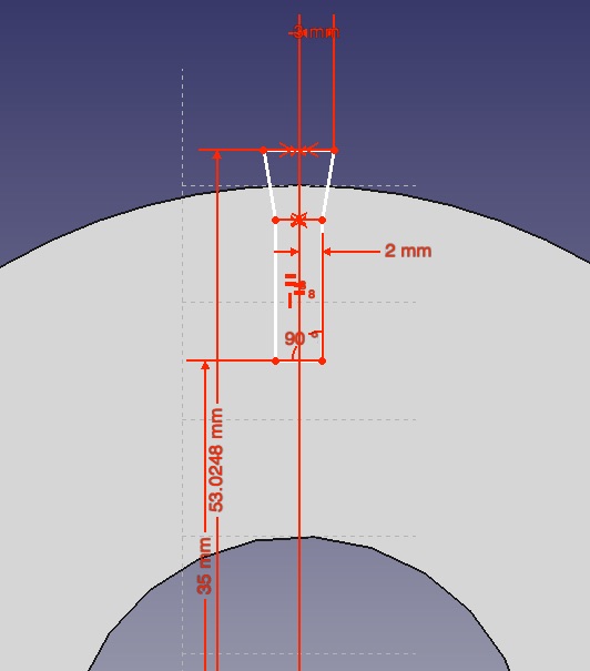
Constraints is the word that anchors it for me. The two types of constraints, are geometric and dimensional. I learned how to apply dimensional constraints with Freecad.
Freecad was a good way for me to learn to make dimensional drawings, because its reasonably clutter free, and the tutorials I found on YouTube, are detailed right down to how to use the mouse. MarthamEngineering and bram de vries are both pretty good examples.
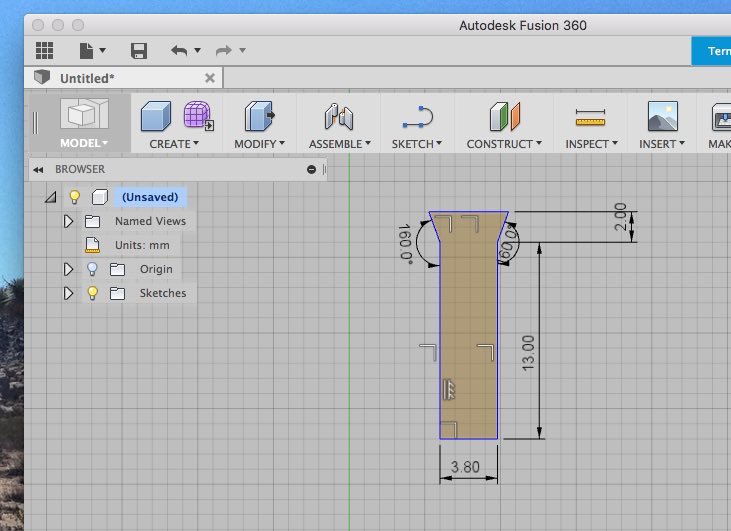
Fusion 360, while far more daunting, due partly to the unfamiliar layout, is definitely more efficient. I will be learning more about Fusion360 in the future
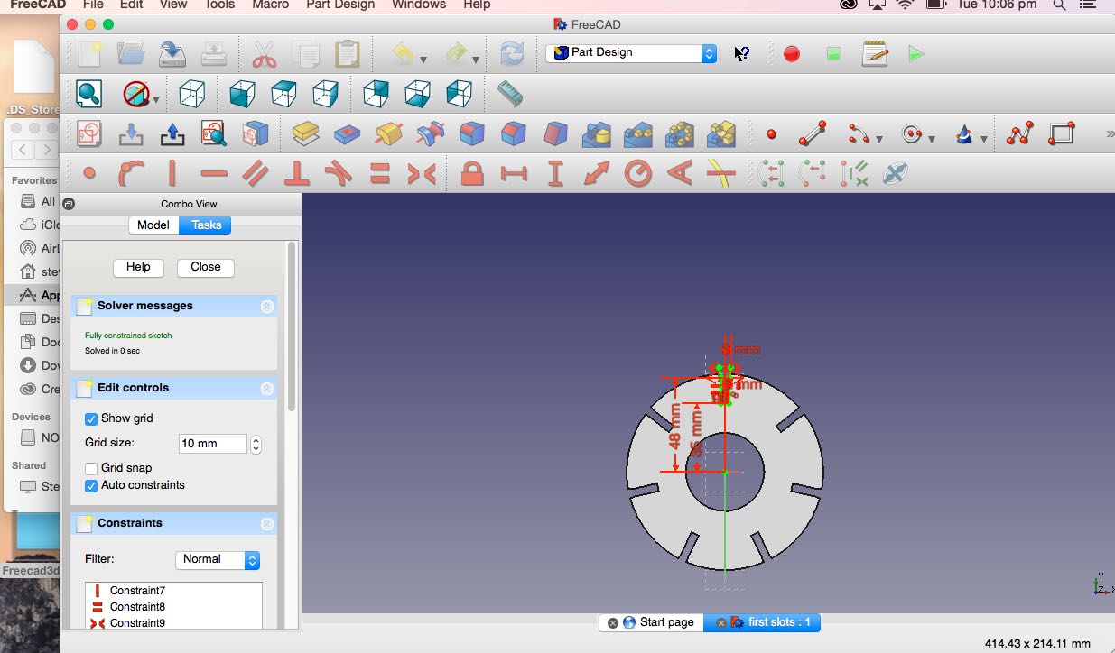
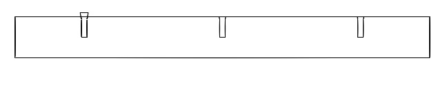
After making the dimensional drawing of the slot fully constrained and happy, I moved onto the geometric constraints. Freecad has tools to help with this. I used the Polar pattern and linear pattern tools for this job.
 My first Import/Export problem was that Freecad needed more files that don't come with the original Freecad package, this was because of licencing complications. So I downloaded the files and took ages trying to find out how to install them. The documentation wasn't particularly helpful. I eventually stumbled into the macrons folder with them, which worked. After getting the Freecad file exported as .dxf, I discovered that Inkscape changes the document size. Since I was starting to get problem solving fatigue, I was searching for a far too complicated work-around, which ground me down further. The solution came from two more experienced Fablab friends, who suggested I make a 100mm by 100mm object in Inkscape, then open it in Illustrator to find the percentage difference. Bingo, I multiplied the document size by 354.685394 give or take a few fractions. The final hurdle was that when the documents were imported to Illustrator they had lots of compound paths. I reduced that problem by selecting only the relevant surfaces from the original Freecad model - rather than selecting everything for export. Finally, once in Illustrator I cleaned everything up with Object - Rasterize - Image Trace, then with the Pathfinder dialogue box I selected Merge.
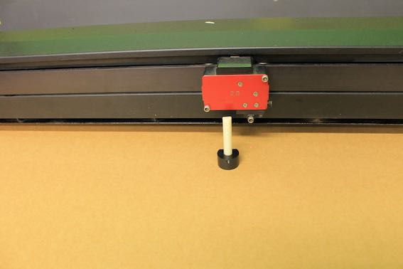
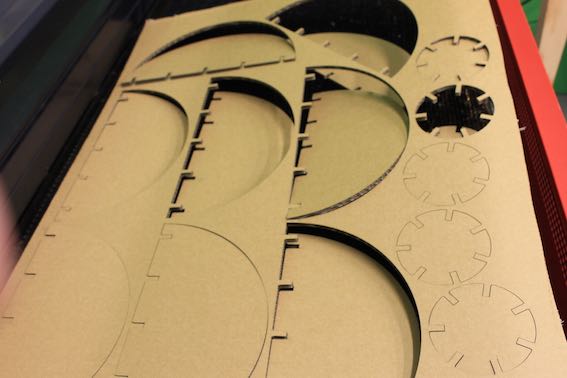
First I started up the air extraction systems. Then focused the laser by driving the bed up to a mark on the measuring stick. Focusing the lens is a bit like focusing a magnifying glass to find the optimum concentration of heat. The air extraction keeps the dirty gas out. That helps prevent the mirrors and lenses being damaged.
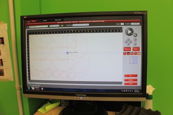
The next job was getting data to the Cam system. Our machine is the Universal ILS 12.75 Platform Laser, which is well supported by the manufacturer with comprehensive manuals , which I found useful. The Cam accepts Illustrator format files directly.They need to be 0.1 line thickness, paths must be closed and free of compound paths. I used the raster tool in Illustrator, then Image Trace to clean up the compound path problems I was importing from Freecad. After that I closed the paths using the Pathfinder Merge tool.
Next I set the cut speed, heat intensity and pulse. My settings were: 55 power, 12% speed and 315 ppi for the 3.8 mm cardboard.The power and speed settings can be ajusted in relation to each other. That means raising the power or lowering the speed to achieve the same result. The pulse per inch setting gives the same ppi regardless of speed or power.
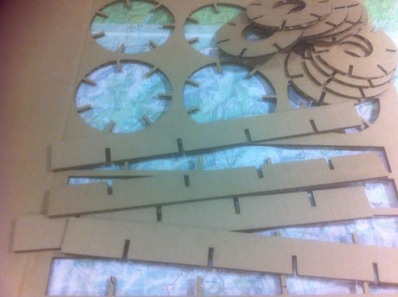
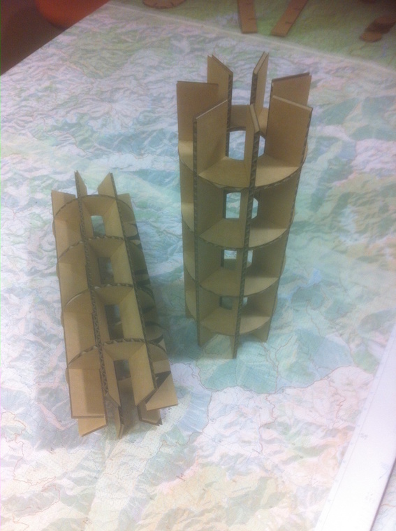
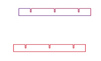
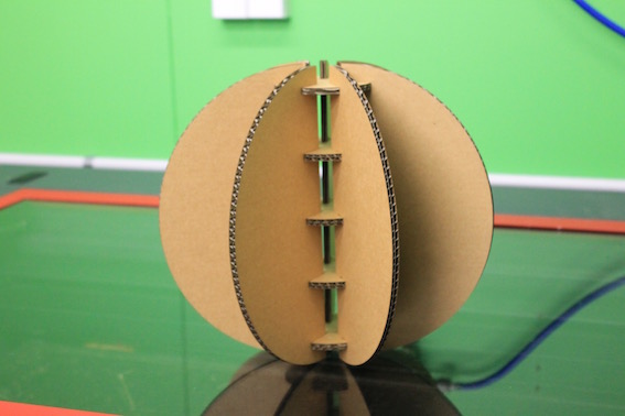
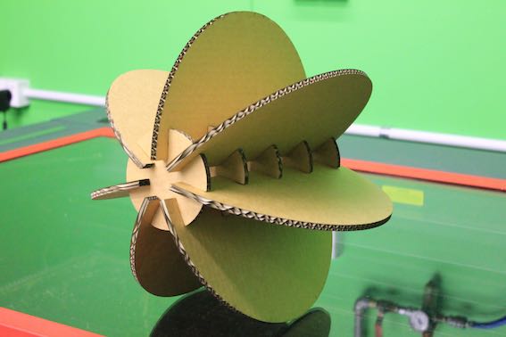
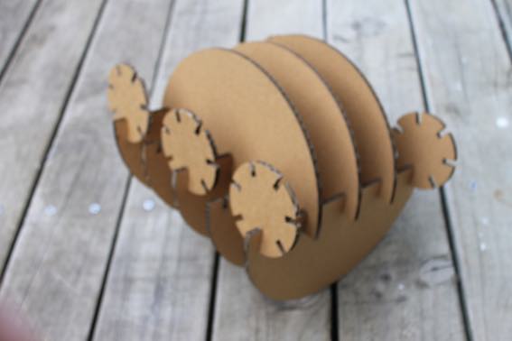
I made a set of rectangle and round shapes out of 4.5mm cardboard which was slotted and this held together nicely. Then I went back into Freecad to make half rounds and increase the slot sizings to fit 6.5 mm cardboard. This didn't work so well. My workflow was improving so the half rounds didn't take too long. But when I went to increase the size of the slots on the previously drawn round shapes, I discovered that I had used an overly complicated set of constraints which made resizing difficult. I learned how important it is to use elegant constraint design in parametric drawings.
My construction kit is not as interchangable as I would like, but I've run out of time so I'm going to have to move on for now.
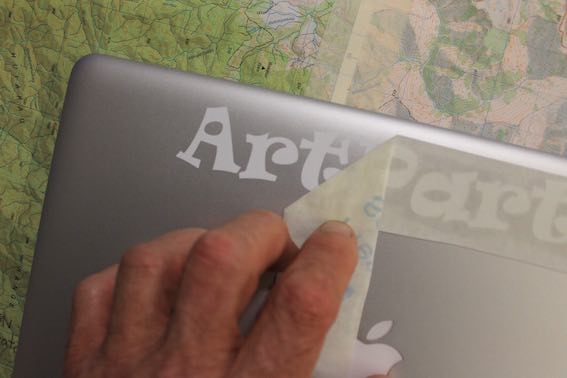
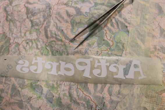
I made a sticker for my laptop computer which inspired me to explore the vinyl cutter's potential more. I am particularly interested in finding out how far it can be pushed to the outer limits of its intended use, by using the fab modules rather than the manufacturers' drivers.
Here is the official manual for our fablab vinyl cutter.The manual is a good reference for general cutting and trouble shooting. For more adventurous work which I am yet to explore, we can use the fab modules.