Steven Fett
Fab Academy 2016
Computer Controlled Machining
Embedded Programming
Computer Controlled Machining
Make Something BIG (on a CNC machine)
Files
CDR
Week 7
I drew my concept image in Sketchup a few weeks ago. This file will not be included as I lost it. Worry not, I used only this screen shot to reproduce the entire project in Corel Draw. Let us begin our adventure.
There are many ways to build a bike rack. I was looking for a way to build one while taking up as little space as possible. Considering the rack would end up inside one of the buildings I wasn't terribly worried about security. I took a look at my company's logo and began drawing letters that followed the shape and scheme of the logo. Making my letters 24 inches tall and 30-36 inches wide.
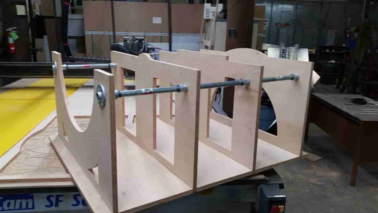
I had remembered I had two four foot by eight foot sheets of nicely finished birch plywood. I designed around using three quarter inch plywood. Having designed the letters and adding a notch and slot fitting it was time to reinforce the Letters. I added vertical struts at the ends of the letters to insure that they wouldn’t break during normal use. Normal use being when the front tire of a bicycle is lifted and placed inside the rack.
I added a temporary 3 inch holes and at one point a 2 inch holes on the ends of the letters. I was planning on attaching PVC or ABS pipe to the letters for reinforcement and aesthetic purposes.
Using the Clipping and merging tool in Corel allowed me to create complex objects out of simple geometry.
I had to consult with a friend who knew much more about bicycles than I do. What is the average height of a bicycle’s front forks from the ground? What is the average width of a bicycle's front forks from outside to outside? Considering everything from Street Bikes, to Mountain Bikes, to Fat Tire Bikes. Eight to nine inches seemed like a good number to use.
I set the average spacing between my letters to 8 inches. At this point my design work was pretty much complete. It was time to start chasing down materials.
After visiting the hardware store, I decided to use half inch galvanized steel instead of ABS or PVC. I also could not find nine inch chunks of pipe, only ten inch portions. I'll have to change my design. I changed the spacing of letters to nine inches between each. This allowed me to use one-inch male-male fittings inside each letter and female-female that tighten snugly sandwiching the wood.
It's time to route. For this particular project I used an Older MultiCAM CNC router. She's an old machine but she is powerful and reliable. First process is usually measuring your material, so I did. After measuring Height, Width, and Depth of my material I must enter those measurements in Enroute. Enroute is the CAM and tool path generation software for this particular machine. Next was to import the DXF I exported from Corel Draw. Nesting is very important to effective use of material, considering this plywood is ~$60 a sheet.
After placing my parts within the rout-able area I must close my geometry. At the moment I have lines and poly arcs that sit next to each other creating a shape, but the software has no idea whether this shape is closed or open lines.
Transform>>Merge Selection>>Press OK.
Now Enroute knows what is outside and inside the object we are cutting.
We must set up our tool-paths for cutting
Tool-paths>>Router Offset.
This launches a window we will put our parameters into. We will use Router Offset as opposed to Engraving or Island Fill. Engraving will run our cutting tool directly down the center of our line, while Router Offset will cut on either the inside or outside of the line. Considering we are going to pieces that must fit together very specifically, Router Offset is the type of path we want to be using.
Our bit will be a CS Onsrud Up-spiral Single Flute Quarter Inch bit. Our Depth will be what we measured the average material thickness to be .728". After pressing the edit button to the right of our End Mill selection, we will adjust our passes and speeds and feeds. I'm looking for a clean edge finish with little shredding or blowout, so we will use 4 passes, this equates to .182" per pass (or ~3/16ths of an inch). Because this particular machine has a hand controller out of habit I set the Travel, or Feed Rate to the fastest I am comfortable running the machine. On the hand controller I will control the actual Feed Rate with a percentage, (usually %50 to %70). Our maximum plunge rate I set to 20 inch/Minute. This number doesn't need to be terribly high as plunging will be a small fraction of the job. The Colombo 3HP spindle has a maximum RPM of 18000, however Enroute suffers from a software bug. Enroute seems to be under the impression that 18000 RPM is the exact same as 0 RPM. For this reason, I set the RPM of the spindle to 17999.
OK>>OK.
We have now created Tool Paths for our Bike Rack. Be sure to zoom in and check that our paths are outside and inside the objects where appropriate.
Time to export our job to the machine.
Machining>>Output
Check our listed tool types. Should only read quarter inch End Mill, as this is the only tool we will need for this job. If everything looks good, press To File. We must save the file into a folder we can easily find later.
Let's load our material onto the table.
The Bottom Right Corner is our 0,0. This table shares its software home with its Hardware Home. This means during the calibration process the machine finds its limits in the Bottom Right Corner. This Machine as starts its jobs from the Bottom Right corner.
Let’s bring our Tool Head to our HOME (0,0 or the Bottom Right Corner) Press the button that looks like a little house (It's covered up by my finger).
This machine has a spoil board that you can screw into, but it also has a Vac System. A Vac System works by pulling air through channels that run all along the surface of the table. On top of these channels is our MDF spoil board. MDF actually allows air to pass through it. This pulls whatever material is placed on top down firmly to the table.
It appears our plywood has a nasty bow in it and the Vac System is not doing well at pulling the plywood flat. A little bit of tape on the edge... Perfectly flat now.
This is our Hand controller. If at any time the router begins Misbehaving, making Odd Noises, Smoke, or Speaks Insults in your direction PRESS THE BIG RED BUTTON. This button will immediately cut power to the Spindle Controller (power for the spinney part) and the Stepper Drivers (circuit that pushes the gizmo's around). Try not to push this unless you have a real Emergency, as trying to start your job over again may be made difficult.
Setting Our heights.
We use this specially cut aluminum block to set our Material Height. We told the computer how thick our Material was (.728") but the router doesn’t know where the top of that material is. This block will tell it. The spindle will come down slowly and touch the plate, when contact is made the Router will know where the top of our material is.
We must now set our Max Depth. Jog the Tool Head to the right till it stops using the Hand Controller. Slowly bring the Tool Head down and sink about 1/32 of an inch into the spoil board, then Stop. On the controller there is a button, it has an image with a depiction of a drill bit plunging into material, Press this button. This tells the Router it's absolute maximum cutting depth. Regardless of how thick (of material) we told the computer, the Router will not cut deeper than this point.
Loading the File.
Pressing the icon that looks like a Desktop Computer with a wire going to a CNC Table (2nd from bottom on the left) will open our file folders. Navigate using the UP, DOWN, LEFT, and RIGHT buttons to the file. Once we have found the folder we will see a file with the name we gave it from Enroute. The Hand Controller will List Tool Types and the File creation date, if all this information looks correct press the Play Button (looks like a movie sync clacker thinger) 2nd button from the top on the right. By the way did you turn on the dust collection system. Better do that now.
Look at it go! In my personal experience Dust Collection systems can occlude the view of the router actually working. Despite this fact I find that the Router will tell you how it’s doing.
Listen.
High Pitch Squealing is bad. Usually this is from friction. Friction is BAD. You want your tool to cut through your material. NOT BURN through your material. NOT MELT through your material.
You can cut less material per pass to decrease the surface are of your material to your Bit to fix this. You can Slow your Feed Rate to fix this also. Slowing your machine can cause other problems. When a bit stays in one place the heat generated on the material and bit will increase. This is bad for your bit. In my experience the best practice is CUT LESS, CUT FASTER.
This is Alex, He is my helper. To his Right you'll see the 6' by 14' by 6" MultiCam and to his left you'll see the 6' by 14' by (don't know the Z clearance actually) Shop Bot PRS Alpha. Both share the same Vac System and Dust Collector.
Don't forget to use an air hose (or some other tool) to clean up wood chips. As pieces are cut out remove them from the table. The last thing we need is a wood stake thrown across the shop.
Now that our first sheet is cut let's remove the materials from the table. Place our next sheet of material onto the Router's surface, let’s square up the sheet.
Let's Delete our tool-paths and move our last job out of the way. Move the 2nd job onto the work area.
Tool-paths>>Router Offset
Use the same setting as before by pressing OK. Export the Tool paths.
Machining>>Output
Save the 2nd file under a different name than the first one. Run the 2nd file using the same process as we did the first cut.
Now that everything is cut out and We've visited the hardware store and know how thick our pipe is. Something we should have really known before we started.
Let's clamp out material together and drill into the material.
Let's clean up some of our edges.
Fitting time!
Let's line up our pieces and try to force them into place, if needed use a hammer. Some hammers have pellets or lead shot in them, this keeps the hammer from bouncing and possibly hurting someone or something.
Time to install the Pipes and Fittings!
GREAT JOB!
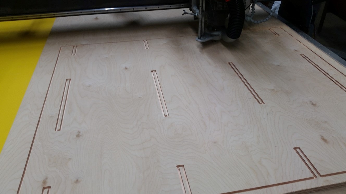
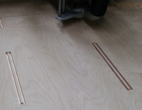
Update: I was asked during the review how I was able get a clean top surface with an up-cut spiral bit. My answer was feeds and speeds. So I've decided to include a less compressed image showing the surface during the cut.
Week 8
Embedded Programming
My instructor Wendy Neale suggested I use Emma Pareschi, Ted Hung, and HighLowTech
for guidance for the following week. I also used David Mason for guidance.ATMEL Specs Document and data sheet LINK
ATTINY PACKAGE LINK
FABISP Drivers LINK
Installing the USB tiny drivers on a 64 bit windows system later than windows 7 can be difficult as driver signature checking can be difficult to turn off.
AVR MKII Windows Drivers LINK
My starting point was to download and install the Arduino IDE. The following step was to install the packages for the ATTINY44 in the Arduino platform (shown in the HighLowTech Tutorial).
I went into preferences and added "https://raw.githubusercontent.com/damellis/attiny/ide-1.6.x-boards-manager/package_damellis_attiny_index.json" to the board manager and downloaded the attiny package.
I set my board in Arduino IDE to the ATTINY44A and my clock to 20Mhz External.
Make sure to set the programmer to the appropriate piece of hardware you'll be using.
From this point on, assuming your hardware is sound and arent missing drivers or chip packages everything should be just as simple pushing some commands to your "Arduino".
Data Sheet
The Data Sheet for the ATTiny44A can be found here
Update: More Information I gleamed from the Data Sheet Can be found in Week11
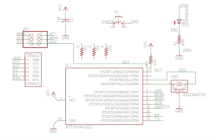
Referencing my original EAGLE Sketch, I learned the Physical Pin numbers for my Switch(10) and LED(6)
These pin numbers are important because we will have to convert them to their internal pin numbers, from what I understand this has to do with the internal wiring of the transistor we are using. We must find the Pin numbers we will be using in Arduino IDE
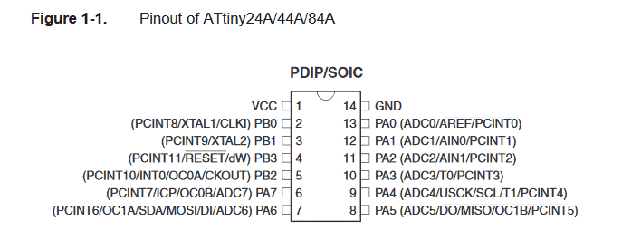
I learned that Pin 6(LED) shown in Figure 1-1 is actually Pin 7, and Pin 10(SWITCH) is actually Pin 3.
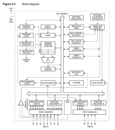
I'd like at some point in the future to try to use simple transistors and electrical components to build a larger scale IC so as to learn the internal specifics of these chips. I found an image in the DATASHEET showing some of the logic flow.
Let's start trying to program our board.
set Pin 7 to HIGH.
Yeah of course it isn't that easy. I'm getting errors from Arduino IDE lots of them.
MISO Fail, MOSI Fail, SCK Fail.
Time to trouble shoot.
I attempted to use my ISP to program my board using a couple of different references. I had almost no luck in getting them to work. My report from the AVR in Arduino IDE was RST and MOSI error. After examining my board I had some heat damage underneath my 6 pin.
After closer inspection I don't believe my board can be repaired. I'll be rebuilding my board shortly.
REBUILD
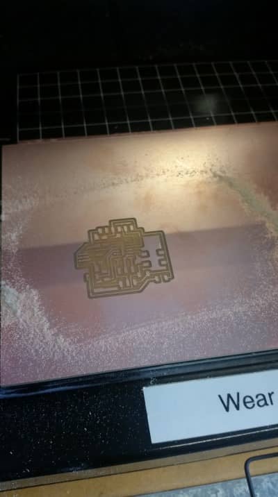
I was let onto another way to home the Z axis of the Modela. I was originally taught to bring the bit down till it was just on the surface of the Cutting material, then run the job.
The CORRECT way I learned is to bring the bit to just above the surface of the PCB, Loosen the chuck of the Mill and drop the bit onto the surface of the PCB and tighten the chuck again.
Using the Move command it is now possible to check if the PCB is level to the cutting head.
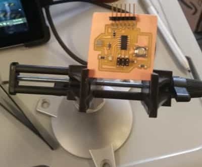
I reorganized my board layout removing a 0 ohm resistor and optimizing a couple traces. Time to occupy the board with components.
I noticed part of my 6 pin had no trace on connecting it anywhere. After examining my Schematic I learned one of my nets was not named properly. I added the RST trace into my schematic and have begun building my board again for the 4th time.
REBUILD
Updated Board Schematic and layout
Still Having little success, I replaced only the tiny 44 chip this time. I am able to blink!
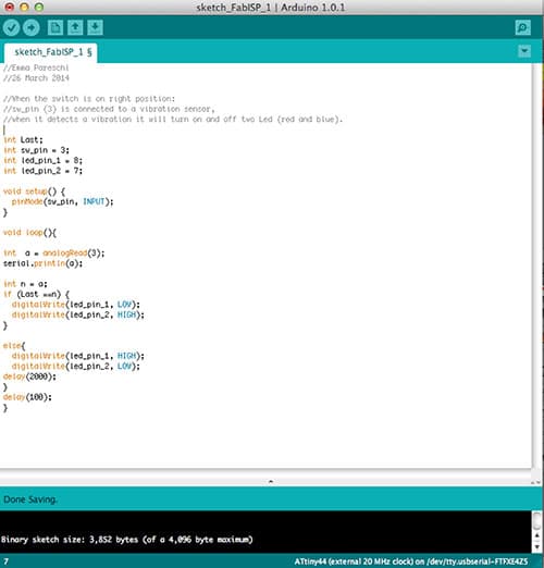
I wrote a small chunk of code to test the function of my board. I used portions of code from the different example scripts that come with Arduino IDE. I learned I am much better at reading Arduino C than I am speaking it.
/*
Steven Fett 2016 Fab Academy
Week 8 Embedded Programming
5th Revision to Physical Board
2nd Revision to this program
*/
// we will define our pins
const int ledPin = 7; //This is the outut pin for our led, this is pin 6 in the schematic
const int buttonPin = 3; // This is the Input pin for our button, this is pin 10 in the schematic
int buttonState = 0;
void setup() {
//we will set our conatants to do stuff here
pinMode (buttonPin, INPUT);
pinMode (ledPin, OUTPUT);
}
void loop() {
//we ask the tiny to listen for action on pin 3
buttonState = digitalRead(buttonPin);
// in this following statement we ask if the button status is high
if (buttonState == LOW) {
//we tell the tiny44 to turn on our led
digitalWrite(ledPin, HIGH);
//we then wait while the led is on
delay(3);
//we turn off the led
digitalWrite(ledPin, LOW);
// we wait a bit longer while the diode is off
delay(30);
// this gives us a mostly off blink
} else {
//when the button is pressed the diode will illuminate
digitalWrite(ledPin, HIGH);
// we add a small delay so we can see the effect of the diode being illuminated
delay(30);
// rinse wash repeat
}
}
After watching the behavior of my board I'm thinking my data flow in my code is incorrect. I will need to switch buttonState functions. IE commands under buttonState LOW and else need to be switch and buttonState LOW needs to become buttonState HIGH.
/*
Steven Fett 2016 Fab Academy
Week 8 Embedded Programming
5th Revision to Physical Board
3rd Revision to this program
*/
// we will define our pins
const int ledPin = 7; //This is the outut pin for our led, this is pin 6 in the schematic
const int buttonPin = 3; // This is the Input pin for our button, this is pin 10 in the schematic
int buttonState = 0;
void setup() {
//we will set our conatants to do stuff here
pinMode (buttonPin, INPUT);
pinMode (ledPin, OUTPUT);
}
void loop() {
//we ask the tiny to listen for action on pin 3
buttonState = digitalRead(buttonPin);
// in this following statement we ask if the button status is high
if (buttonState == HIGH) {
//we tell the tiny44 to turn on our led
digitalWrite(ledPin, HIGH);
//we then wait while the led is on
delay(3);
//we turn off the led
digitalWrite(ledPin, LOW);
// we wait a bit longer while the diode is off
delay(30);
// this gives us a mostly off blink
} else {
//when the button is pressed the diode will illuminate
digitalWrite(ledPin, HIGH);
// we add a small delay so we can see the effect of the diode being illuminated
delay(300);
// rinse wash repeat
}
}
I've switched the function of my button to have the LED Blink untill the button is pressed then remain lit for a duration of time.