Fab Academy 2016
COMPUTER-CONTROLLED CUTTING
Design and make a corrugated cardboard press-fit construction kit
Project Files:
Tools Used:
What are we going to make?
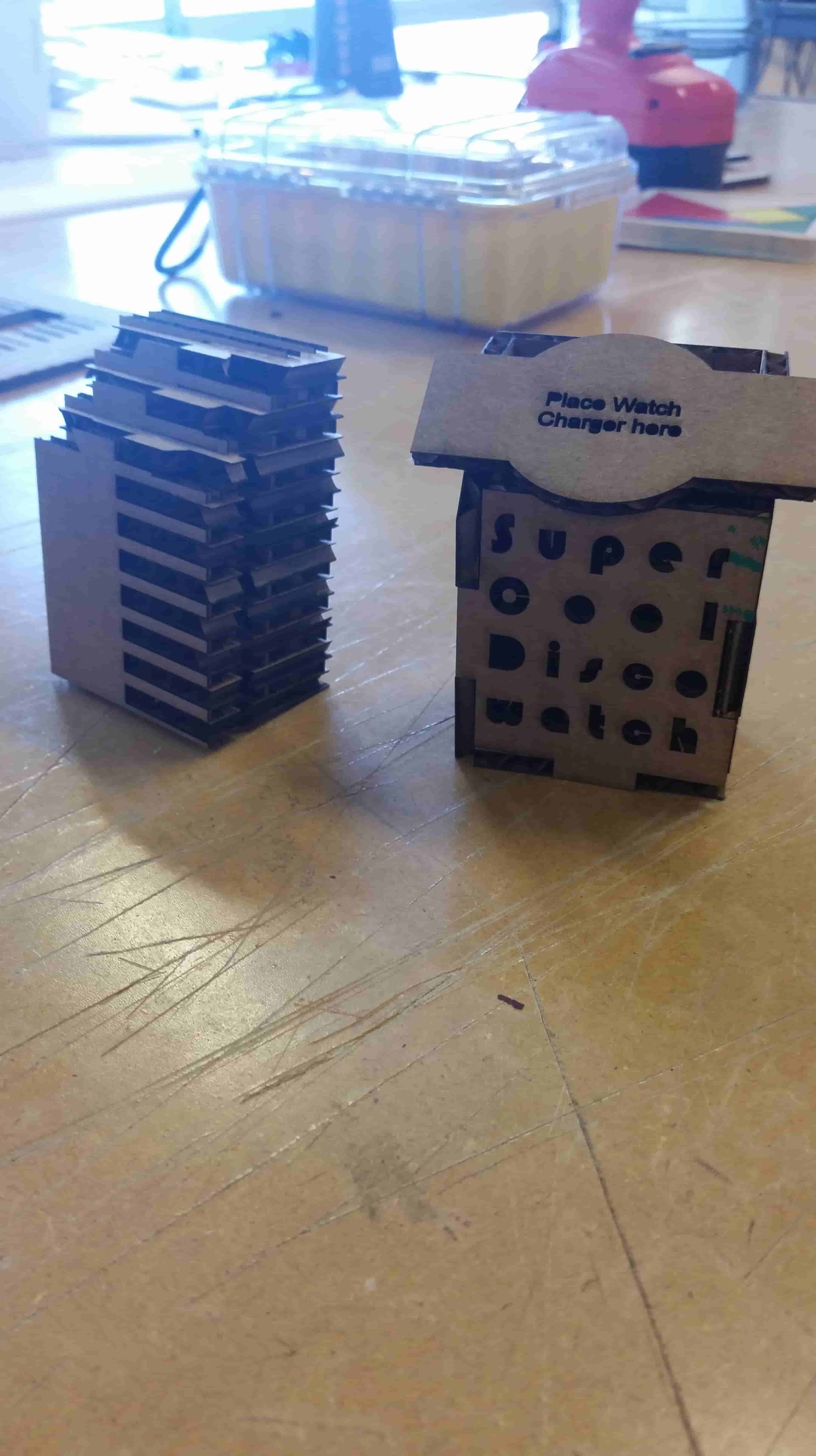
How about a stand for my smart watch. OK!
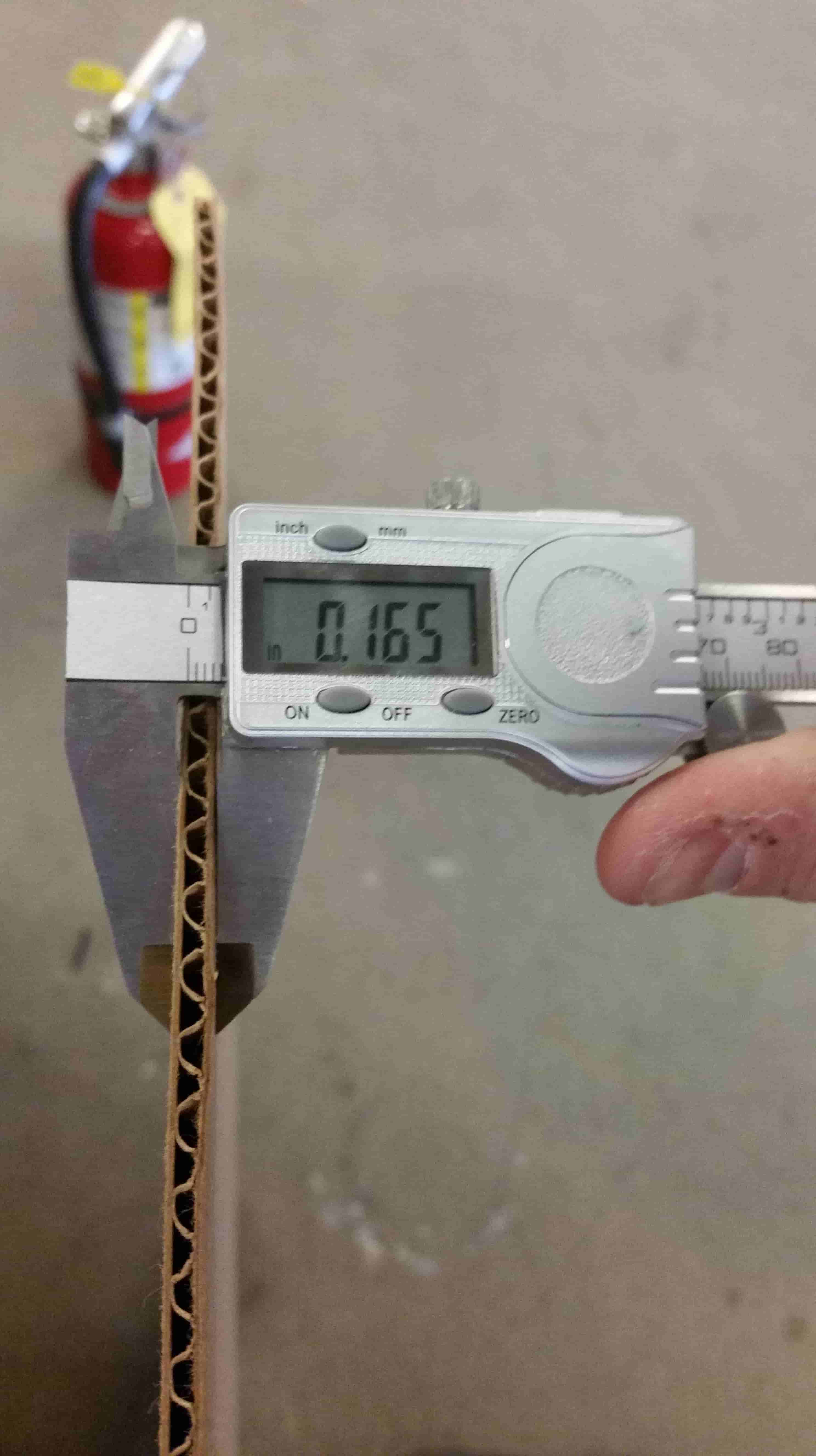
First step, figure out the actual thickness of the material.
Let's create a drawing of what we are working with.
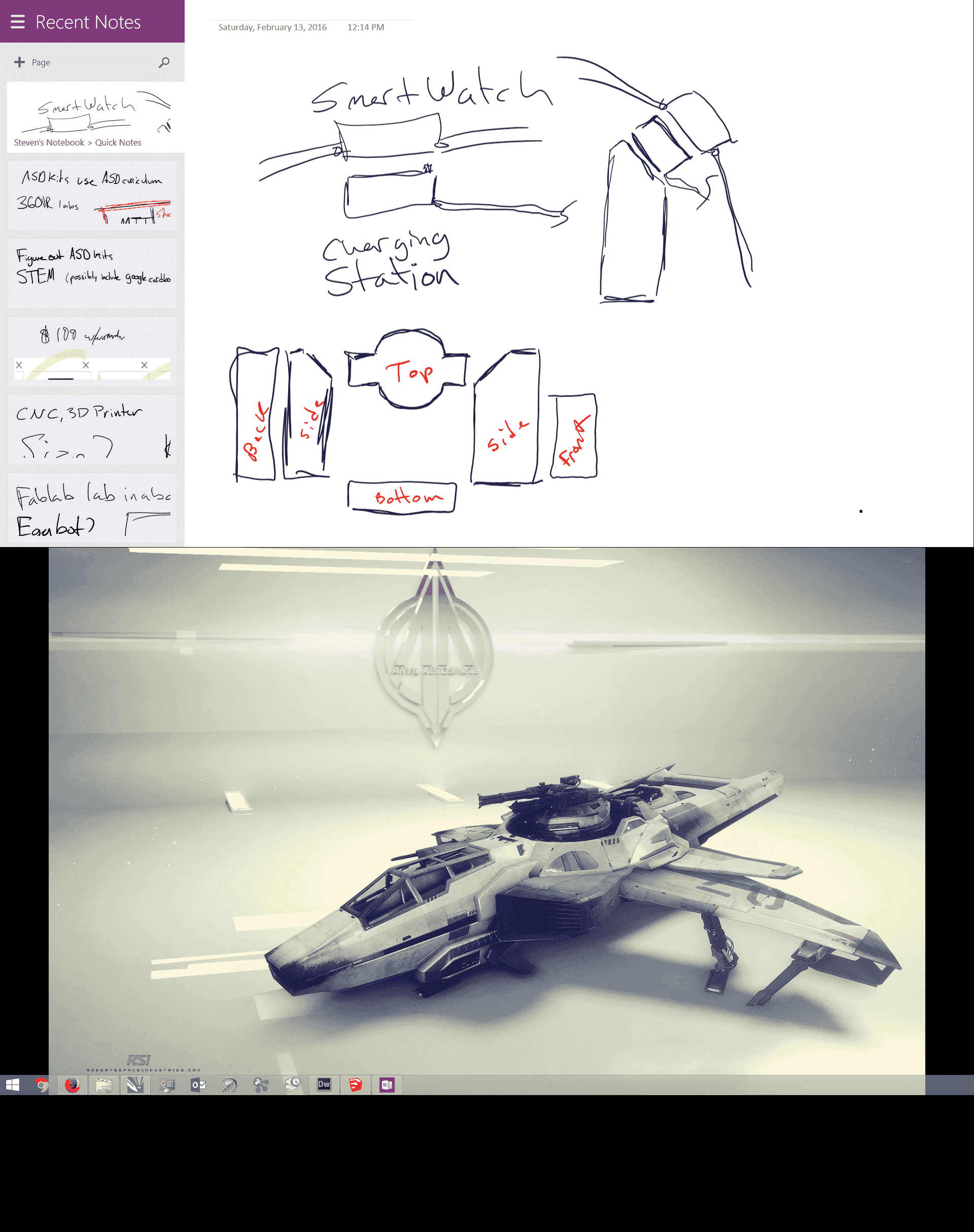
Lets drag over our sketch so we can use it as a reference

Double check our scale.
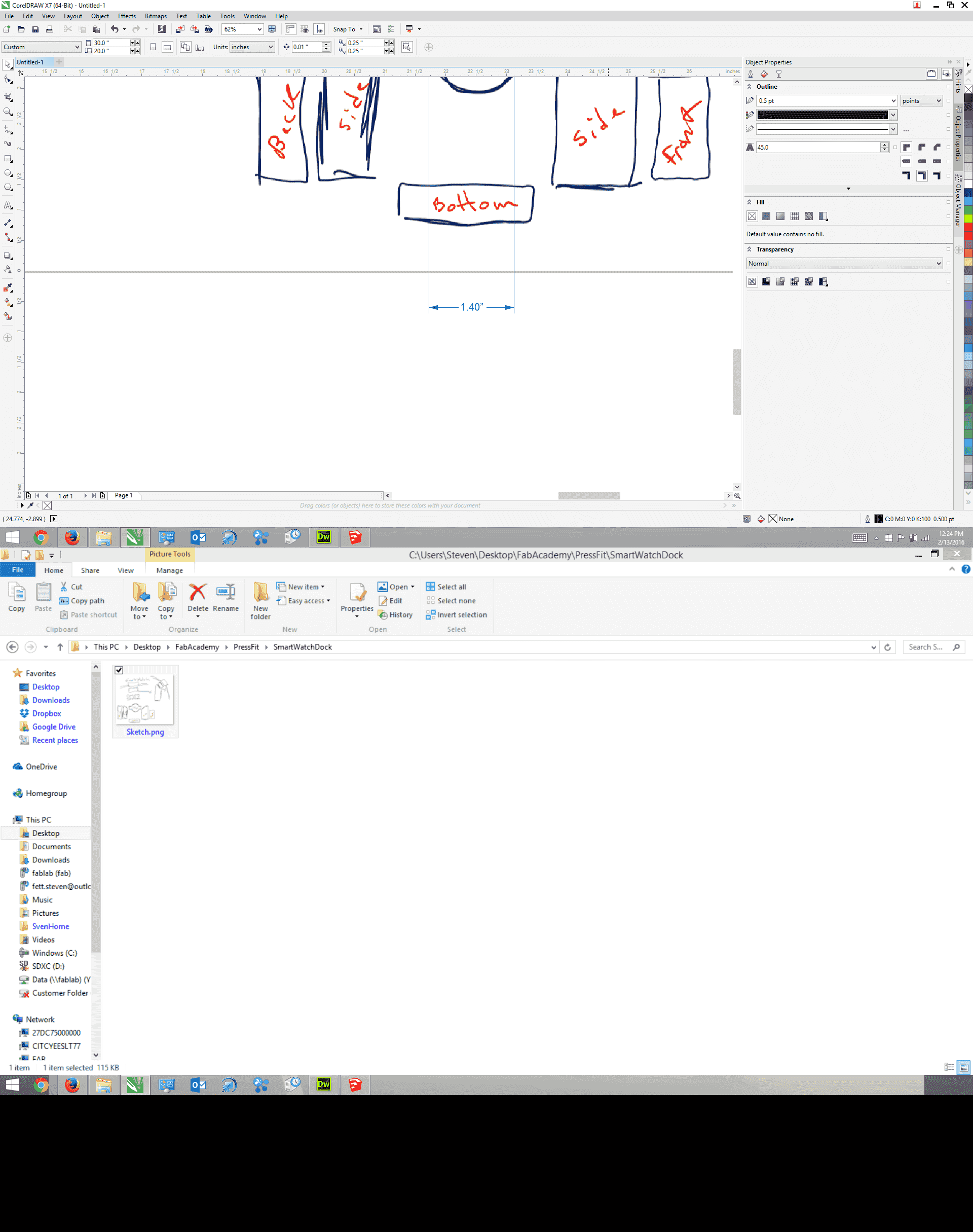
Use the merge tool at the top to create new shapes.
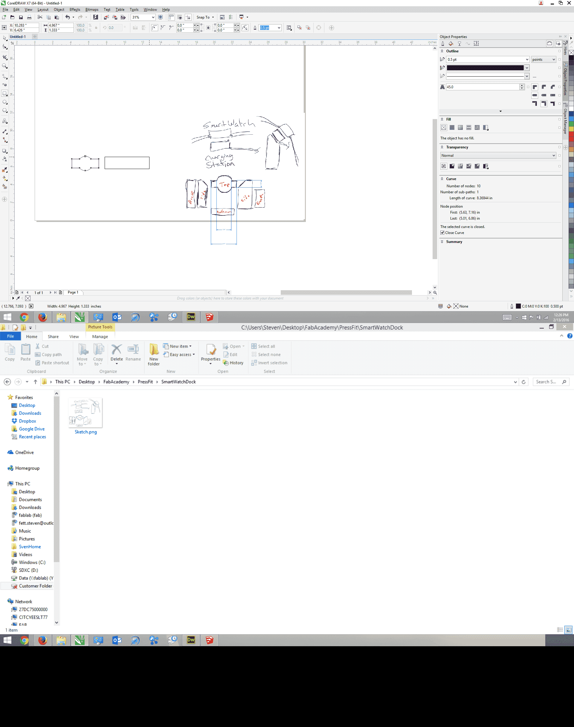
Awesome, this is one of the side walls. It will support our top at 45°
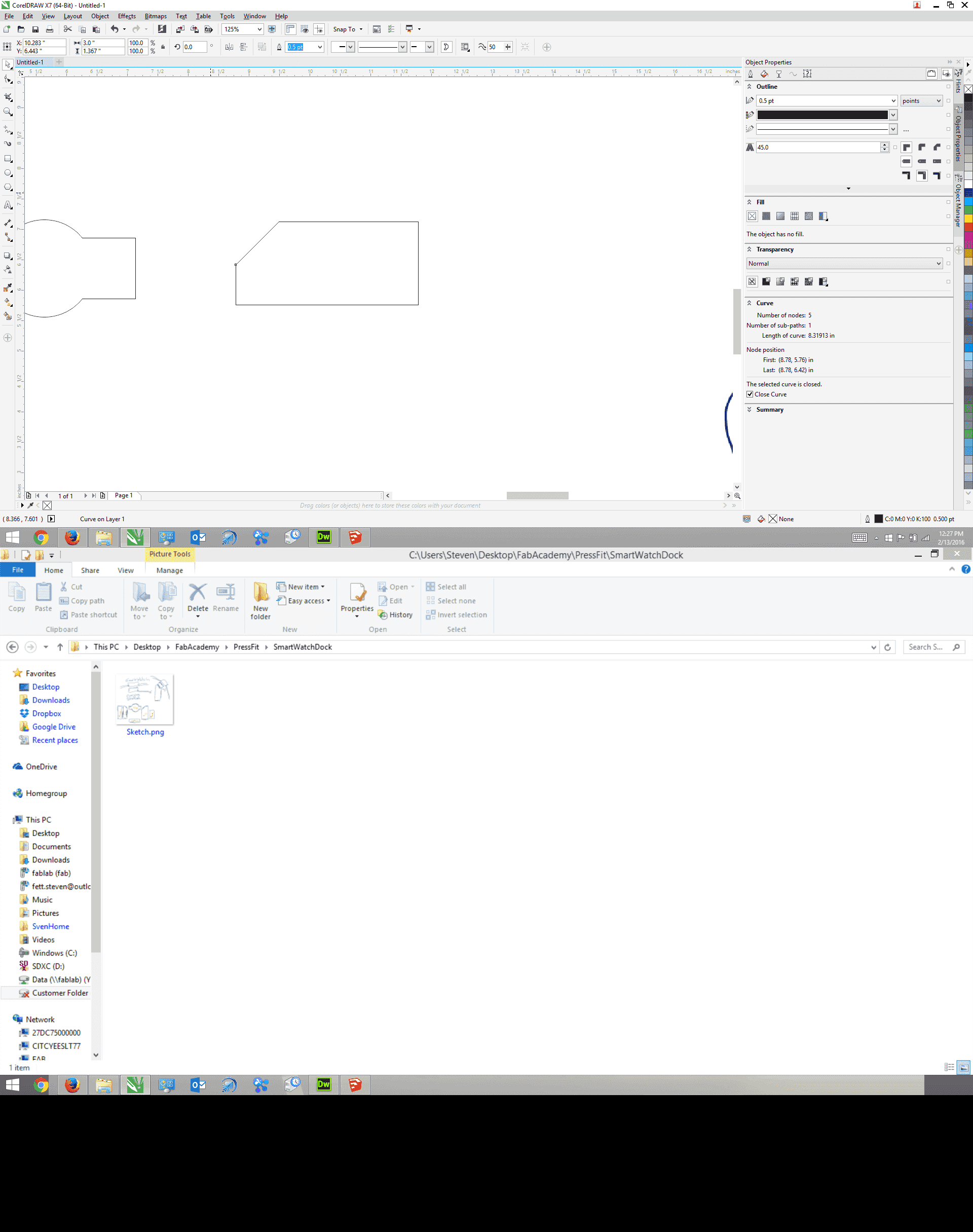
Fairly good looking reproduction.
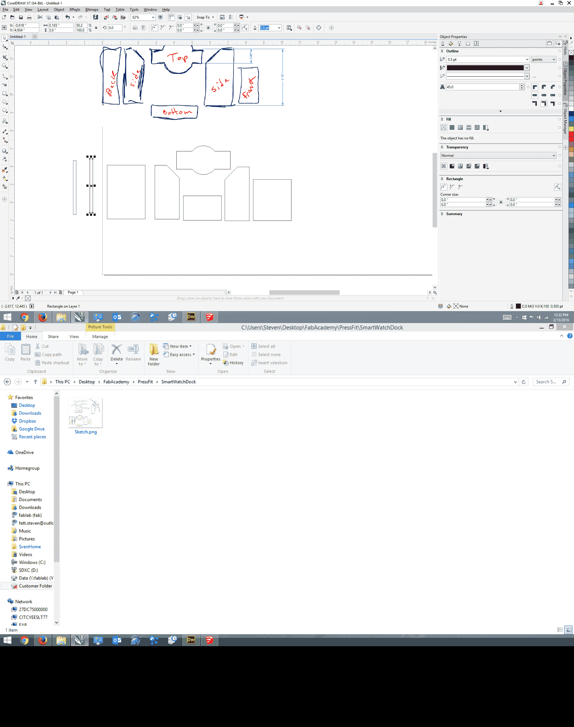
Let's start creating our notches that'll fit our cardboard together.
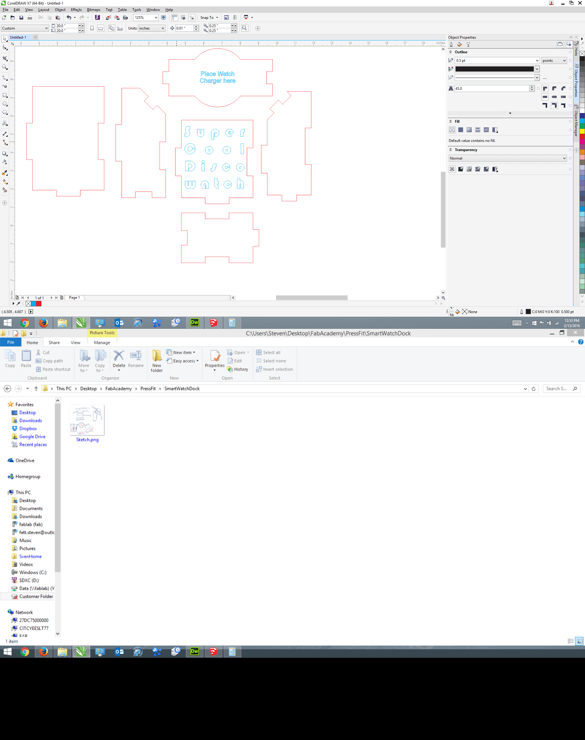
This'll fit.

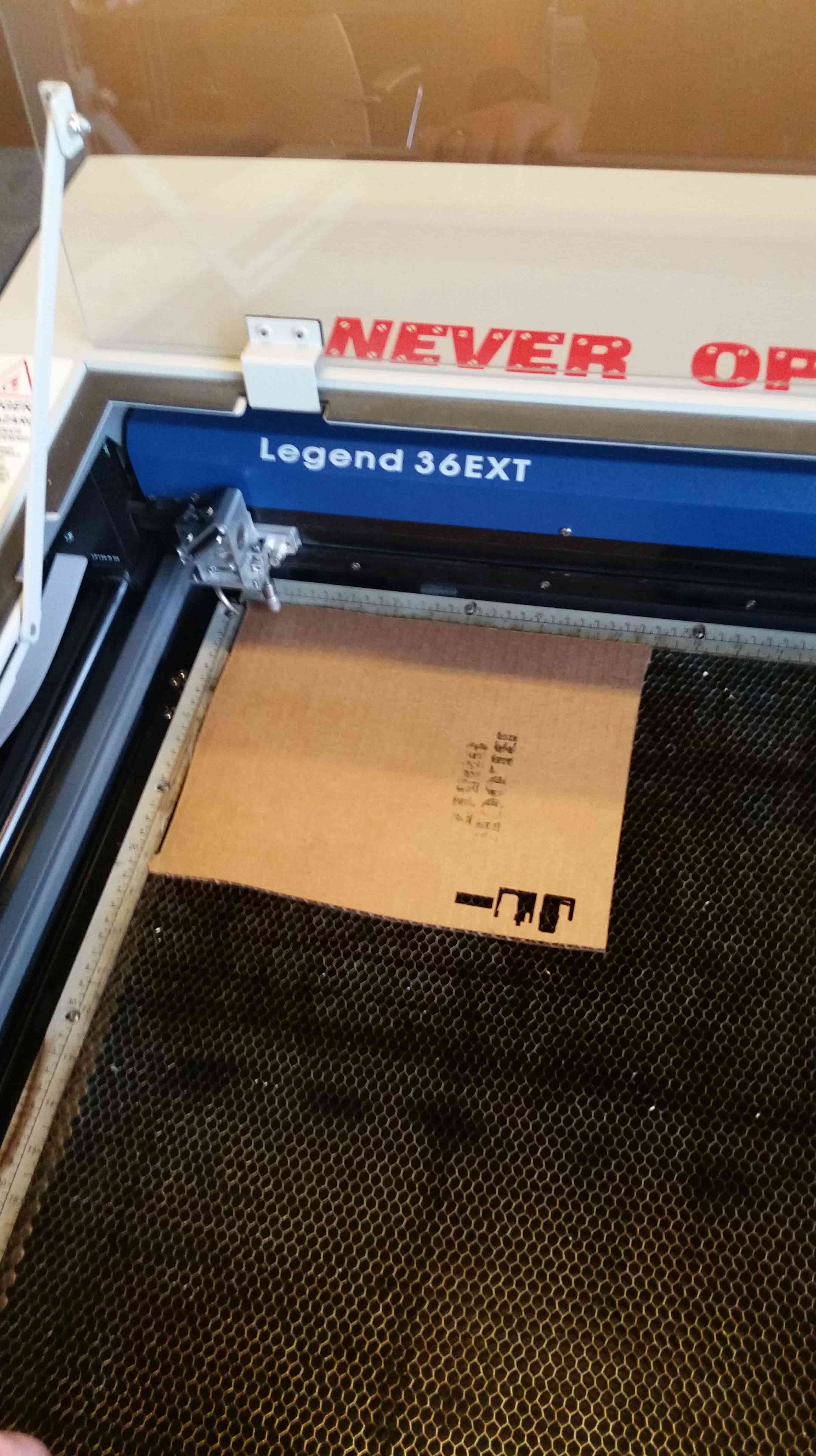
Turn the laser cutter on.

Square your material in the top left corner of the machine.
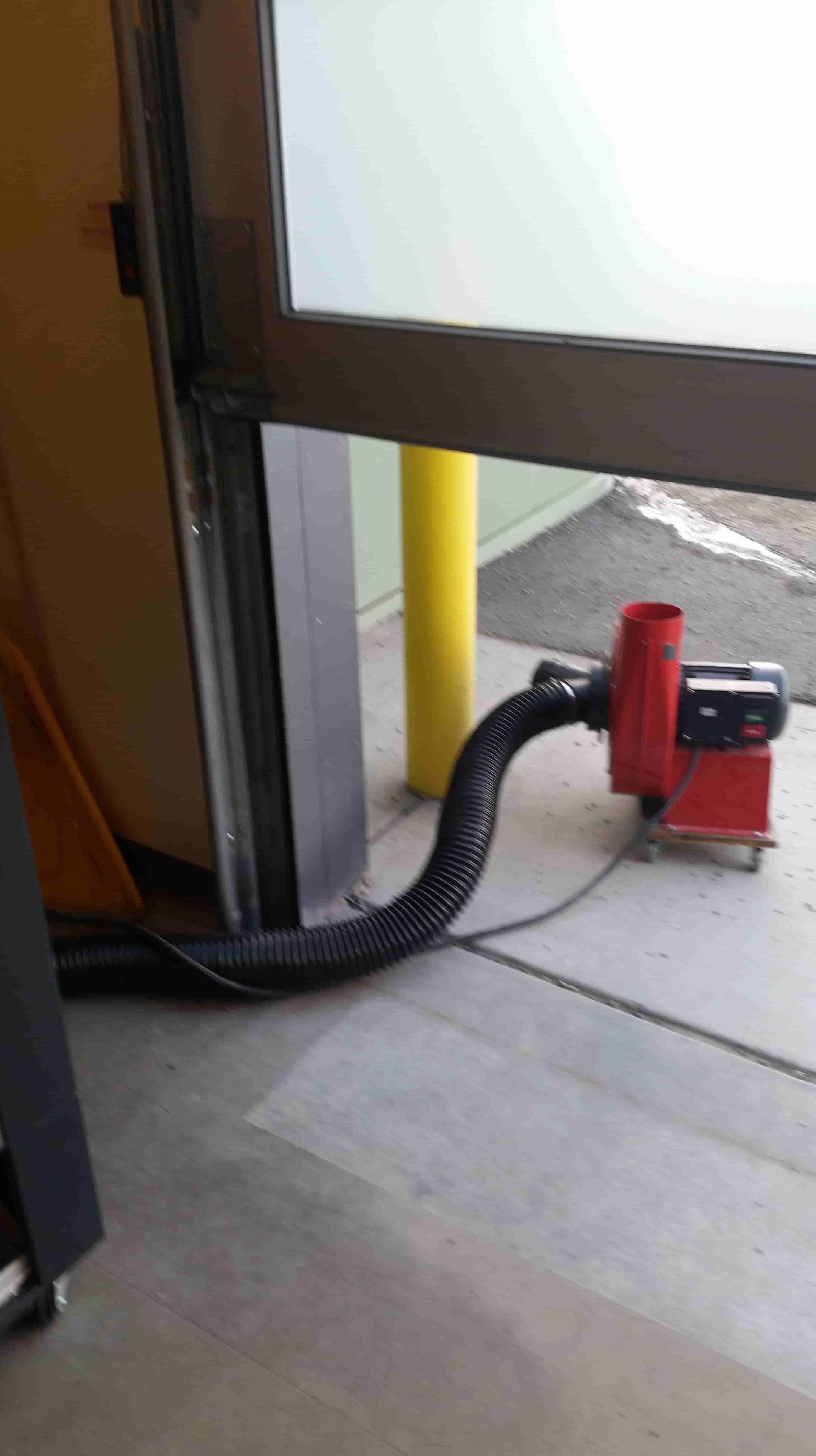
Open the garage door and escort the blower outside
Turn the blower on, and close the garage door, stop the door before it crushes the blower hose, PLEASE
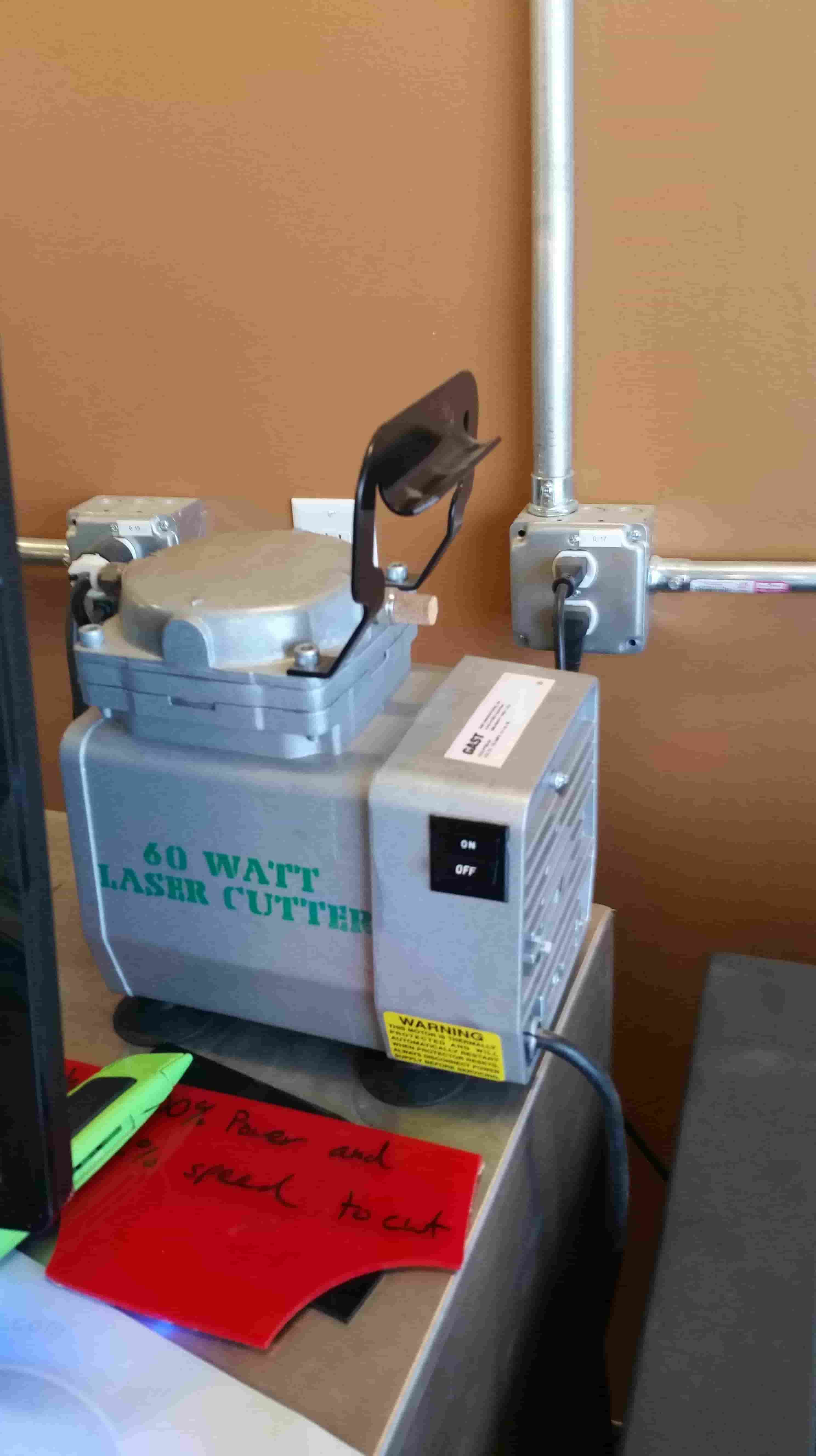
Turn on the air compressor
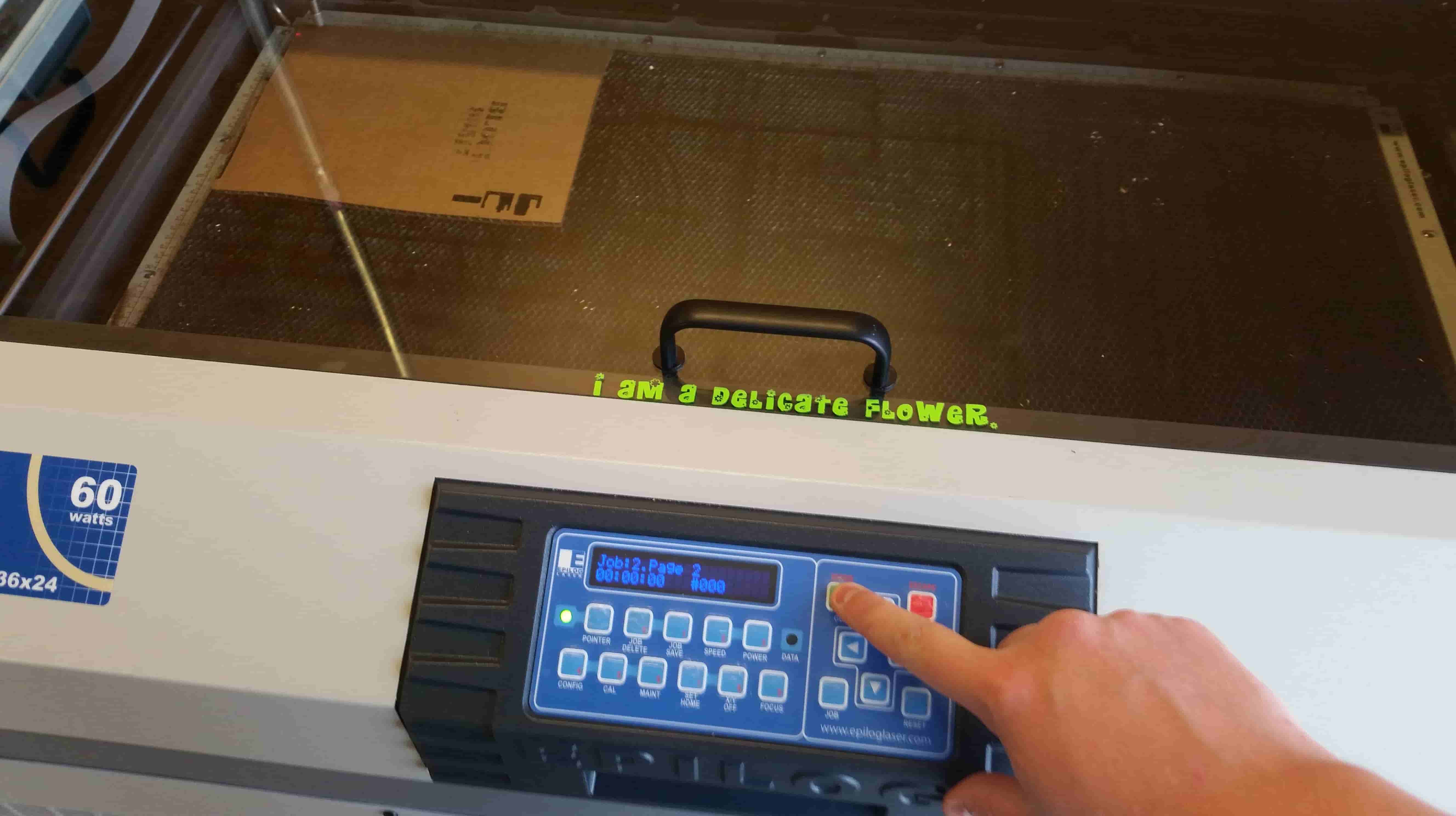
(see bottom for actual laser cutter operation)
Once we sent our job from the laser cutter press go.
Looks pretty good.
ADOBE ILLUSTRATOR
Load up your file and select the objects you wish to cut.
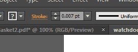
Be sure to adjust the line thickness
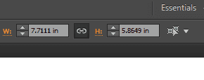
Verify the job size
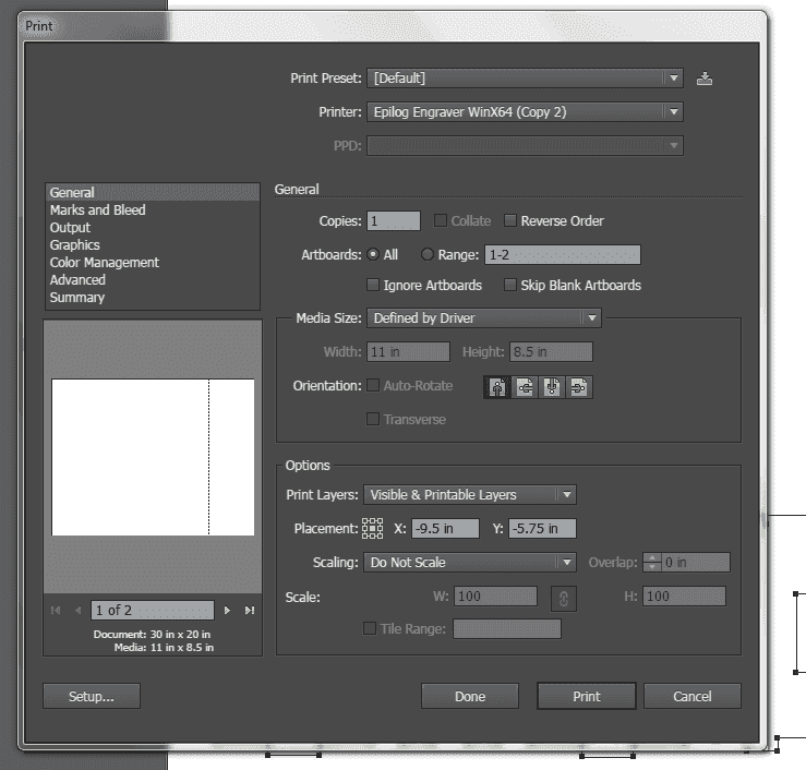
File > Print
Go to setup
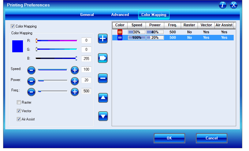
Let's head over and turn on color mapping.
We need to set our speeds and powers for each of our colored tool paths.
Once this is set press OK, then OK , then print the job. Press GO on the machine and you're done.
I've decided to try another type of press fit. and gave 123DMake a shot.
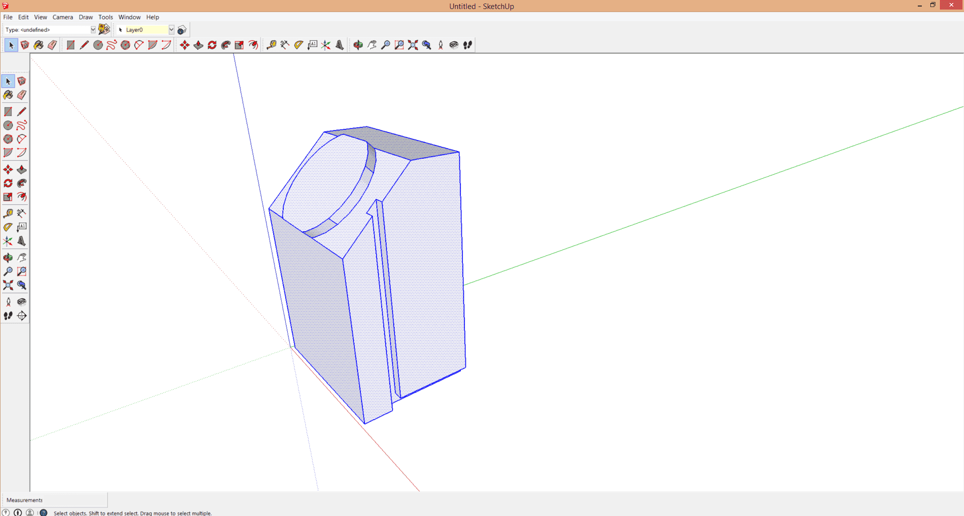
I jumped into Sketchup and drew up a 3D version of the first design.
Adding a channel down the side for the cable for the watch dock.
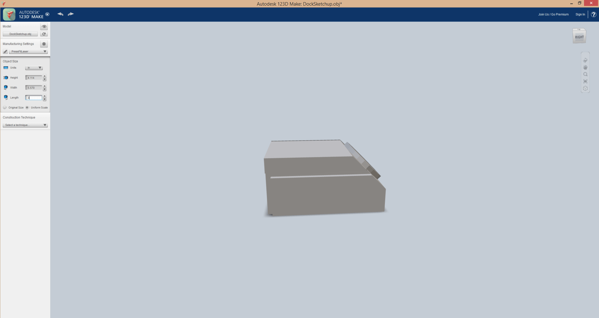
Exported to .obj and imported into 123DMake
Set up my material to 24"x36" .187" and ran interlocking for my job type.
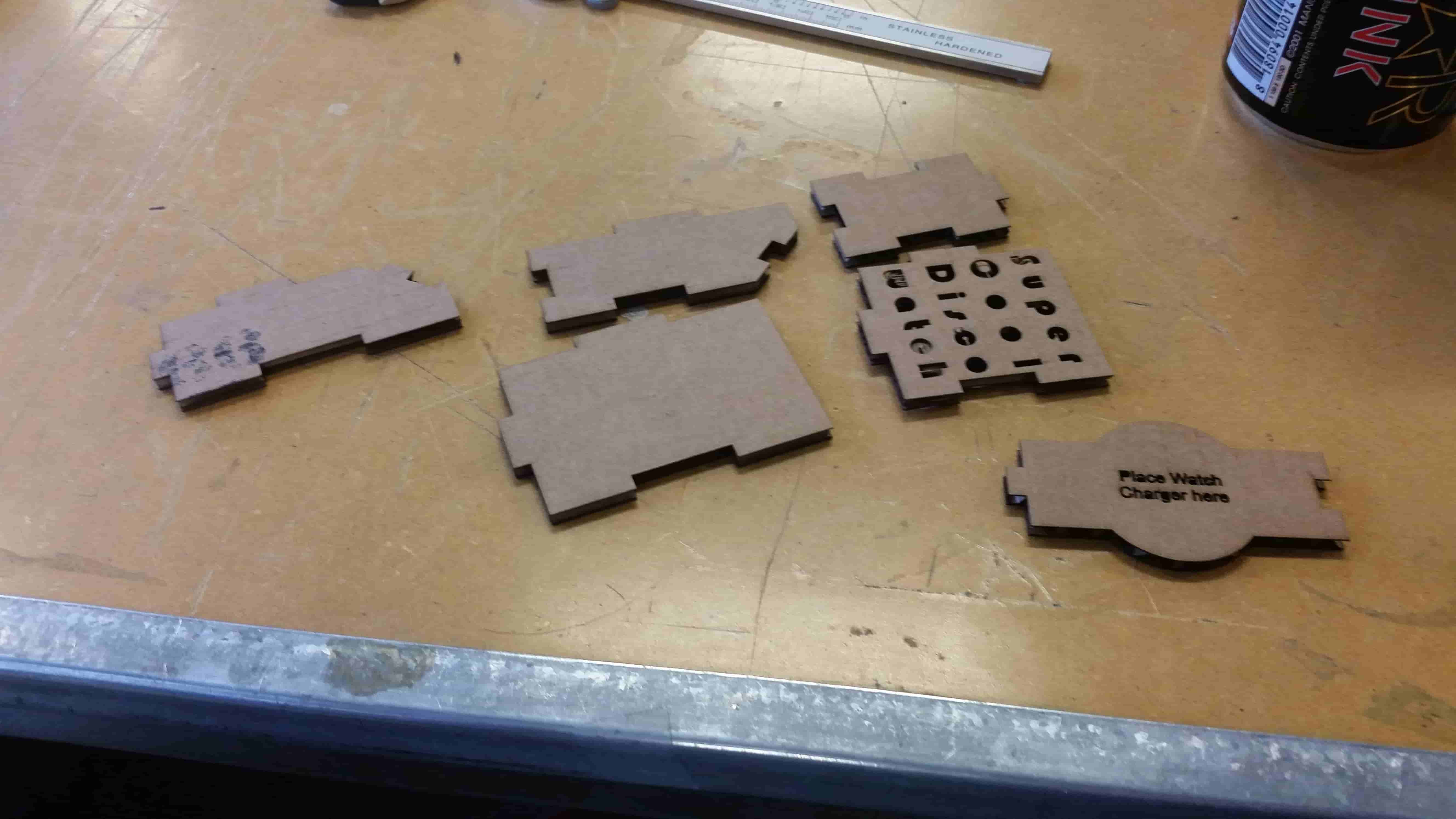
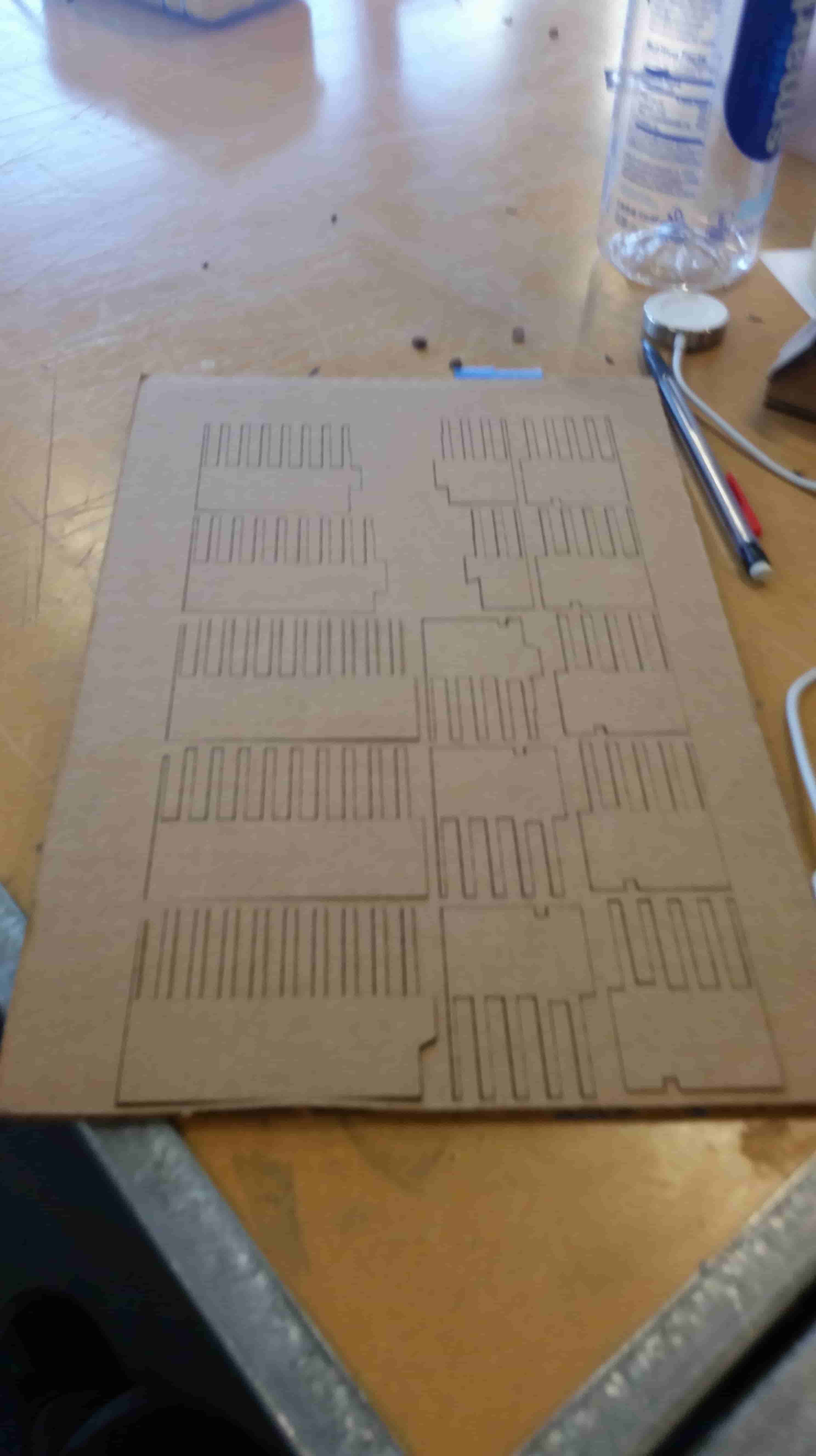
The parts all cut out.
Everything assembled
Update:Parametric
In an attempt to use more parametric software I've been attempting to us Fusion 360. The Sketching portion I feel like I've picked up fairly quickly however some of the software's higher functionality seems to be beyond my grasp. I think this has to do with my design habits. I believe I design myself into a corner where the Parametric Functions of Fusion 360 are no longer compatible. I'll need to visit more tutorials and get my parametric design habits up to snuff.
ELECTRONICS PRODUCTION
Make the Fab (tiny)ISP in-circuit programmer.
Tools:
Soldering Iron
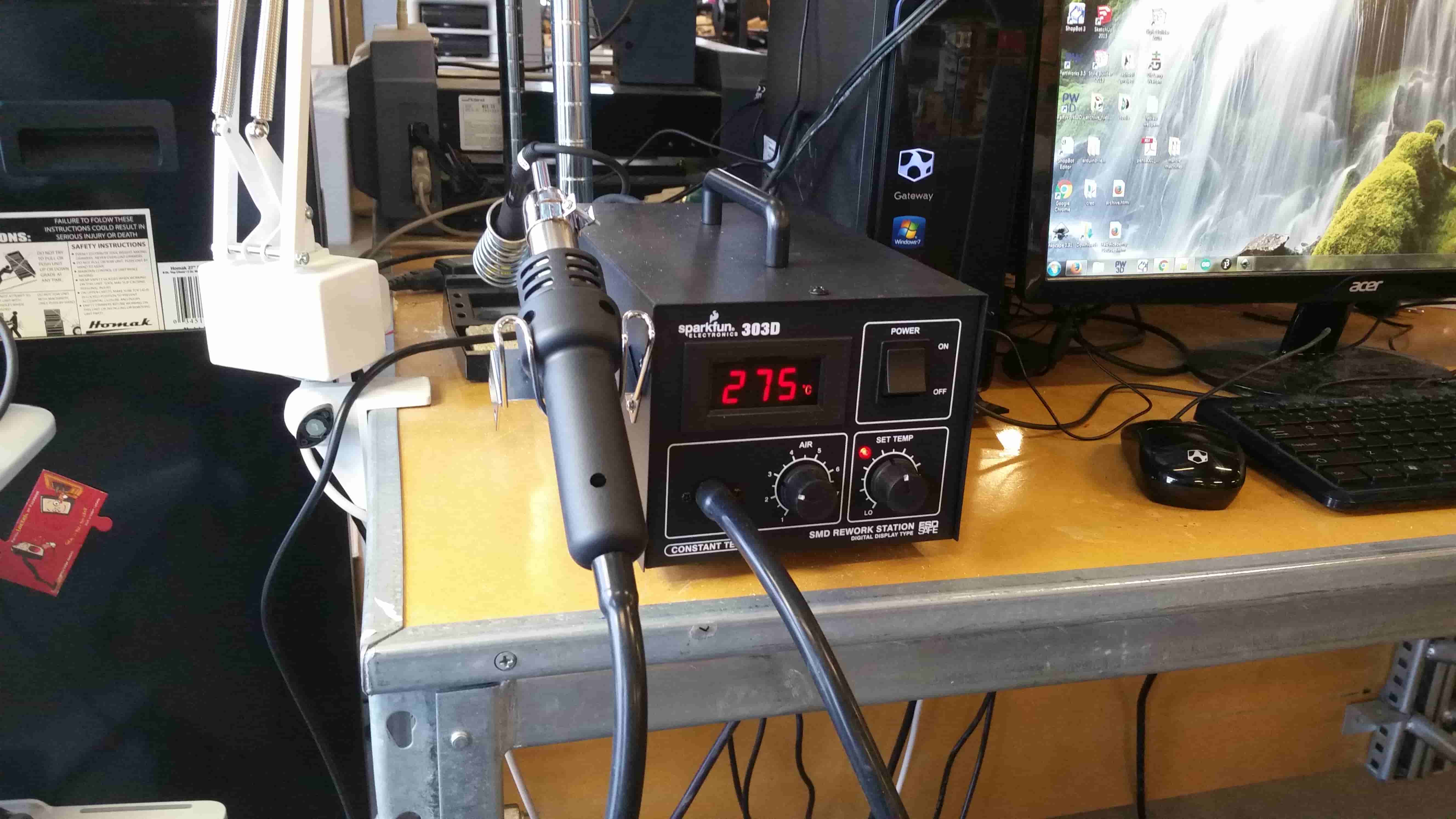
Re flow Hot Air Gun
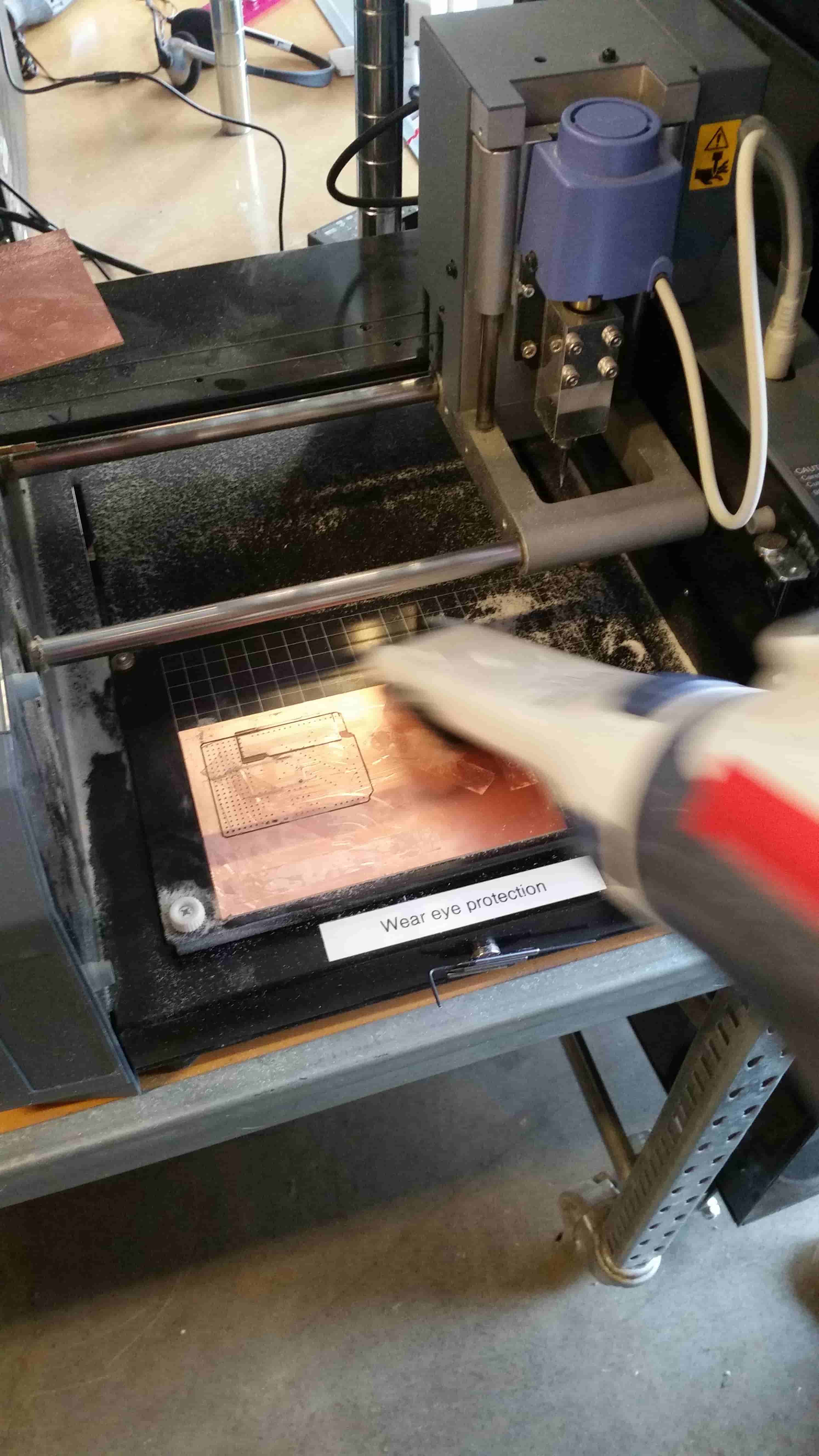
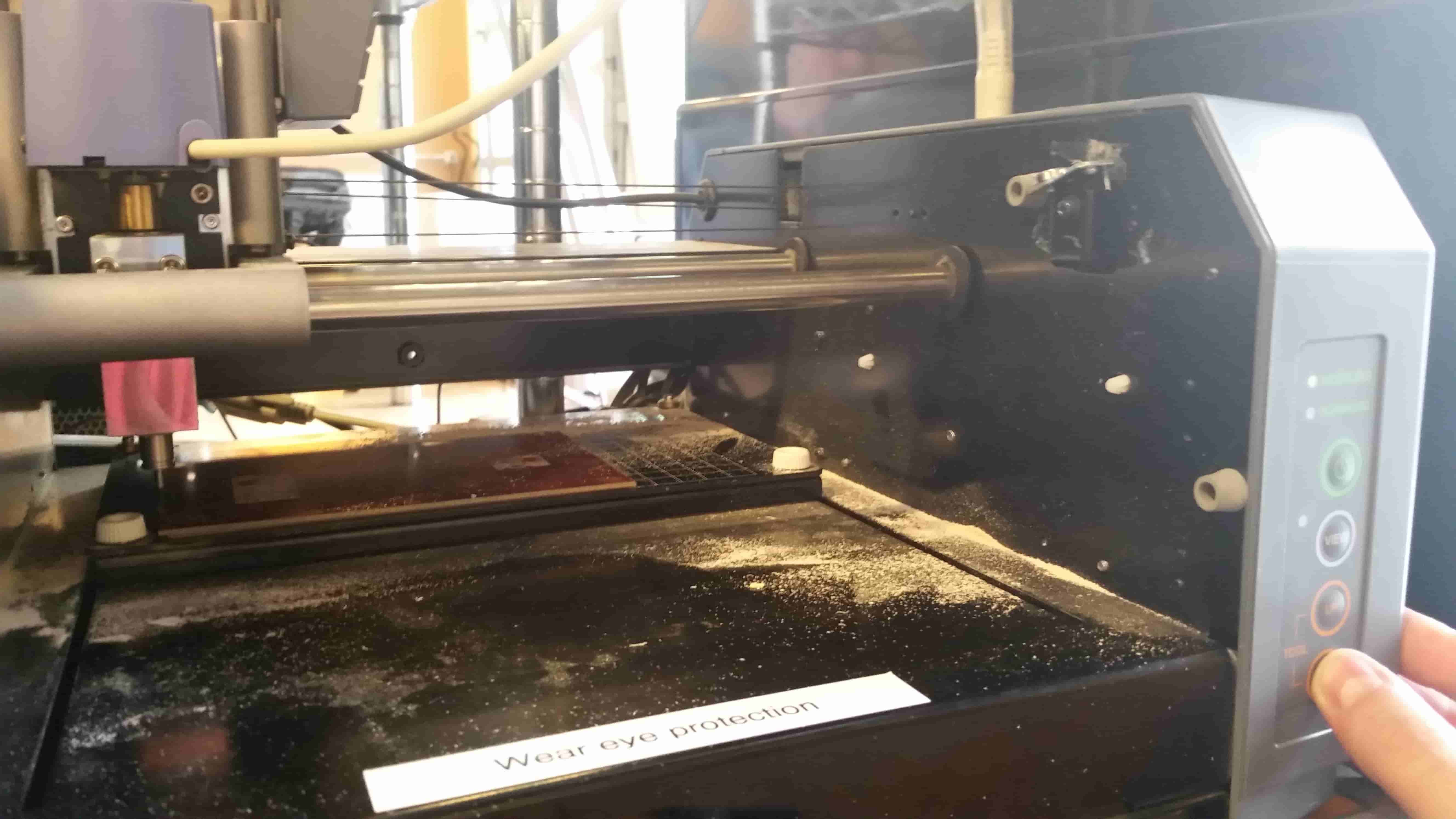
Roland Modela MDX-20
Linux Fab Module
Copper Boards
SMD Components:
1k Ω resistor
499 Ω resistor
2x 100 Ω resistor
10k Ω resistor
2x 3.3v resistor
2x 10pF Capacitor
1uF Capacitor
20 MHz Crystal
IC1 T44
6 pin interface
Let's clean up the mess first. Like Billy Corgan said "Cleanliness..."
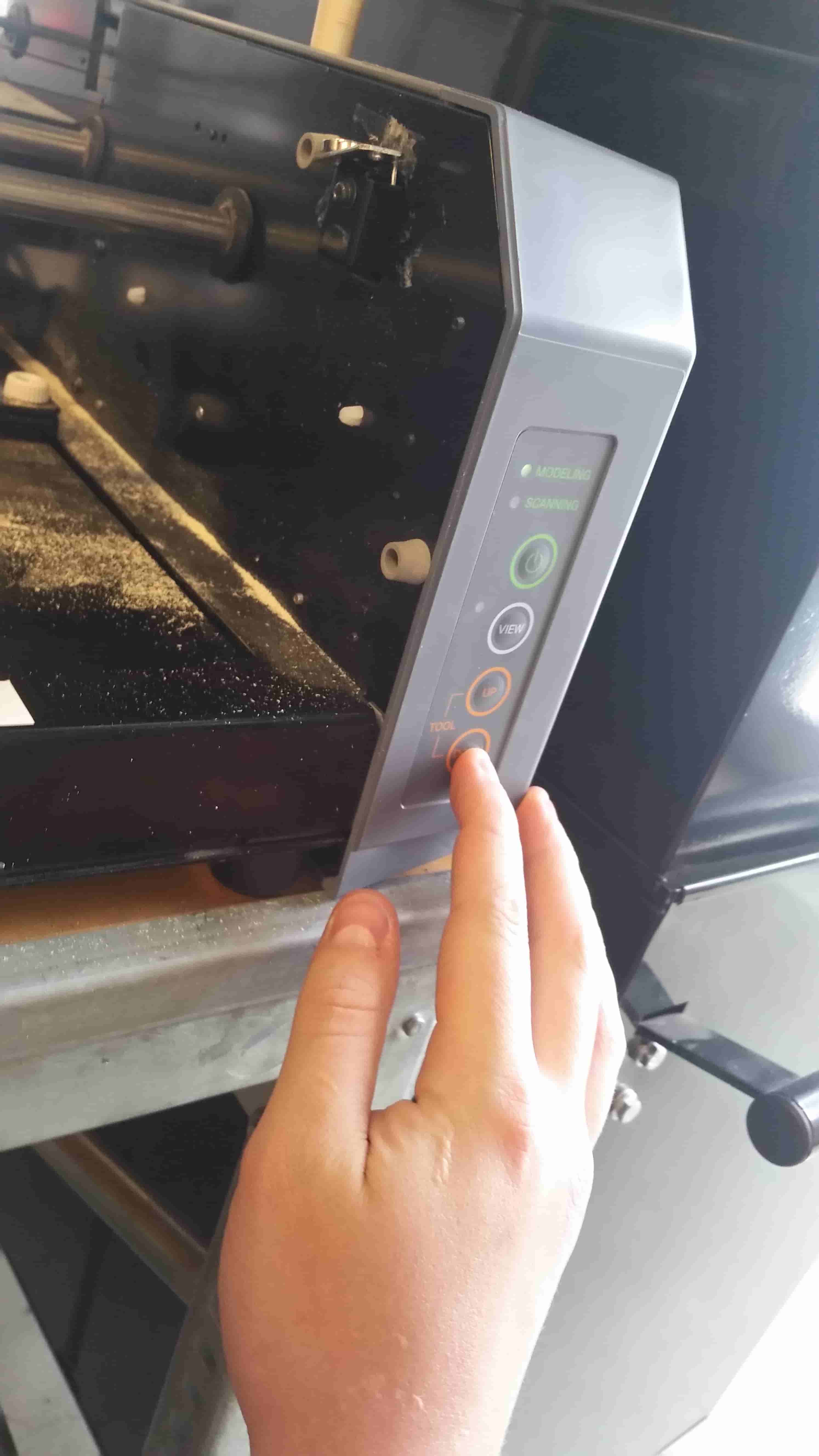
Clear out the memory by press up and down button at the same time
By far the best photo I've ever taken. I'll replace shortly
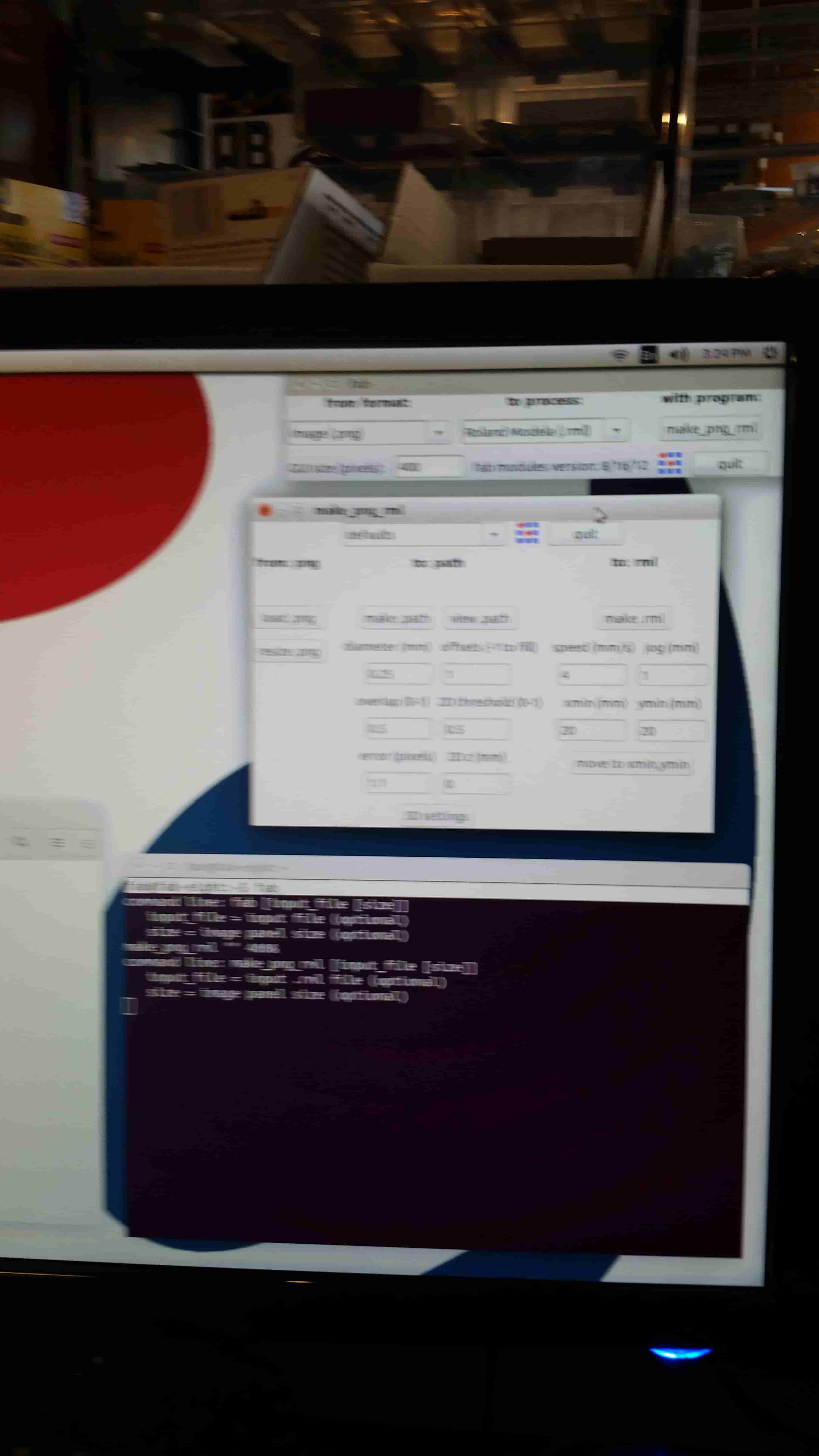
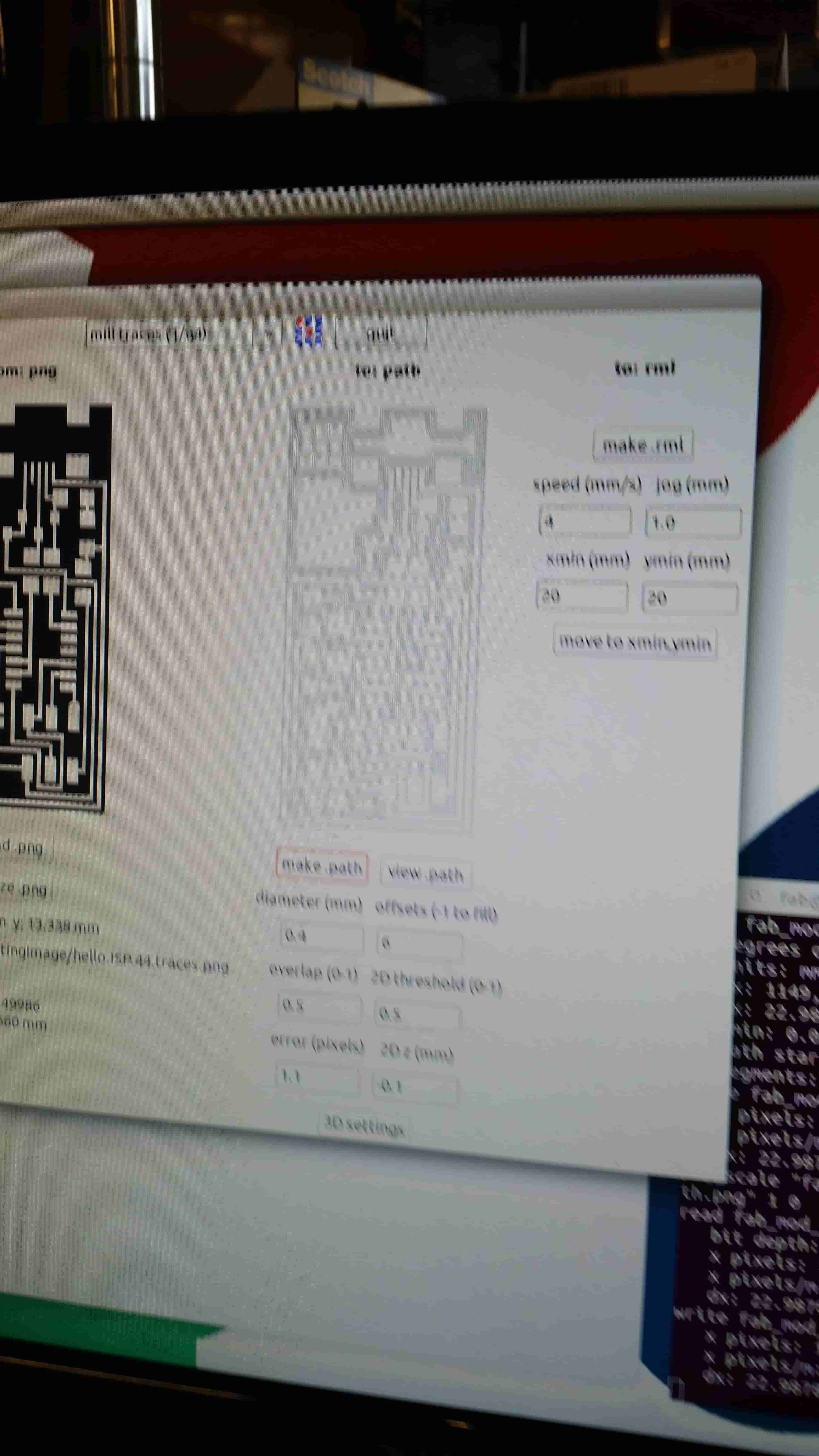
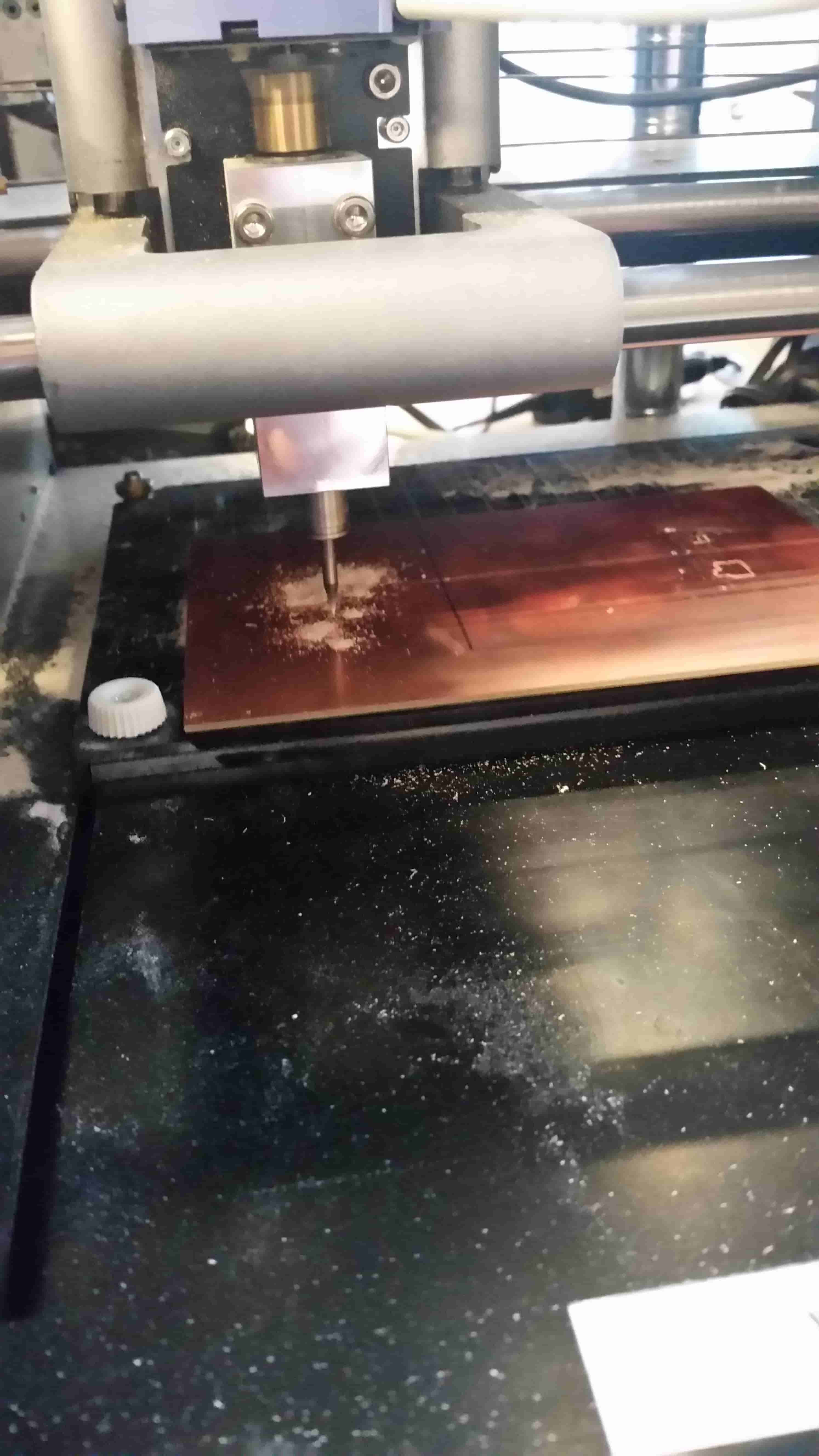
Load our cutting image, set the tool to 1/64th milling, check the parameters and make path.
let's double checked our path.
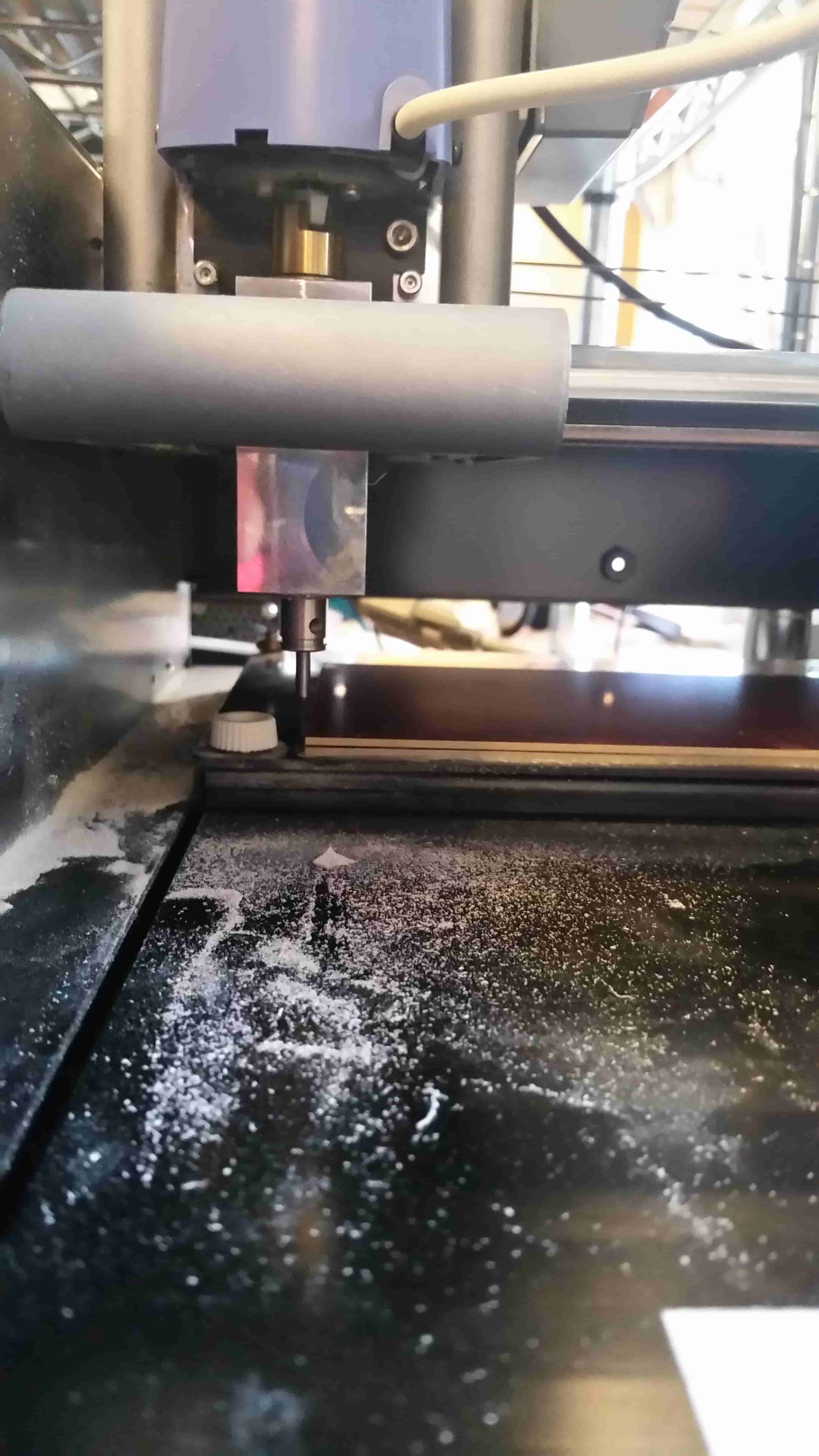
Now we must take the mill out of view mode and drop the tool head just onto the surface of the material. I typically stop once I've seen a tiny amount of chips on the board.
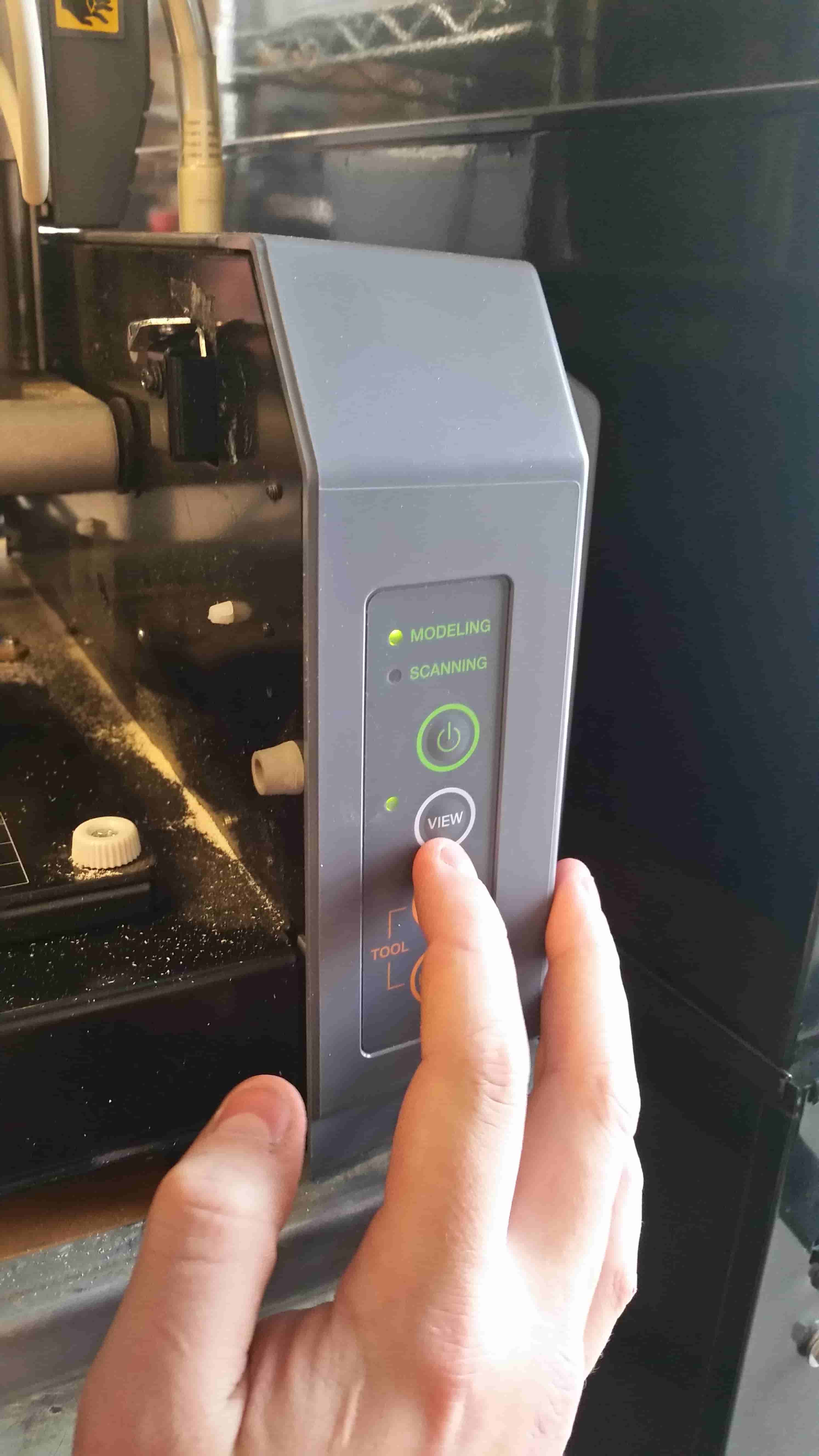
Walk it down real slow.
Yup. Right there.
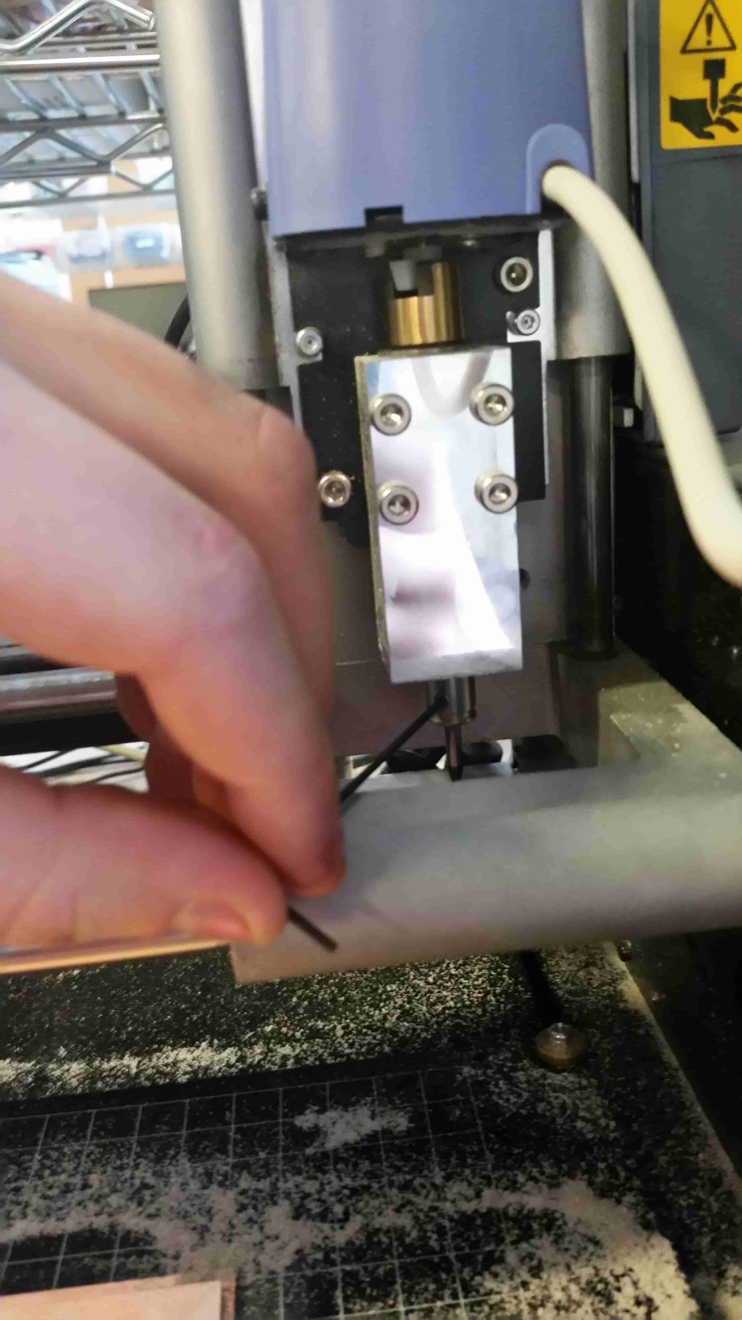
Update: Correct Z Zero
I was let onto another way to home the Z axis of the modela. I was originally thought to bring the bit down till it was just on the surface of the Cutting material, then run the job.
The CORRECT way I learned is to bring the bit to just above the surface of the PCB, Loosen the chuck of the Mill and drop the bit onto the surface of the PCB and tighten the chuck again.
Using the Move command it is now possible to check if the PCB is level to the cutting head.
If you press the send button on the computer, something like this happens.
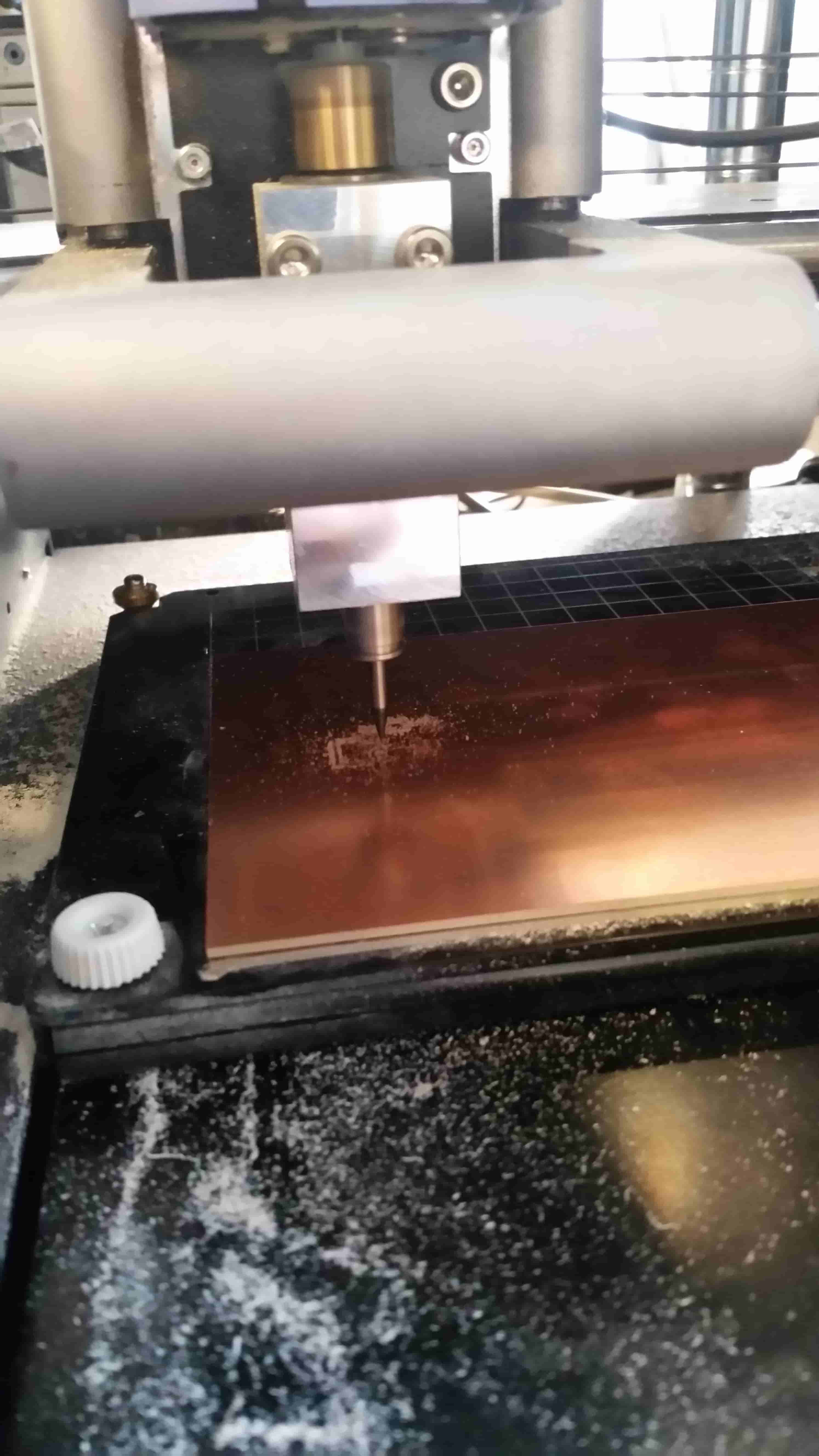
Looking good.
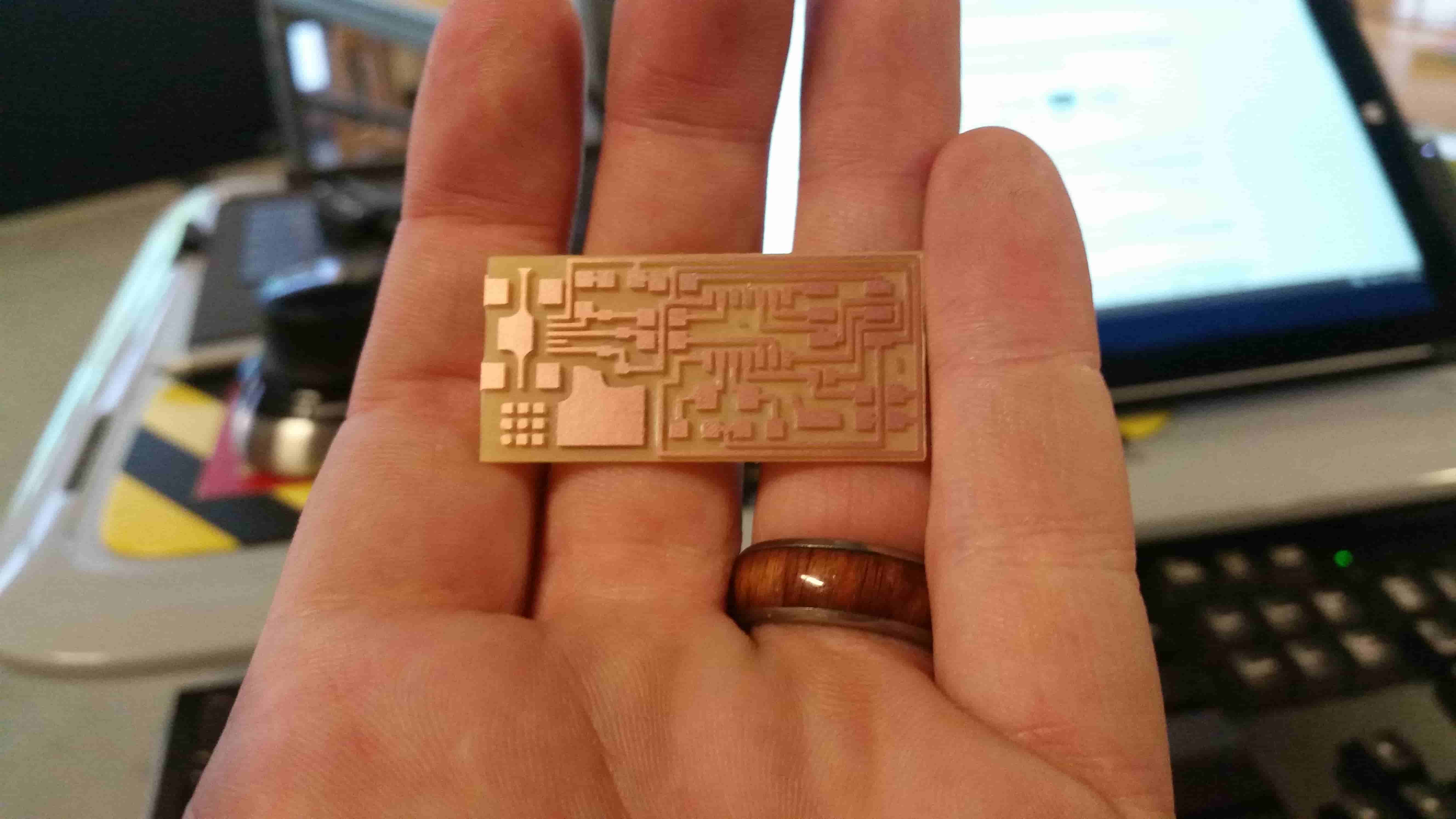
We've got to change our tool to the 1/32nd end to cut out our board.
Same Process as before, press up-down to clear the memory then take the mill out of view mode. Drop the tool head.
Wowwweee look at it go
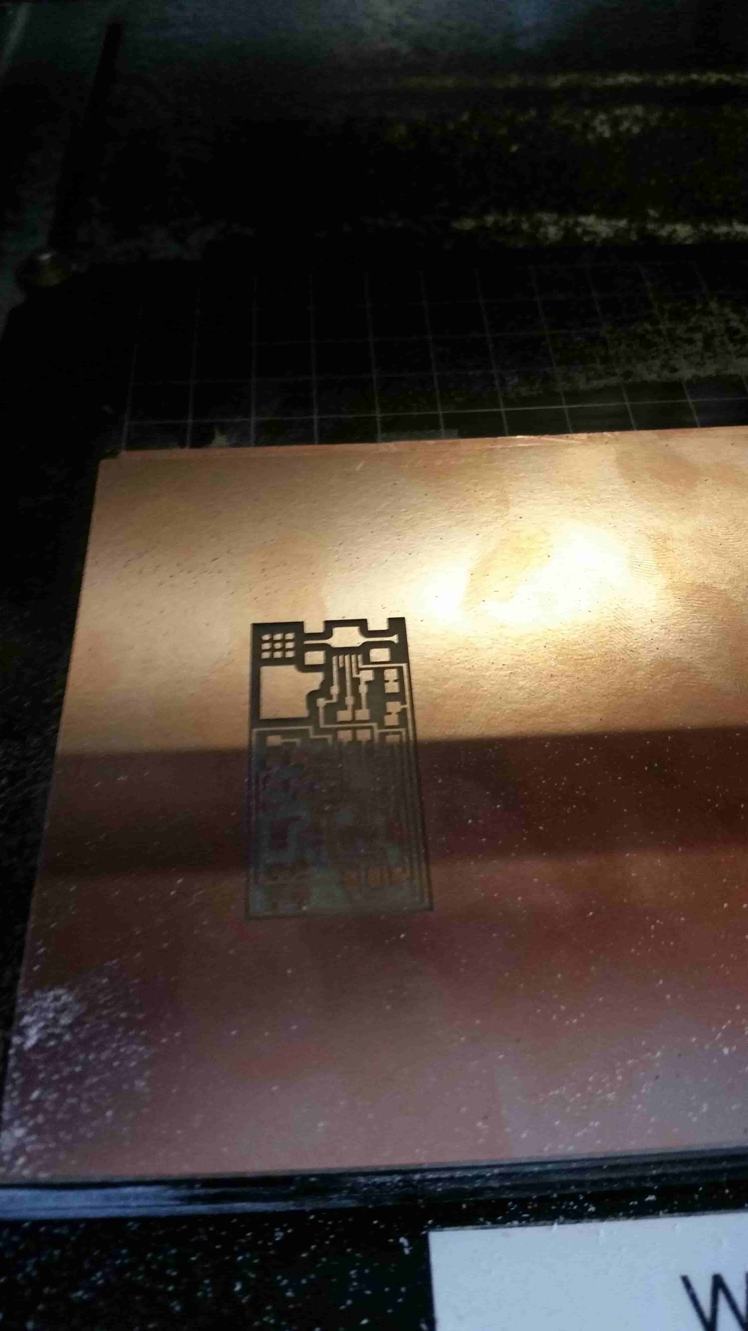
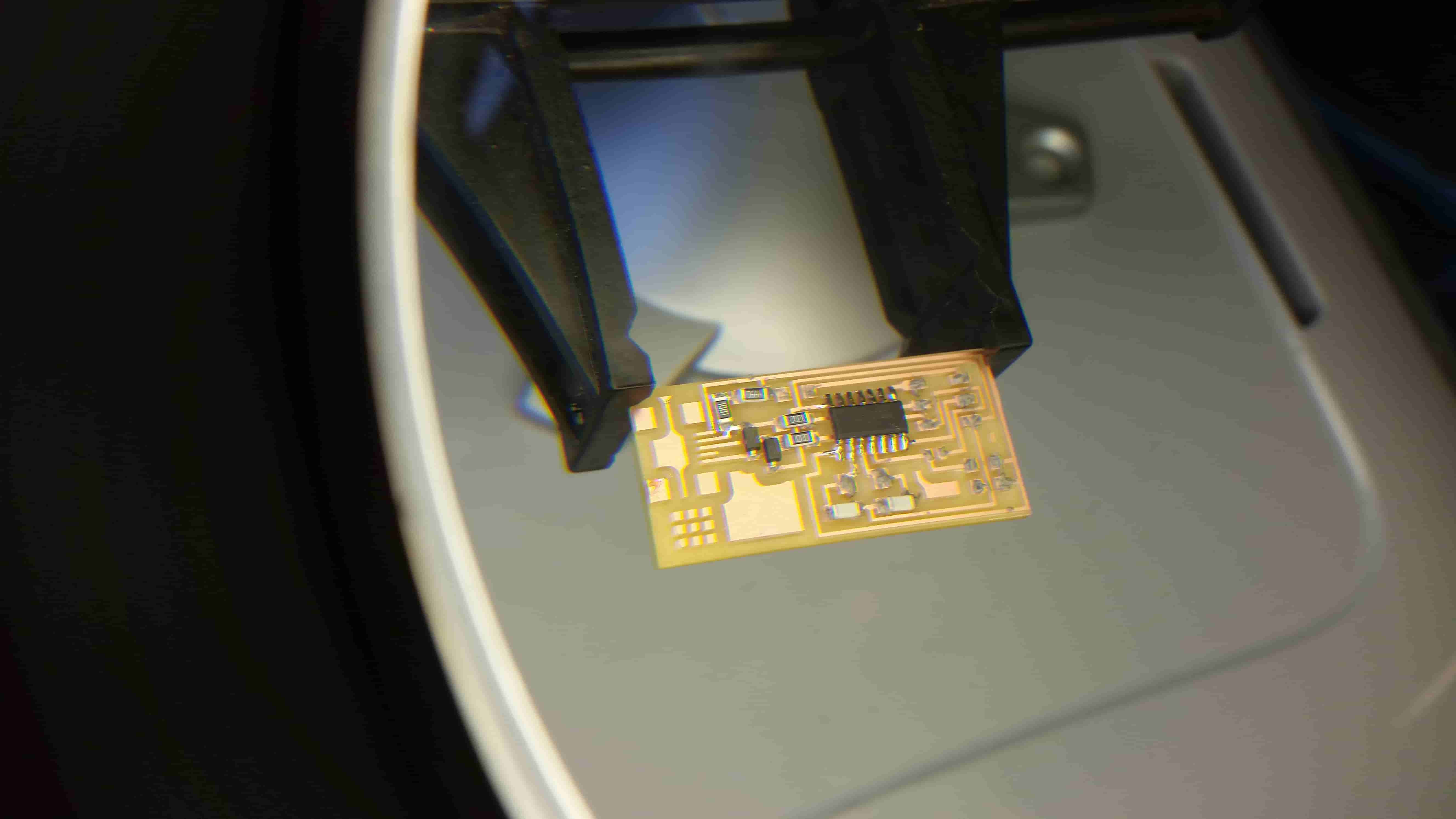
And here it is, our board.
I opted to manually solder the chip on. quickly learning my lesson about soldering SMD; I moved onto re flow.
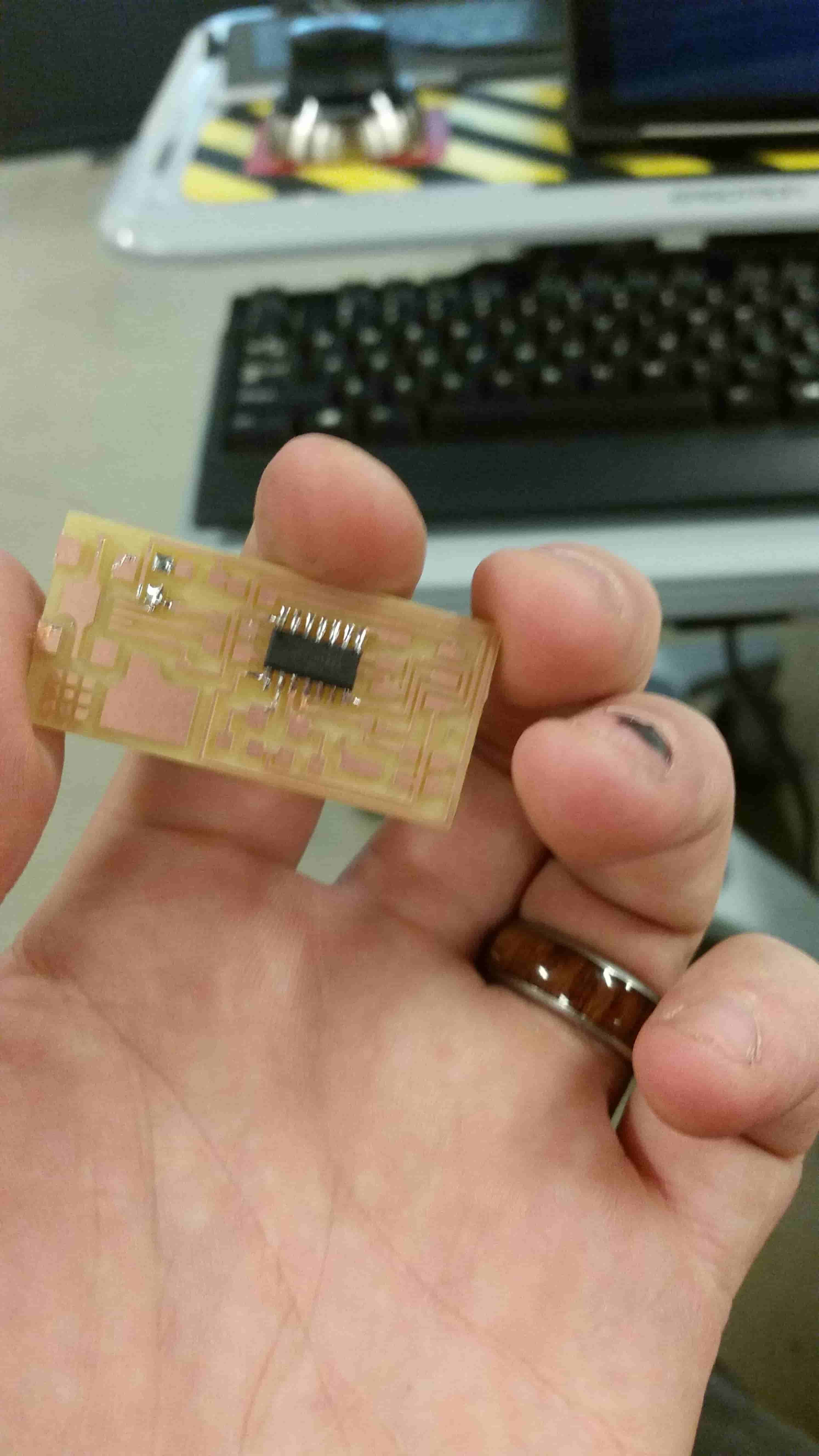
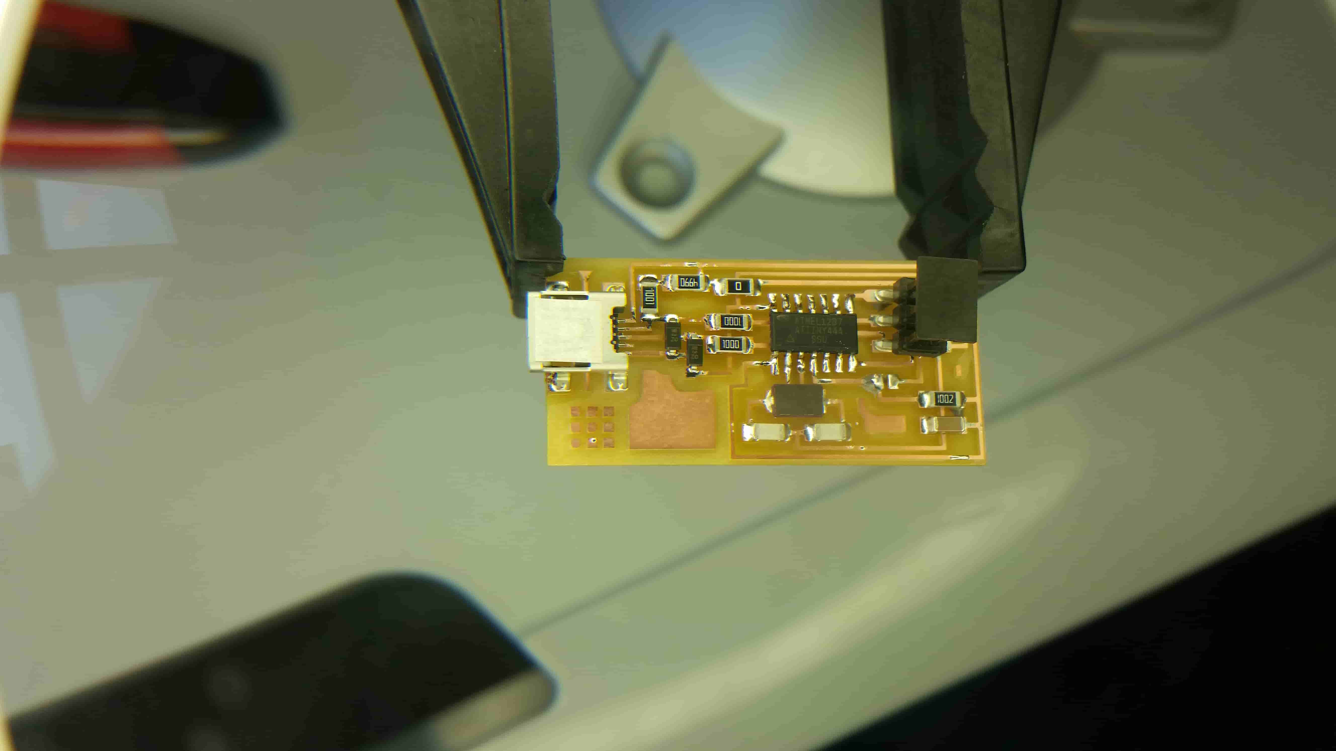
Carefully place the components on top of the solder paste. Once we've got all the components placed
Slowly and carefully run the hot air gun over the components. The solder paste should melt and suck the components into place
Everything is placed. Be sure to either solder a bridge, or a 0 ohm resister at the jumper locations
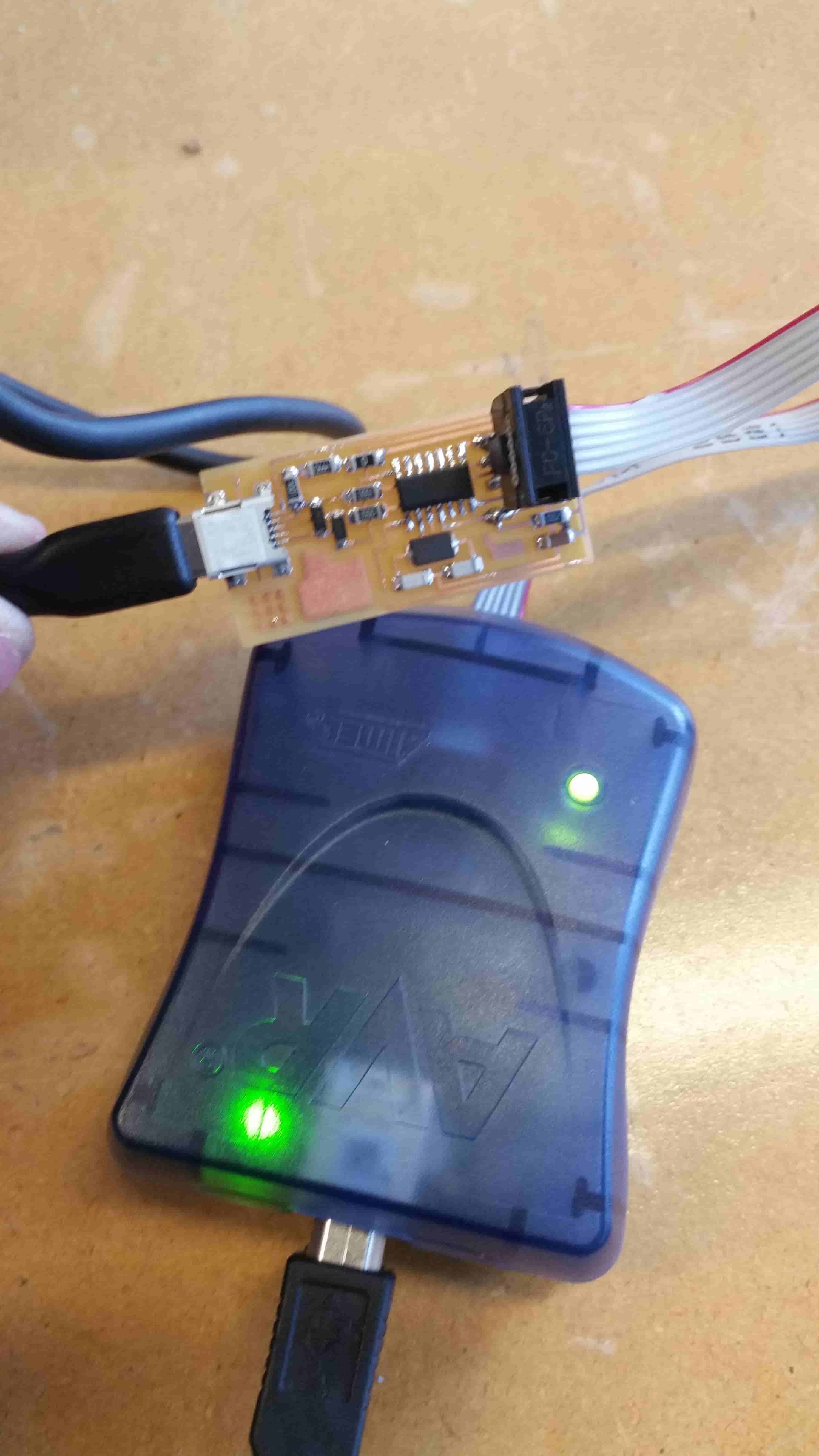
Next connect the AVR to the ISP and run through the instructions listed here
Here is a rich text version of my Console experience.
Here is a web ready version of my Console experience.