We used Eagle (Homepage) to adapt the board that it fits a Sparkfun USB PCB plug. Reasons for this are that you don't need an USB cable to plug the board into an USB port, it is cheaper, and you need one component less.
Step 2 : Soldering
In this step I simply took the finished board and smoothed out the edges.
Step 3 :
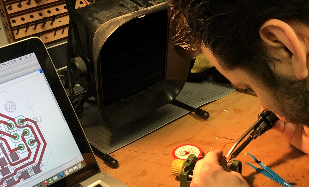
Next step was the soldering itself.
Machine used:
AOYUE Int968 A+
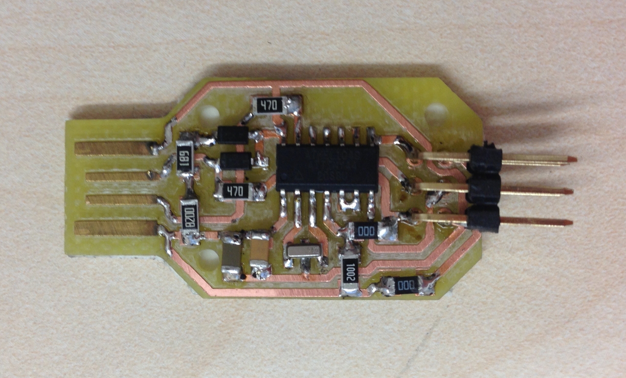
Parts:
Microcontroller Attiny 44 SOIC14
Resonator 12 MHz CSTCE12M0G55Z-R0
2x3 Pinheader 2,54mm
2 x Diode 3,3V SOD-123
2 x 47 Ω Resistor
2 x 0 Ω Resistor to replace jumper for programming reset
1 x 10 kΩ Resistor
1 x 680 Ω Resistor
1 x 720 Ω Resistor
1 x 100 nF capacitor 1206
1 x 100 μF capacitor 1206
Step 4 : Gold coating
In the end I gold coated the USB pins to prevent them from oxidation. For this I used a galvanization kit with a gold electrolyte. I short-circuited the USB pins and soaked a sponge, which was attached to a metal rod, with the electrolyte. I than connected both the metal rod and the USB ports to ground and 3V. The gold covered the USB already after some applications