Exercise 18. Final Project
Project Development - I2C

I have done a lot of research as result of this topic learning everything from hex code to the International Space Station. Here is a link to my resources..
Work Flow
I learned about I2C data bus in exercise 11 - networking
I began by researching ISS Above and PiGlow. According to the manufacture Pi Glow board uses the SN3218 8-bit 18-channel PWM chip to drive 18 surface mount LEDs. Communication is done via I2C over the GPIO header with a bus address of 0x54. This chip is so small I do have the means to surface mount solder it so I bought the PiGlow for $11.00. I am using the PiGlow to indicate to me when the ISSAbove is sending messages. I plan to intercept these messages and to create my own LED indicators or other output indicators.
Proof Of Concept
As proof of concept, I began by using two standard arduinos and the same master and slave code example found in the wire example on the arduino. See exercise 11. This code results in the master arduino slowly increasing an integer. I decided to change the slave code to detect when the integer reach 18. Once the integer reached, Led 13 should turned on. It work as you can see in the this video Proof Of Concept I2C and blinking a light.
#include
void setup() {
Wire.begin(0x54); // join i2c bus with address 54 - Pi Glow
Wire.onReceive(receiveEvent); // register event
Serial.begin(9600); // start serial for output
Serial.println("established");
}
void loop() {
delay(100);
}
void receiveEvent(int howMany) {
while (1 < Wire.available()){ // loop through all but the last char c = Wire.read(); // receive byte as a character
Serial.print(c); // print the character
}
int x = Wire.read(); // receive byte as an integer
Serial.println(x); // print the integer
if (x=18){ added this code
digitalWrite(13,HIGH); added this code
}
}
Raspberry Pi ISS-Above
I began connecting my Raspberry Pi to PiGlow.
I loaded ISS-Above, attached PiGlow and turn on the Raspberry Pi
The Raspberry Pi, PiGlow and ISS Above worked as expectedly. Different color lights blink according to when ISS travels over your local location.
I now needed to add my FabArduino to “listen” to the communication between ISS-Above and PiGlow.
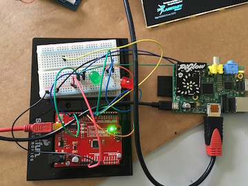
Using the PiGlow data sheet I tried connecting the PiGlow to the Raspberry Pi via a breadboard. I hoped to connect my Fab Arduino to the breadboard as well.
Unfortunately, the PiGlow did not worked unless it was connected directly to the Raspberry Pi.
PLEASE NOTE: I have recently discovered that I needed to connect to ISD and ICD pins on The Raspberry Pi to the PiGlow to make it pssible to run PiGlow without being directly attached to the Rapbery pi.
I solder wired from SDA, SCL and Ground on the Raspberry Pi and connected these three wires to SDA, SCL and Ground on a redboard Arduino. Once it works this way, I will connect to my Fab Arduino.
On the advice of Dr. Harris, I installed CoolTerm. CoolTerm is a serial monitor software package that will show Hex code which Arduino Serial Monitor does not.
I ran the following program on Arduino. This was based on the examples found in Arduino software and the wire library.
#include
void setup() {
Wire.begin(0x54); // join i2c bus with address 54 - Pi Glow
Wire.onReceive(receiveEvent); // register event
Serial.begin(9600); // start serial for output
Serial.println("established");
}
void loop() {
delay(100);
}
void receiveEvent(int howMany) {
while (1 < Wire.available()){ // loop through all but the last char c = Wire.read(); // receive byte as a character
Serial.print(c); // print the character
}
int x = Wire.read(); // receive byte as an integer
Serial.println(x); // print the integer
}
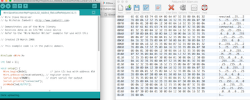
Once the Arduino program was running, I started CoolTerm to monitor serial output.
I started up Raspberry Pi, PiGlow and ISS-Above. The serial monitor showed data traveling from the Raspberry Pi to PiGlow. When PiGlow lit up, the serial monitor screen filled up with data. View ISS-Above code traveling from the Raspberry Pi to PiGlow using I2C.
I captured the data. I also referred to PiGlow documentation and I determined that 0X07 referred to the red leds on the PiGlow. The ISS-Above uses the PiGlow to indicate how long it will until ISS flies above your location. The number of time a red Led blinks on the PiGlow tell you how many hours until ISS is overhead. The 0xB6 code turns on white leds which indicates the ISS directly overhead.
If I could test for 0xB6, then I can turn on my own LED, control a servo or perform any function I wish when the International Space was overhear.
I am looking at two bytes of information so I tried the following code. I will just show you what I changed from the last code.
// while (1 < Wire.available()) { // loop through all but the last charc
int x = Wire.read(); // receive byte as an integer
Serial.print(x); // print the integer
if (lowByte(x)==0x07||highByte(x)==0x07) { /// checking for either bit to be 0x07
digitalWrite(13,HIGH); // turn on LED
}//end if
The LED never turned on even when the red lights blink on the PGlow and I could see ISS-Above sending 07.
After speaking again with Dr. Harris, I followed some of his suggestions. These included changing charc to unsigned charc to increase the range from 0 to 255. I also tried to format the intenger to be in HEX format (c, HEX)
I still got the same results. Next, decided to start the loop at zeo, since we might be missing a bit starting starting the loop at one
Here is the section of code
void receiveEvent(int howMany) {
while (0 < Wire.available()) { // loop through all but the last CHANGED
unsigned char c = Wire.read(); // receive byte as a character
Serial.print(c,HEX); // print the character
if (c == 0x07)
{
digitalWrite(13,HIGH);
}
}
}
IT WORKS !!!!!!
Click here to see turning on a Led by scanning the I2C
Next, I decided to check for several values. These values reflect LED locations on the PiGlow.
void receiveEvent(int howMany) {
while (0 < Wire.available()) { // loop through all but the last
unsigned char c = Wire.read(); // receive byte as a character
Serial.print(c,HEX); // print the character
if (c == 0x07)///red led
{
digitalWrite(8,HIGH);
}
if (c == 0x06) //green
{
digitalWrite(11,HIGH);
}
if (c == 0x05) //blue
{
digitalWrite(13,HIGH);
}
if (c == 0x0B) //white
{
digitalWrite(9,HIGH);
}
}
This work as expected. Click here to see turning on a multiple Led by scanning the ISS-Above via I2C using a sparfun arduino
Now I tried it on my Fab Arduino and it worked as well. Click here to see turning on a multiple Led by scanning the ISS-Above via I2C using my Fab arduino
Videos
- Proof Of Concept I2C and blinking a light.
- View ISS-Above code traveling from the Raspberry Pi to PiGlow using I2C.
- Turning on a Led by scanning the I2C
- Turning on a multiple Led by scanning the ISS-Above via I2C using a sparfun arduino
- Turning on a multiple Led by scanning the ISS-Above via I2C using my Fab arduino