Final Project Process
Note: My code and files can be found here in a zip file. I am only posting low resolution photos on this page. Week 17-19 Final Project Folder Zip
Designing the Sculpture.
Throughout the class I have been scaffolding my weekly projects to help build this final project. I have been doing various sketches and c.a.d. work to help along the way. I was constantly reflecting back to earlier work in weeks past to finally design my sculpture.
Brainstorming the Final Design
1. I knew that I wanted to work big and on the Shopbot.
2. I knew I wanted to design a sculpture that I would find interesting, whimsical and an homage to the fields of the other people on my team in biology, in technology, and engineering.
3. I knew I wanted LED display to mimic bioluminescence.
4. I knew I wanted a moving kinetic element for the "Lure" and decided on a stepper motor.
5. I knew I wanted the sculpture to react to the abscence of light and display when it got dark.
Here is the inkscape design I decided upon and would work toward its 3d manufacture and creation.

From my past work I had a concept so I started there.
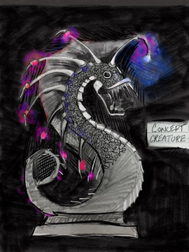
I tried to remain as true to the concept as I could with several conciderations.
1. The sculpture would be press fit, so I would have to work to get it out of a flat 2d shape and occupy width space.
2. It would not have a base so I would have to design legs to make it both self-supporting and stable. The latter is especially true because it was going to be 8 feet tall so it would need a wide base.
Drawing The Creature in Inkscape
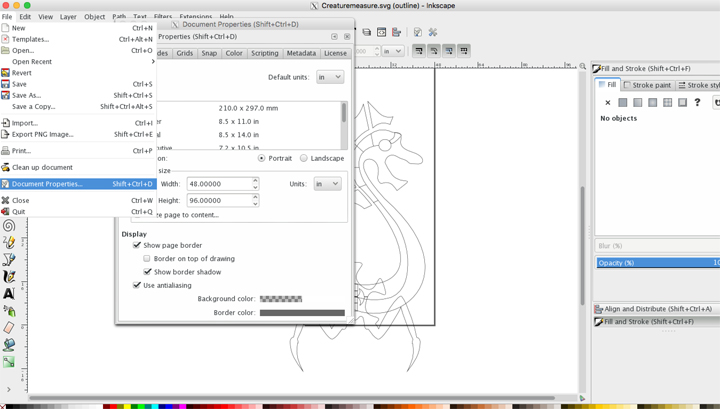
1. The first thing I did was set up my preferences in Inkscape. I chose the preferences I did so that I could easily move them over to VCarve or Aspire to mill the parts out on the Shopbot. I set the custom width to 48 and the height to 96 inches and default unit to inches from pixels. This is the size of the panel of wood I would be using to mill out creature parts.
2. I referred back to the concept drawing and began to draw the creature.
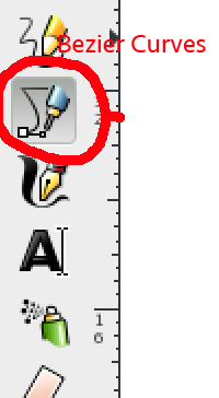
3. I used the Bezier Curves tool to draw out the design. I love this tool because it makes it extremely easy to get elegant curves and to correct mistakes, although when you are used to drawing freehand it takes a while to get used to.
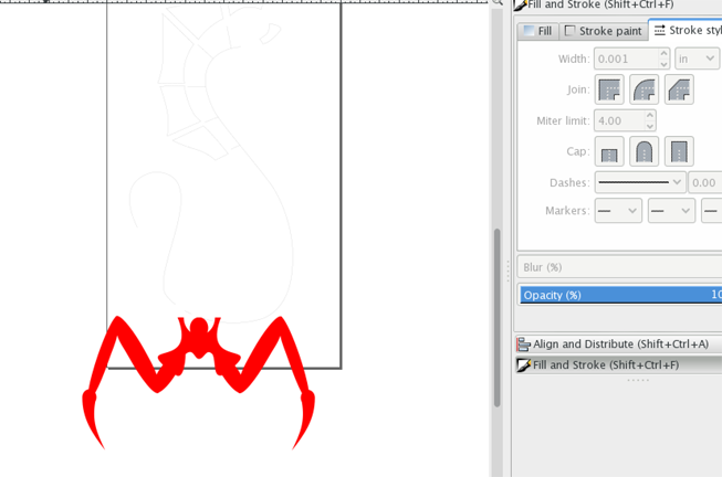
4. My Stroke Line and Fill in inkscape varied on what I needed and what I wanted to see. I was used to setting the stroke to .001 for laser cutting, so I continued to use that setting. It must be said that this setting (.001) makes it impossible to see when viewed in normal view so you have to go to view, outline.
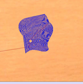
I used the fill function on some objects when I wanted to see the shape, especially when I was making artistic decisions on form. You can see I did this in the image below while I was working on the creature’s legs.
Here is a screen shot of the creature being drawn out in inkscape.
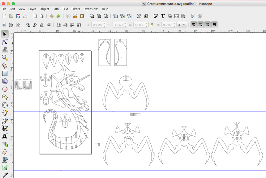
In this screenshot you can see a bunch of things happening.
a. I started putting in lines where I would like the shopbot to cut out pockets and electric wires for the LEDs and the stepper motor
b. I have started labeling different objects, so I could keep everything organized and refit when the time comes.
c. I started to put in slots in different objects. This will be covered in more detail in a later section of this process page.
d. I started to think about milling out molded parts that would be cast later.
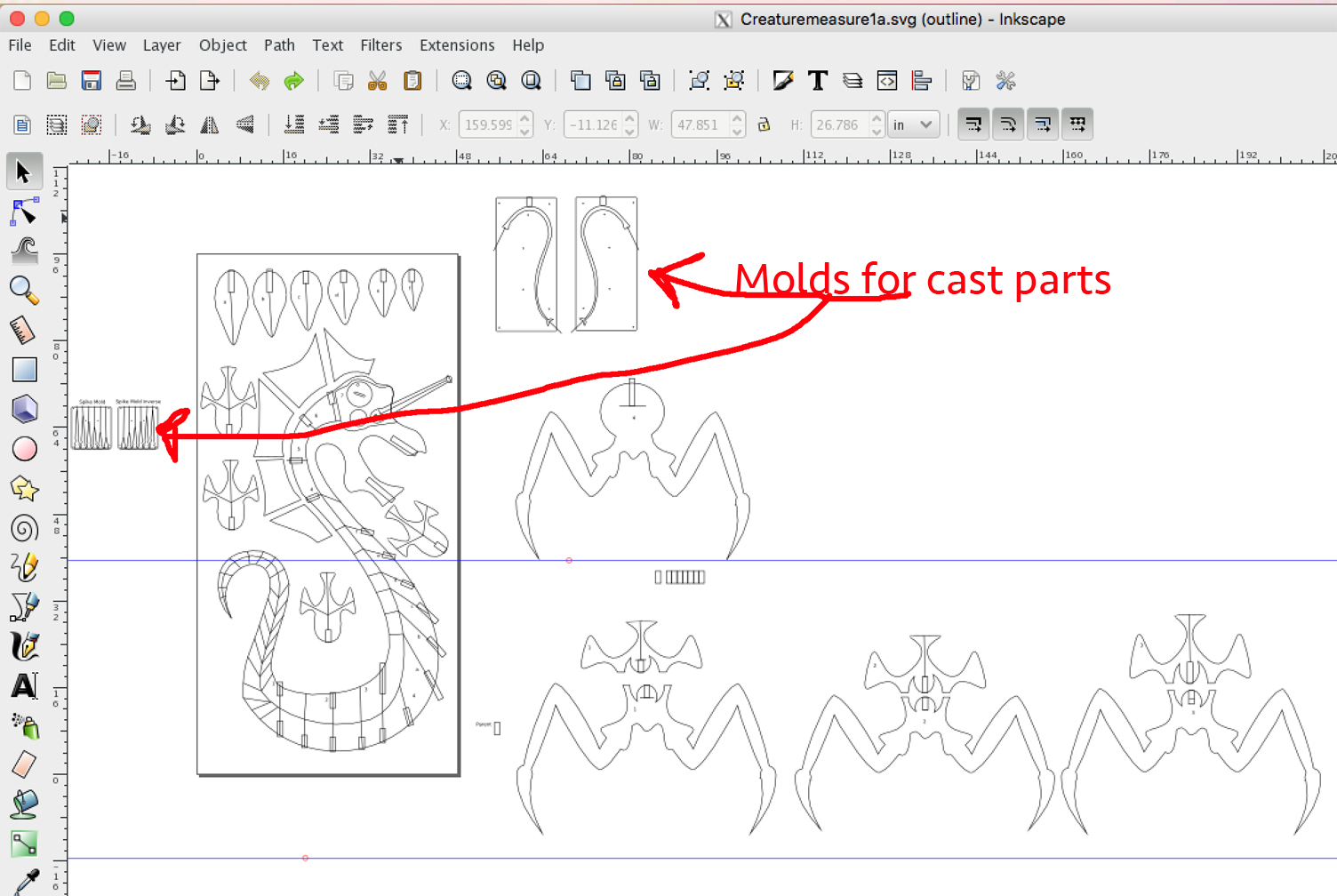
e. I quickly realized that I had way too many parts to fit on a single sheet of 96x48 plywood so I would have to start making different sheets for other parts of the creature. To compound this was that I was planning on doing an inverse of each piece so that they could be put together and the wire pockets would all disappear. It looked like it was going to take 6-8 sheets of Plywood and that was without any screw-ups on my part.
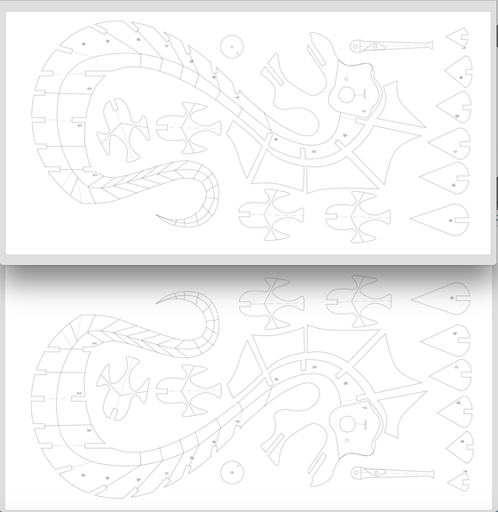
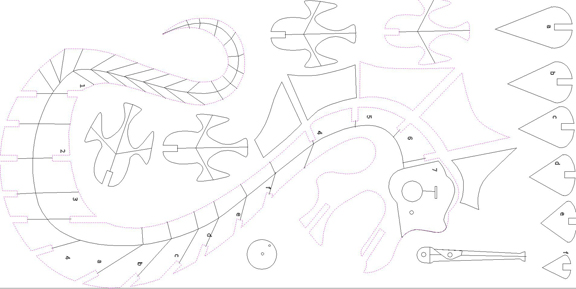
The final Creature Inkscape design in six sheets.
Sheet 1 and sheet 2 (Inverse)
Sheet 3 and 4 (Inverse)
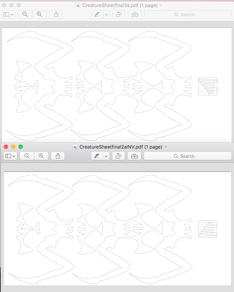
Sheet 5 and 6 (Inverse)
.png)
Six sheets, wow! This was going to be a lot of milling. In these screenshots of the PDFs you can see that I took my drawings and turned them 90 degrees so that they would be oriented to the bed of our shopbot. I learned this the hardway. When I imported them into Vcarve they did not fit on the work surface. I could have changed this in Shopbot, but it was much easier just to go back and do it on the PDFs in inkscape.
I did have a few problems when I created the inverses of each sheet. The main problems came from being late at night and working without much sleep
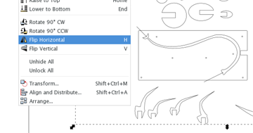
When you select all the objects on the page and then hit the flip horizontal, it will only orient the shapes individually... which didn't work for my needs. You must group all of the selected objects into one object to get them to flip to work correctly and stay in the same page orientation.
Almost ready for the Shopbot, but first a little about the slots and Parametric design.
When creating slots for a press-fit sculpture it is extremely important to get the exact measurement of the thickness of plywood that is going to fit into the slots. Before I could finish the Inkscape designs I had to make a swatch and mill it on the shopbot to test what size I needed to make my parent slot, so that all the clones would be the same size.

After measuring the plywood I chose the .948 slot. This, I would later decide, was too tight. In the future, I would choose a less tight fit to allow for paint and ease of assembly. It also must be said that I live in a very humid climate during the summer, the southeastern US. I am pretty sure this humidity caused some swelling in the wood.
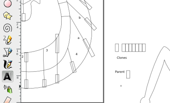
Now putting the cloned slots into the sculpture.
a. I created a rectangle and cloned it 48 times. I would need a lot of slots.
b. I then placed the slots where objects would be attached.
c. After I got the .948 measurment, I went to the parent and ajusted the width to .948 and parametrically all the clones switched to.948 width. This is a huge time saver for labor.
d. Now I had to change the clone rectangles into slots in the object they were embedded.
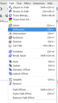
e. To do this you have to delete the parent clone. If you do not do this you will not be able to take the difference of the the rectangle and the object you are creating the slot in.
f. Next select and click the object needing a slot. Make sure that it is ungrouped and while holding shift, click a cloned rectangle. and then go to object and select difference. This should create the slot.
Milling the Creature Sculpture on the Shopbot.
In week 7, we covered shopbot operation and my notes can be found here.
Fab Academy Files, Week 7All of these files can be found here.Vcarvefiles
The object being milled was large and complex. This was an enormous task. What I thought would take a day or two, took me seven days. Neil Told me that jobs like this usually tak pi x the time you think it will take to finish. I would agree whole heartedly. It then another 3 days of hand sanding. Be forewarned, in the future for my sanity I would chose a smaller size.
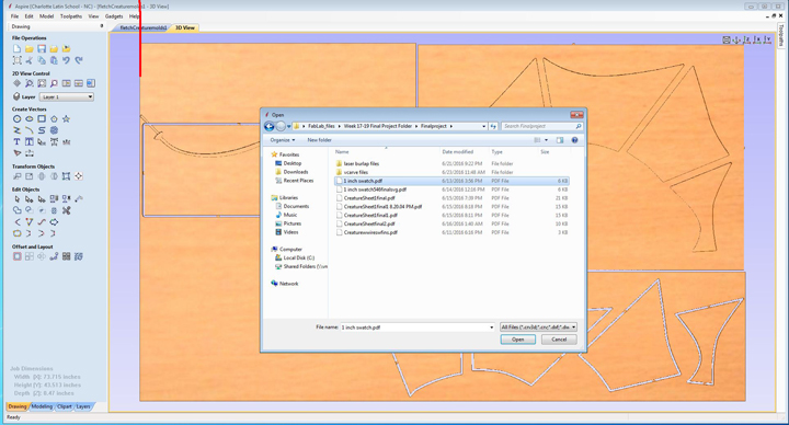
Step 1. In Vcarve or Aspire and open the saved PDF file that is to be milled. Make sure the settings for the job are correct. I measure every piece of ply and write that number on the wood so I dont forget. The width of each piece of wood I used was usually about .470 inches deep.
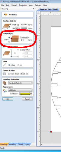
The Job size should remain unchanged as it was established in the Inkscape document that was imported or opened.
Step 2. Add Dogbone Filets to the interio of the slots. You can not do this in Inkscape and you need to so that all the slots will fit together snuggly. The dogbone allows a 90 degree corner to fit in a slot by a round bit.
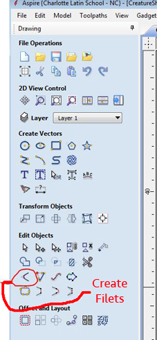
a. To get to dogbone filet select the style.
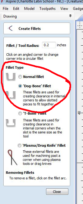
b. Press the right angles where you would like a filet. A filet looks like the example below when done correctly.
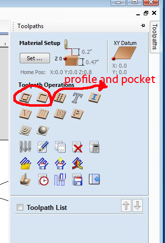
Step 3. I was ready to start my Toolpaths. There are many different types of cuts, but for this job I only used two. Profile and Pocket.
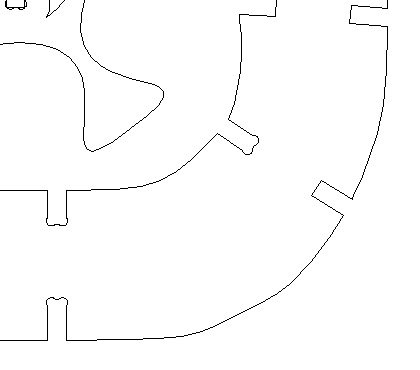
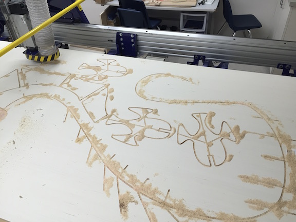
a. Most of my cuts would be profiles going all the way through the wood. To do this I selected all the objects that would need to be cut out, as I selected them their profiles would turn pink, as seen in the screenshot below.
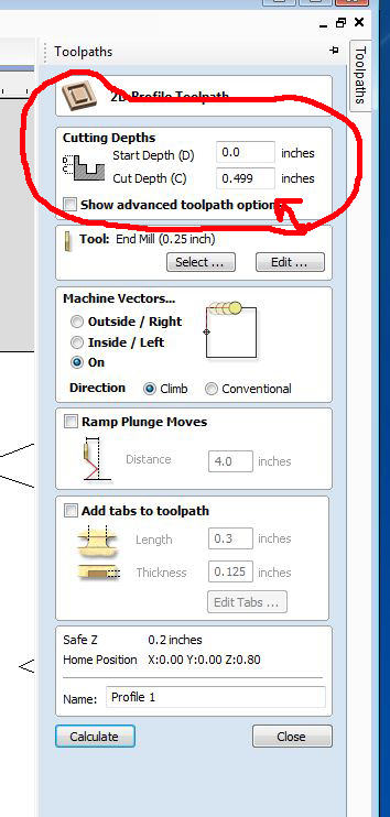
b. When setting a toolpath profile for cutting selected objects out, I chose a depth of .499 that would clearly go through the plywood that has a thickness of .470 and for wire trails I chose a depth of .25 -.15 that would be about halfway through. Below you can see where to set this under /toolpath/ profile
Next make sure you have the correct tool. for Profile cuts I used a .25 down bit.
d. Next is the Machine Vectors and this is a critical, Critical step.
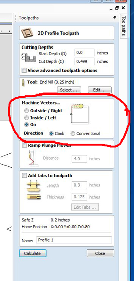
d1. I really messed up here, as I was not thinking clearly stayed up late and, as a result, used the wrong setting on the Second sheet I was milling. As you can see it shows ON as my selection choice , but for all of my cut out profiles, I needed to chose Outside/right. When I ran it on ON all of my cut out pices were to small and useless. It cost me time and materials. Becareful what you chose here and make sure and double check what choice you made. I did not have time or maney to lose.
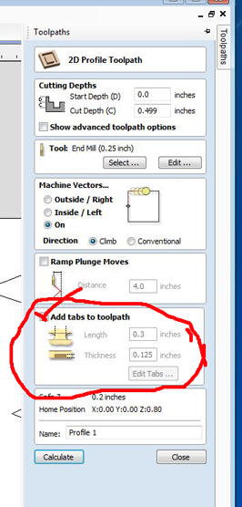
e. Tabs for everything that is cut out has to be secured to the original board with a tab. If not it can go flying off the shopbot or move and cause an error in cutting. Either is bad. I tend to put to many tabs down for fear of this and it causes me a lot of work afterward chiseling out tabs.
Using the tab tool is easy, after clicking add tabs to tool path just left mouse click where on the tool path you want the tab.
Pocket cuts take a long time. They turn a lot of wood to dust so be prepared. I used pocket cuts where I wanted to put the moving mechanisms and motors and processor within the sculpture. It works much the same way as profile cuts.
1. First select the area that is going to be pocket cut making sure it turns pink.
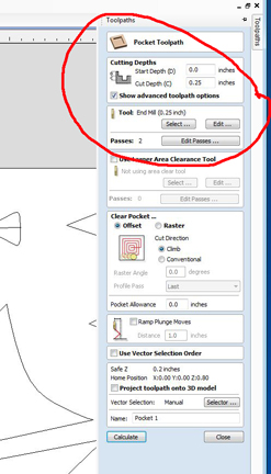
2. Choose the depth of the cut. Most of my cuts were .25 inches deep.
3. Choose the tool . For Pocket cuts were instructed to use an up bit, which is different than the profile cuts.
4. Machine vectors for pocket cuts vary. I used Onfor wire lines and Inside left for space pockets.
5. The useful thing about pocket cuts is that you can cut a pocket between two different objects. I made use of this in many of my designs,especially to create pegs for movable parts.
In the image above the long distance a toolpath is cutting, the route travelled is in blue.
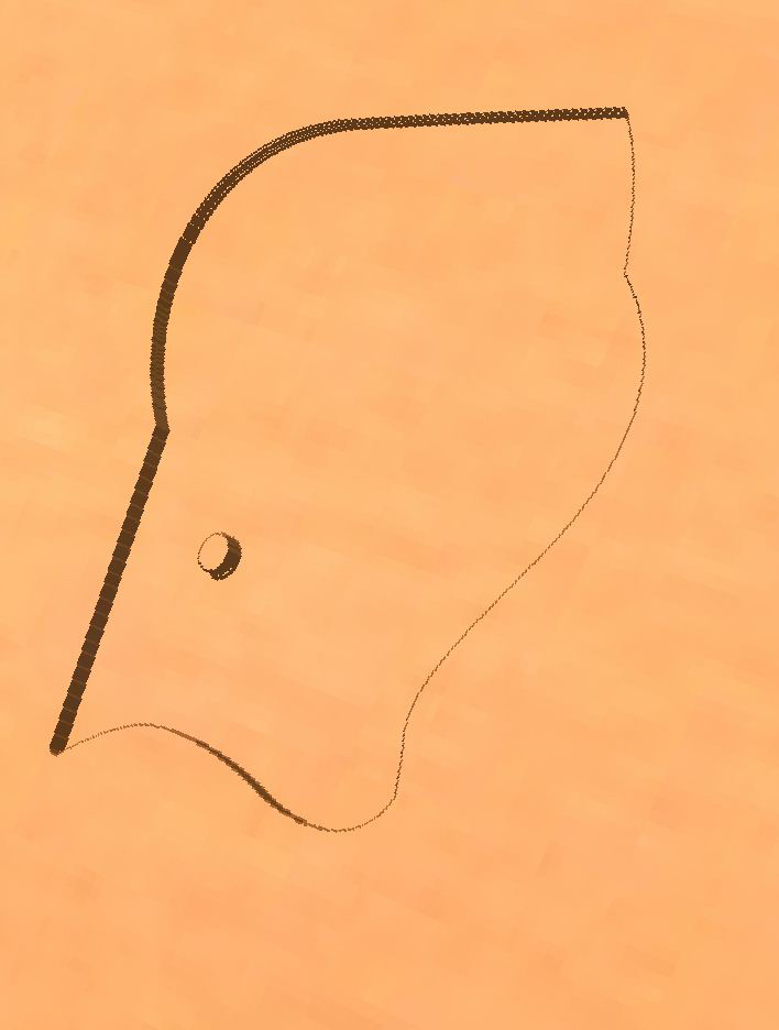
The image above I made a peg to attach the Lure to. It remained uncut as the pocket was cut around it. This was a very useful tool.
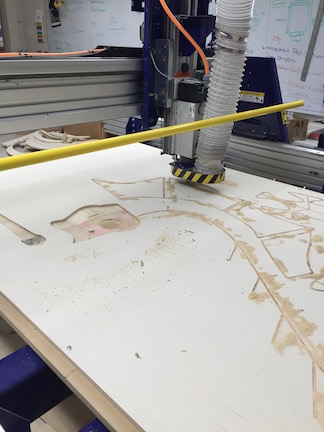
Shopbot Milling day 1
Shopbot Milling day 2
Holding up the Creature Body
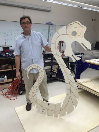
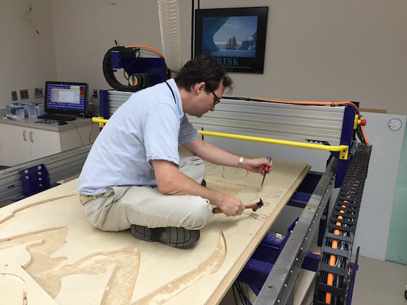
After a week of milling my parts were all finished and cut. I just had to chisel them out. The 75 odd parts ,however, would have to be sanded and painted.
Tricks I learned for successful slots
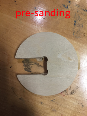
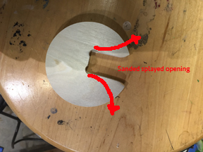
I have access to a nice bench grinder that I used to sand out the inside of the slots when they were too tight. I learned a trick of splaying out the slots toward the slot opening, Doing this on the grinder to really help assembly.
Below is a picture of a splayed slot cut and sanded.
Little circle with slot before sanding
Little circle with sanded splayed slot.
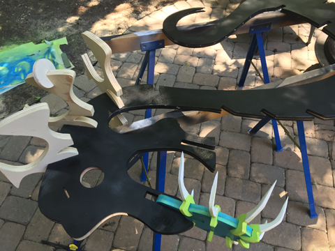
Pre Assembly for fit
Because the sculpture is so big and because there are so many parts it took a massive ammount of time to sand and paint the parts. This needed to be done before the I needed to sand it and paint before I went to wire it and put in all the mechanics. I realiise that I will probably have to touch it up a bit after it is all complete.
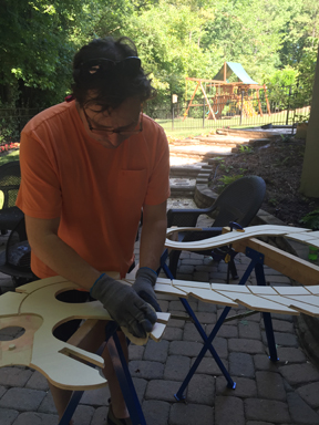
Sanding and Painting took 3 days. It is a very time consuming process, which is especially frustrating when you have a big time crunch to get this project in on time.
Here is a video of me sanding the thing.
Me sanding some more.. and more
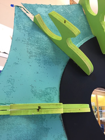
Painting beginning.. I decided on a throw back color theme a mix of 60's and 80's neon
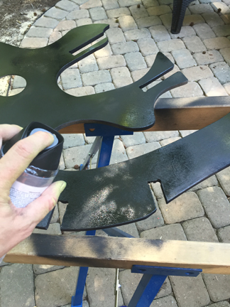
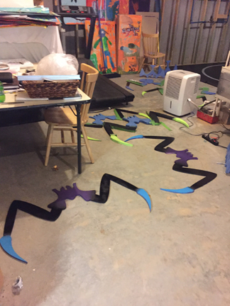
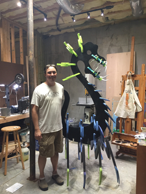
Finally, finished the first coat and the size is starting to show.
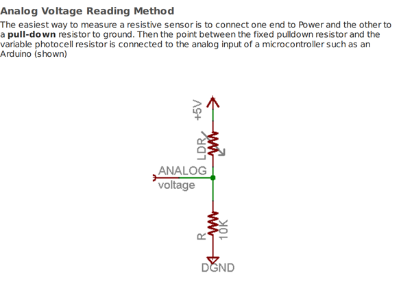
Input- Photo Sensor or Light Sensing Diode
The input of my sculpture would be a light sensor that would read light values. When the ambient light gets dark enough the photo sensor will activate the LED's and Lure assembly (stepper motor) on the sculpture. I was familiar with this idea, as in Excercise 11, I had done something very similar. The link to that week can be found here.
Week 11,input devices, Light SensorHowever, the photo sensor I was using for my sculpture was going to be different than the one that I put on my board in Week 11, so I had to make adjustments.
For my sculpture I was going to be using an Adafruit Photocell, a link to its description can be found here. www.mouser.com, Photocells.pdf
Of important note is that LSD are not very accurate. To get one to work, it is best to test it to see its range. I was going to have wire one together and then set a test to extablish its range so that I could code it properly.
Wiring the Photocell
When working with Adam Harris, he showed me the proper way to rig a light sensor. He drew a schematic on the board that I could follow.
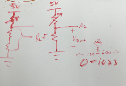
Then I did further reasearch on www.mouser.com, Photocells.pdf and found another schematic. Our Lab did not have any 10k resistors so I had to go with a 5.5k OHM resistor
Here is a pic of the the other Schematic off of www.mouser.com
After I wired and soldered the 5.5k resistor, light sensor and wires I was ready to test.
Here is a video of the test and the results.
Light Value in well lit room = 875
Light Value after lights were turned off = 253
I needed to get a value for my If/Else Statement in my code. If the lights dropped below this value the sculpture would activate, if not the the sculpture would remain inactive.
To establish this value I split the difference and took the midway value between 253 and 875. That came to 564 as my set value.
The code I ran for my test was basically the same as I had used in my Week 11 excercise called "The Grue". Week 11,input devices, Light Sensor I was able to use the code because it printed the sensor value on the serial monitor as highlighted below I knew that I would have to rearrange the if/else values when I put this in the code for the sculpture.
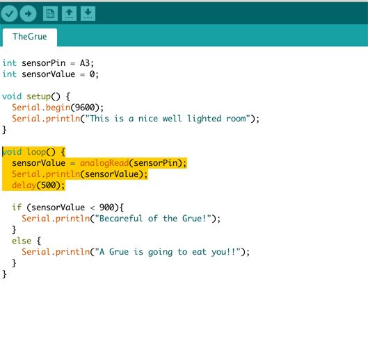
The Arduino Testcode can be found here. FabAcademy , Light Sensor Test Code, The Grue test Code
Output I - The LED's
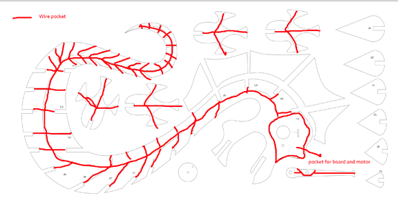
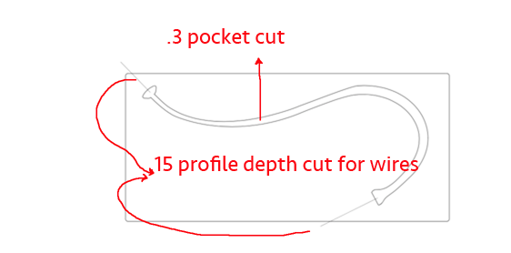
I had planned for wiring from the beginning. I didn't want the look of the sculpture ruined with wires peeking out, but it also had to be very functional and work the way I intended. I decided to channel groves in the inside of the sculpture on the shopbot. I talked about this in the very beginning of this page when discussing CAD work.
1.I groved the entire sculpture for wire, but I knew I would not have time before this was due to wire it completely. It is my hope that I come back later and wire the entire sculpture with LED display from head to tail.
2. I started putting in lines where I would like the shopbot to cut out pockets and electric wires for the LEDs and the stepper motor
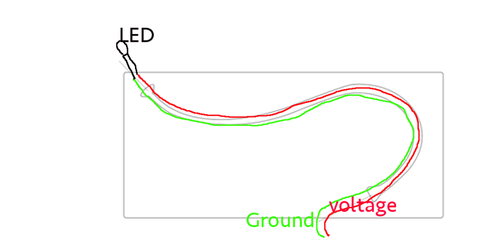
Here is a sketch I made to help me understand what would go where.
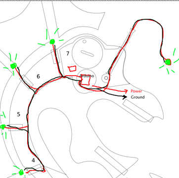
3. I now started placing my wiring and LED's in the sculpture. I decided to wire my led's together in a parallel fashion, instead of serial, so that if one did not work, they all would not fail. I looked at my sketch above.
4.I chose very then wire I scanvenged from a bigger CAD 5 wire. Inside are bundles of paired wire. There is a color and then the same color with a white stripe in each pair. I chose to make the white striped wire always ground, to eliminate confusion on my part.
5. After talking with my my teammate Tom Dubick, I decided that I should put a resistor before each LED to reduce the current going to the LED and keep it from burning out. There are some very good tutorials and some resistor calculators online. I used the instructables below.
Wiring LED's in Series and parallel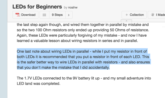
We had a limited amount of resistors and unfortunately, they have been mixed up quite a bit. I had to use some resistance measuring tweezers to get the right ones.
6.I decide to test a 150 Ohm resistor with a blue LED to see how it worked. I put it in a breadboard and used a nine volt battery as a power source. Below is a picture of the test.
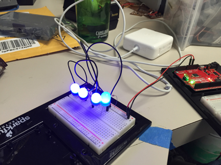
The above test is 3 LEDs with a 150 Ohm resistor and one with a 400 OHM resistor. I liked the brightness of the 150 ohm resistors so I went with those. The 400 is the dimmest one in the picture.
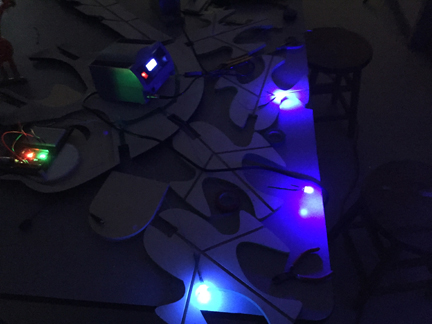
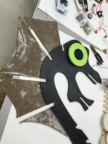
After a few hours, I ran wire and soldered on all the LEDs. 4 Blue Gumdrop LED's and One Green Gumdrop LED on the "lure". I wired the green LED light sepperately because I wanted to, time allowing, have its own program.After every LED I would solder I would hook up the power and test to make sure it all ran. Below is a picture of one of those tests. I would turn out the lights to get the full effect.
I then started laying LED wires in the preslotted groves to prepare for final assembly.
This was a big step for me that I had cleared. Next Up, Getting the stepper motor wired and running.
Output II - The Stepper Motor
Last night I was able to wire the stepper motor to an Arduino and program it . It ran but with mixed results.
Problems List
1. The stepper is only running in one direction I need it to run in clockwise and counter clockwise motion.
2. The stepper is very weak. So weak in fact that a piece of scotch tape flapping around can cause so much resistance that the stepper fails and will not spin. I think the cause of this is too little voltage and current powering it. My power source was just the power off the usb so I am going to try testing a 9 volt after doing some research and conferring with teammates.
3. There are too many connections in my wiring to the stepper. To get the Stepper Motor to the Arduino I needed male to female connections and also, female to female. This has caused some areas where shorts have happened and I need to simplify the wiring.
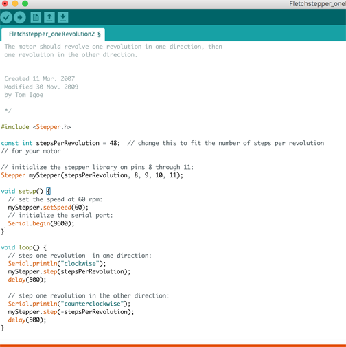
Here is the test of the set up. The Mosfet Transistors would be wired directly to pins 8,9,10,11 of the Arduino.
In the video, I incorrectly state that it is a code for one rotation... However, it is a two rotation code. One Clockwise, delay half a second, one counter clockwise. Something is clearly amiss.
Besides the programing being off my stepper motor, as stated earlier was just not strong enough to engage and move the "Lure" mechanism of my sculpture. It was just too weak.
Solutions to this Problem.
A. Scale back the Lure drastically, to decrease weight, so the stepper could power it.
B. Build a Gearbox to increase the work the small stepper could do.
C. Get a bigger Stepper motor.
D. Any combination of the above.
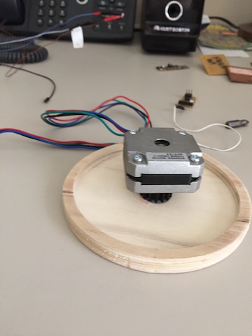
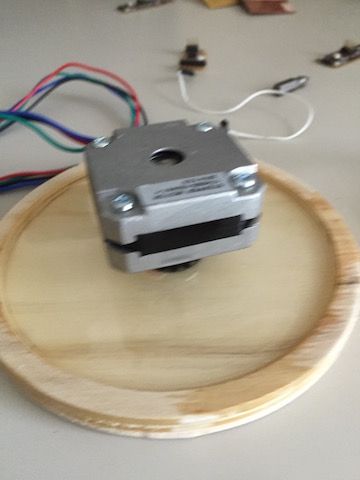
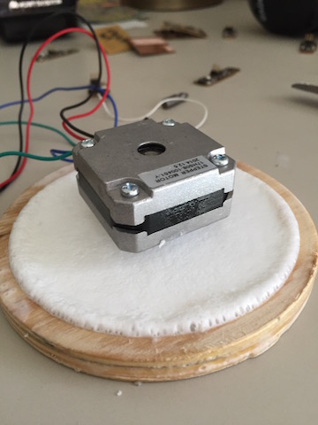
With time running out I decided to choose option "C". Our lab had some old Polar 3D printing machines and I ended up salvaging several from the broken down machines. A picture of the new stepper is below. Former FabLab Graduate, Adam Harris helped me through what I needed to do and walked me through the process.
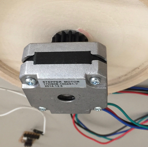
Adam explained the differences between the stepper I had been using and the new one. This new stepper would be bipolar and need a breakout H or half bridge board to supply current in both directions for the stepper to work correctly. The old stepper had 6 wires and four coils unipolar, where as the new one only had 2 coils.
42bots does a great job explaining this and I went there for additional reading and research. 42bots Bipolar Stepper
There is also a great wiring tutorial and I read over that again. It can be found here,42bots Bipolar Stepper, Wiring How To.
The biggest difference between the Mosfet break out boards I had made before in Week 13, Outputs. In this board I would need to use both types of Mosfets to steer current in the proper direction. Here is an example of the H board I would need.
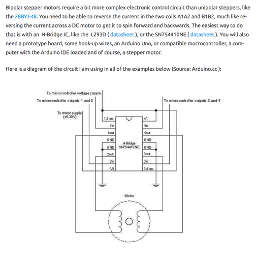
The difference in this Hbridge schematic and the one I would need is that we would not need the enable pins.
Here is the design I used from Adam for my H board.
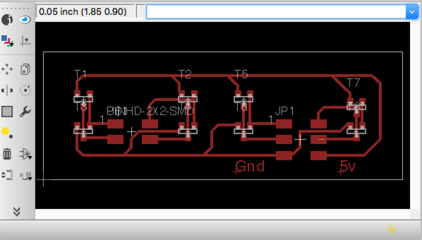
The schematic and the board eagle files can be found here. EagleCad for Creature Hbridge boards.
The board is a simple one, it is only 6 parts.
2x4 connection header
2x2 Conecction header
4 Type N mosfet Transistors Across Top
4 type P Mosfet Transistors Across Bottom
However, there were a few problems.
The traces were too big in some areas and the Othermill could not mill them out. I had to go back and cut them with an exacto. I milled two boards in hopes that I would be able to get one to work.
Here is a photo of the milled and soldered Hboard.
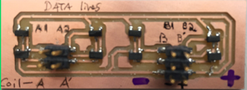
Wiring the stepper was not so hard. I used a 4 pack of Double A batteries for the power.
As Seen on the photo, lines A1 A2 B1 B2 are date lines and would be assigned an Arduino pin. A, A', and B,B' would correspond to the stepper motor coils. Wires Voltage and Ground are marked +,-.
As always I loaded the program onto the Arduino to test if it would work.
After getting the stepper wired and assembled I researched code. Here is where I looked.
Example Stepper CodeHere is a video of that process. It worked great so it would be viable for my Satshakit Fabduino.
Code
I have found I have a lot of weak areas in, amongst them is coding. I have attempted to reason out the logic in this simple sudo code. Before I cobble actual arduino code together using a if, else statement.Here is a picture of my Sudo code to frame what I wanted to do.
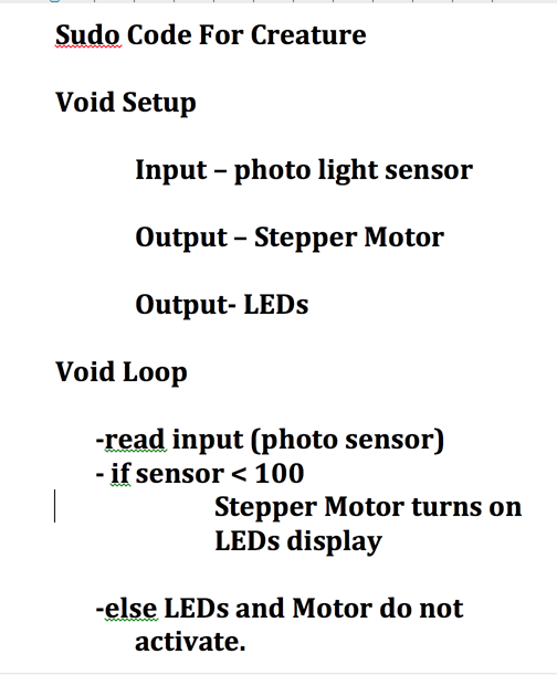
The final code was cobbled together using modifide code from my past lessons. I used the some of the lessons from Week 11,input devices, The Grue
I used some of the Blink code from Week 8 Embedded Programming
.The last part of code was taken from Example Stepper Code
I had to work with it a bit to get it to do what I wanted, and looking back I would keep the lure light on all the time, but I am happy with the result. The final code I used is here, labeled as Finalcreaturecode, Week 17-19 Final Project FolderAccessories
I tried to work in every machine in the lab with these. To avoid redundancy. I will refer back to past weeks for a description of the specific processes.
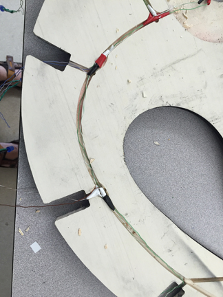
Composite Webbing between Fins
For the webbing between the back fins I decided to use composites with resin and Burlap. The process can be found here Week 14, Composites
I used inkscape designs for the fins and cut them out on the shopbot.
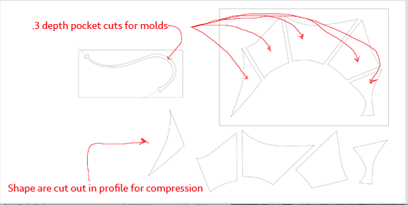
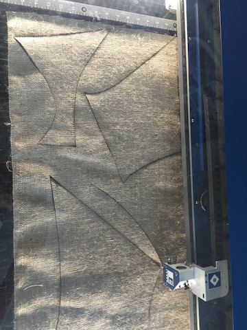
Then I cut them on the laser cutter.

Placed them for size in the molds.
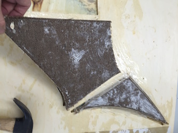
Applied resin and hardener, mixed per directions, compressed them and waited 5 hours. Then, not without a little effort pried them from thier molds.
They fit perfectly down the creatures back.
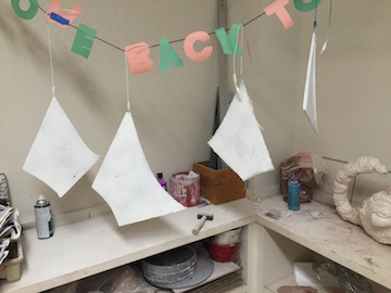
Then they were hung up to paint.
And glued onto the back of the creature with a 5 minute epoxy.
Because of inkscape the fit was amazing.
Below is a picture of the pdf I used to cut the fins.
Mold and Cast Lure Assembly
For the lure I wanted to apply theWeek 12, molding and casting
I used som of the same molds from the resin burlap composites that I had previously made on the shopbot.
This was hit or miss for me. I did learn one important fact. The plastic we use to cast, expands during the mold making process. I was using the shopbot so much that I thought I would make molds on the spare parts of my creature sheet design, that way I could use extra space on some of my boards, like shown below.
This idea was no good. Because the plastic expands, it is too hard to pull out of the wooden molds. I later realized that is the exact reason you should use the Silicon rubber with the mold, that way the plastic has room to expand as the plastic hardens. The silicon rubber is used to expand with it.
I was able to use one cast and mold. the one I made for the lure.
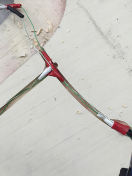
This mold was fun because I ran wires though the length of the mold enough so that I would have excess to solder an LED on.
1. I ran red and green wires down the length of the mold and tested to see if they worked .
Here is a simple video of this.
2. I ran out the wire cuts and sealed the wire cuts with silicon. This was to make sure the liquid plastic would not run out of the mold.
3. I used wax as a releasing agent. It was somewhat effective.
4. I mixed and poured the plastic and waited for it to harden.
There are lots of pictures of this process. They are located here.
Final Project Molding and casting.5. The important thing I learned was that I was not able to pull the plastic out of the wooden molds if I waited to long. The plastic cures and hardens in seven minutes. The only thing I was able to salvage was the lure and that was because I pulled it out of the mold while it was a little bit malleable. For this I had to be very vigilant and that was about the 7-8 minute mark depending on the ammount of hardner.
6. I tested the wires that were now encased with plastic with a watch battery and an LED to make sure it worked and it did!
I then inserted and glued the molded lure cast attachment into the wooden lure assembley I had milled out earlier on the shopbot.
I sealed the groove with gorilla glue which held the two together nicely.
From failure to Inspiration.
The mess up from the Molding caused an inspirational light to go off. I had been wondering how I was going to attach the stepper motor to the lure attachment rod. What I decided was that I could use the plastics expanding properties to form around the stepper gear and grasp it tightly.
1. I made a circular gear mold by pocket cutting a 4 inch circle at .38inch depth.
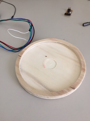
2. I then measured the Stepper cog to make a pocket cut the correct size in center the center of gear and rested my stepper motor cog down in it.
3. I filled the mold with plastic
4. And let it harden around the cog.
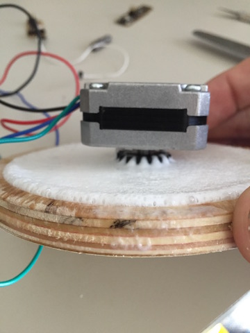
5. When I put in a peg my stepper was ready to be installed.
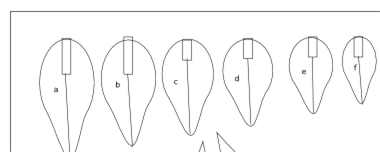
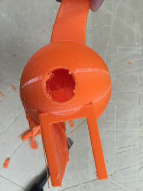
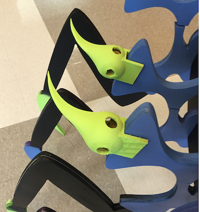
3-d Printed Fin Spikes
From the concept drawing I wanted each fin capped with a spike.
I decided that I wanted to 3-d print them so I turned to Fab Academy Files Week 5, 3-d Scanning and printing.
I selected Autodesk Fusion 360 as my platform to create the spikes and the STL files to 3D print.
I created the shape using simple primatives, the combine function, and sketch.
More Organic Spike by rfletch on Sketchfab
The STL files can be found here Final Project fusion360 .STL files.
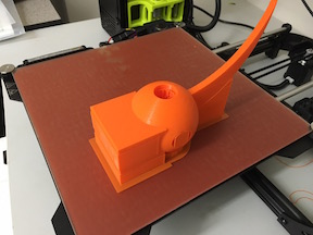
I then loaded up the .STL files and printed them on our
Taz 3D printer.Printing on the Taz was awesome. I chose the standard time and to build scaffolding around them, so there was less chance of failure. The total time for each spike took almost 10 hours. Because I wanted 12 of them, this was a problem. Time was running out. I ended up printing about 5 of them and they can be seen below.
Spike Printing
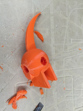
I then painted the spikes an alien green and put them on ths sculpture.
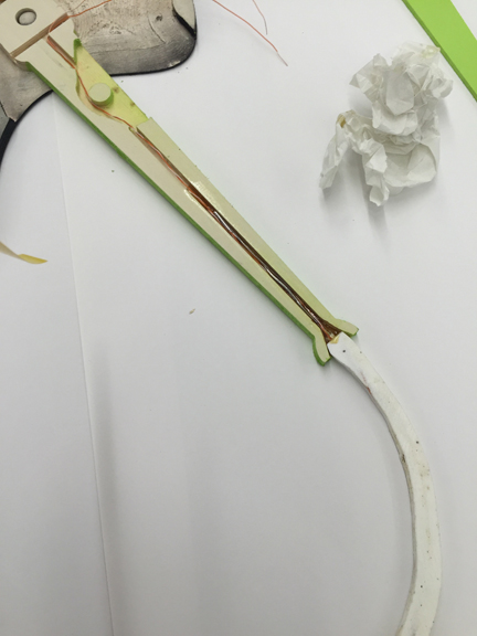
Laser Cut Lure Rods
I used the laser cutter to make the rod that would drive the lure movement like a piston, as can be seen below.
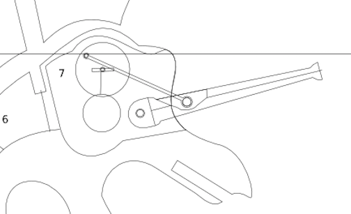
and in close up here.
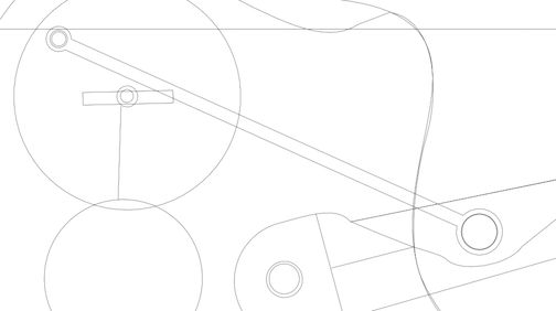
Here is a picture of the .PDF I laser cut.
And a video of it driving a the lure wheel.
The sculpture was now ready to assemble, but the final product can be found here.
Pressfit Sculpture Final Result