The brief for this weeks
assignment was to design something small that would be
difficult to machine any other way (using subtractive
manufacturing methods) that can be 3D printed. I chose to do a
simple design of a dice using Google Sketch-Up. I have been 3D
modelling for many years now and I am trained in Catia and
Solidworks but this was a nice way of making a commonly
recognisable part using freeware software.
The design itself (although simple) does use many of the
common design features that Sketch-Up offers including
push-pull, dimensioning, creating pattern features, scaling,
and accurate positioning using guides. I have used this
exercise in the past with inexperienced 3D modellers and it is
a good way to get to grips with the way that Sketch-up works,
and how to use shortcuts to model efficiently. In short there
are many different ways that you can arrive at a resultant
object using 3D modelling, and some are more efficient than
others. The key is to experiment and learn the best practice
for modelling objects. When considering best practice it is
often necessary to use a more advanced program that has
hierarchical and parametric deign capabilities that Sketch-Up
does not have but for this exercise Sketch-up worked very
well.
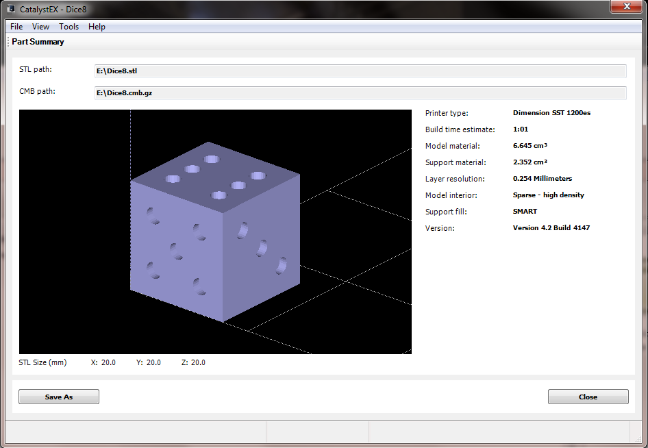
Here is the model I created.
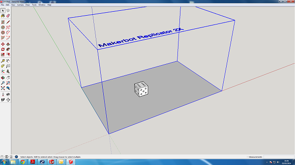
Although it would be possible to machine this part from a
block it would require either a multi-axis machine to be able
to complete the part in 1/2 toolpaths which are not available
in most Fab Lab's s or alternatively you would need to create
a jig (to anchor and keep relative dimensions) and accurately
rotate the part and machine each side individually. For this
reason I think the design fits the brief quite well.
3D
Printing - UltiMaker 1
At Fab Lab Manchester we have access to two 3D printers, so to
make the most of the assignment I thought it would be a good
idea to print the same part on both printers and compare the
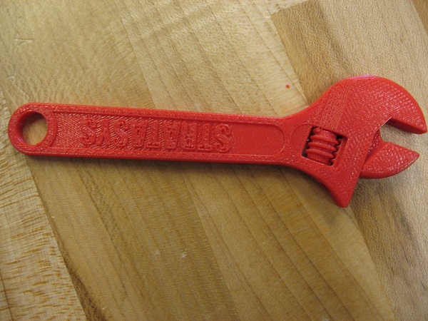
results. This is an interesting comparison as the UltiMaker 1
costs 1/30th the price of the Stratysis Dimension 1200es and
on paper has 5 X the layer resolution of the more expensive
machine. Both use FDM
(fuse-deposition-modelling) technology to extrude plastic
filament and build parts in stacks of cross-sectional layers
but the obvious main differences are that the Stratysis has
dual extrusion and uses a soluble support material to help
build more complex shaped parts and even assemblies of parts
printed all in one go (ready assembled).
The second main difference is that the Stratysis has a
patented closed and heated building environment. This extra
control of the rate of cooling in the material should allow
for a more consistent and repeatable build quality of parts.
The last difference in the test to be aware of is that the
UltiMakr can extrude PLA
(poly-lactic acid) a plastic with green credentials which is
made up of plant/vegetable protein or ABS, a substantially
less green plastic which is not bio-degradable and has
structural properties more akin to an injection moulded part.
In this test the UltiMakr used 2.85mm PLA Filament which costs
aprox £30 per kiogram. Whereas the Stratysis extruded ABS+
plastic at a cost of £160 per kilo (through a company that has
reverse engineered the material called Bolson Materials.
Cartridges direct from the seller cost £250 ex vat and come
equipped with a micro-chip that makes it very difficult to
hack the cartridges to accept refills of cheaper fialment
material- although
it is possible.
Results
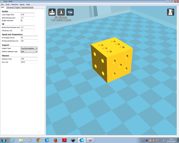
- Ultimaker 1
Print time: 22 mins
Layer Resolution: 0.25mm (this is the
lowest layer resolution available and was chosen to match
the stratysis)
Support Material method: Buildplate support
Fill density -
50%
Build Accuracy: 19.78 mm from a 20mm Dice = 98.9%
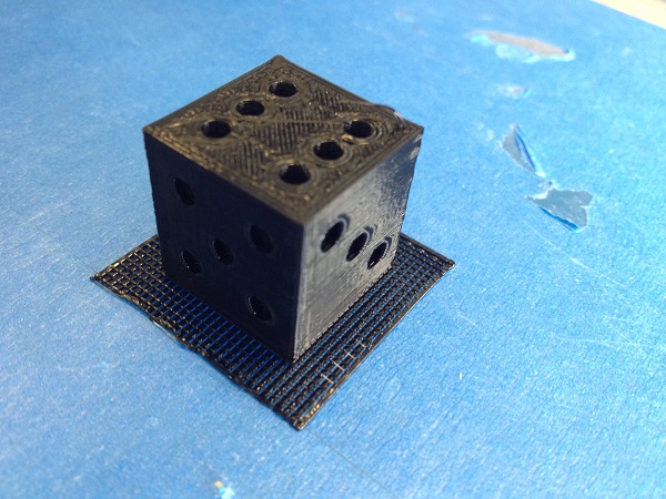
Observations
- Ultimaker 1
Surface finish - Good on all sides apart from the bottom
of the dice (buildplate side).
Support Areas - When creating the recess for each number on
the side there are strands of support material which need
removing. As s tehsupport is built using the same material
there is strong adhesion to the model and it is necessary to
cut away these areas with sharp snips as oppose to trying to
break away the support.If you try to pull away the support
sections they often damage the model section.
Layer resolution / texture - It appears to have quiet a finely
packed layer resolution with no major defects.
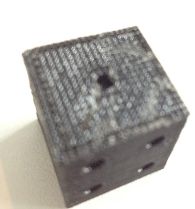
Results
- Stratysis 1200es
Print time: 1h 14 mins
Layer Resolution: 0.25mm (this is the
highest layer resolution available)
Support Material method: SMART support
Fill density -
High density
Build Accuracy: 20.20 mm from a 20mm Dice = 99.0%
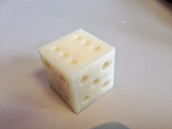
Observations
- Stratysis 1200es
Surface finish - Uniform
on all sides.
Support Areas - Support material was calculated using the
Catalyst 4.2 software suite which is supplied with the
printer. SMART support is the most used of all 4 types of
selectable support and this was used for this model. SMART
allows the software to decide where t is necessary to build
support for the best part in the defined orientation. It is
possible to choose Basic/Breakaway support options but this
was not chosen for this experiment.
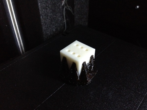
Support encased approx 50% of the model and therefore it was
necessary to dissolve the material in the bath of heavily
diluted sodium hydrozide solution which is heated to 70
degrees C and pumped around inside the tank. This process took
over-night to completely remove the support material from the
dice (although using a fresher solution, it would be closer to
3-4 hours).
Layer resolution /
texture - The dice from the stratysis appears to have a very
neat finish. The texture looks uniform throught the model
and at the edges (seams) there is a sharp clean edge.
Conclusion
When looking at the results the two machines performed very
well and also very similarly in terms of build accuracy on
the overall size measurement, in fact it could be said they
performed exactly as expected. The Ultimaker was quite easy
to set up using Cura and it was easy to find/change all
necessary parameters before sending the job to the printer.
But the machine itself did need a few more checks to ensure
proper extrusion was occuring before printing the part. It
quickly produced a dice to a good standard and although the
removal of buildplate support left a poor underside finish
it still made for a very usable part. On the other hand the
Stratysis had a full automated software setup which requires
no machine checks/calibration (in between 3 monthly checks
and maintenance). The software is clear and easy to use. The
printer takes it's time to print the dice in 1 h 14 mins,
and a lot of this time is due to the use of support material
on the build. The dual nozzled head has to clean off and
select the new nozzle drive at least once for each layer,
this explains the big difference in time. Despite the time
(we all know 3d printing is a slow process) the part was
built very successfully and with the use of soluble support
I was able to get an excellent surface finish on each side
of the part.
I was surprised when I took the measurements of the dice and
found they were almost exactly the same level of accuracy.
As I have worked in the lab for a few years now I am aware
of the strengths of each machine and I think that the test
didn't accurately show these. From experience I know that
the stratysis (although expensive, and slow) produces
consistent parts time after time and when used for
prototyping 2 interacting parts I know that in the design
process if i leave 0.5mm difference between the interacting
sections it will fit together correctly almost every time.
In contrast to that when I have designed parts for the
Ultimaker i have often had to open out holes by as much as
1.5mm to make them fit on a particular tool/part and the
offset value has never really been constant. It is with this
experience that I think if I were to print 10 dice and
compare each one that the Stratysis' quality would show
through. Also I were to set-up a pack of dice in different
bed locations that would move the printer around more than a
20mm X 20mm square I suspect that the errors would start to
mount up on the Ultimaker.
3D
Scanning
Due to time constraints we decided as a group to work
through each scanning method available as a team and then
each write up a different process.
Modella
After working through using the Modella tactile scanning
feature with the Dr Picza software James
wrote up that method of scanning. For me it seemed
that the Modella although outdated in its tactile scanning
system and without the option of getting a fully 3D scan (as
it does not get overhang data and it does not map any data
for the bottom face/s of the model) on the plus side it does
very good resolution and with the use of the high resolution
3 axis movement it does make for a very detailed and
accurate point cloud.
123D Catch
Having used this method before in the past with quite
poor results I was keen to improve on them and see how other
people obtain good scans using this system. After doing some
research I found that the important parts of getting a
good scan were to:
- Take at least 40
photos showing top bottom and side viewpoints
- Use a detailed
background such as a newspaper page that has different
data points to help the software stitch together the
photos correctly
- Take photos from
the same distance away from the model each time and
don't use a flash as shadows will be included in the
resulting mesh.
- Don't use
auto-focus feature on a camera as this can blur
important data in the image and skew the resulting scan.
It occurred to me that a jig could be constructed to try and
keep constant the viewpoint and field of vision and could
work with a controllable turntable to get the best results.
This may be something I look to construct in machine week.
As a team Annie
chose to write up this scanning method. Annie
investigated this method but it seems to me that it can be
reasonably successful when scanning larger objects but
smaller objects with finer detail seem harder to scan and
more prone to error.
FabScan
FabScan is an open-source, do it yourself 3D laser scanner
which started out as a bachelor's thesis by Francis
Engelmann, supervised by Rene Bohne.
David
our mentor at the lab has put this machine together as part
of his coursework when completing the academy in a previous
year and it has been tinkered with recently
and is now scanning data.
To use
the machine we installed fabscan control software on David's
mac connected up the webcam and Arduino controlled
turntable.
My first
thought was to try and use this machine to scan the dice I
had printed on the Ultimaker (as the Stratysis model was
still dissolving at the time) and then I could compare the
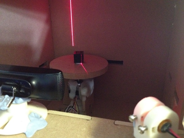
scanned data to the original design. Unfortunately after
configuring the scanner which involves adjusting the field
of vision of the webcam and ensuring that the laser projects
a vertical line across the centre of the turntable and does
not light up the front face of the turntable or the ceiling
of the FabScan box, it became clear that scanning a black
plastic dice in a dark box was not going to give good scan
data.
As this
wasn't proving successful I then tried to scan the same
object that we used for the Modella scanning - a metal
pencil sharpener. After setting up and starting the scan it
again became obvious that the scan was not producing good
data. A reason for this could be the reflective surface of
the object diverting the laser and not being picked up
accurately by the webcam.
In an effort to get a good
scan from the FabScan I choose to scan a larger less
reflective object - a red chocolate box. When setting up the
FabScan there is the option to use poor/normal/best scanning
options. These options seem to vary the amount of points of
data scanned by modifying the amount of degrees turned at
each scan point. I chose best and scanned the chocolate box
and got this result.
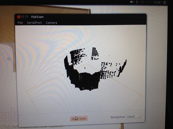
This data shows an error that was soon explained when i
heard a thud and lifted off teh cardboard to reveal
this....
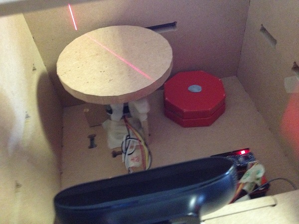
The lesson here is to make sure your object is held
down securely to teh turntable. So after some searching aroung
teh lab and trying out some tape i desided more Blutack was
the way to go.
The next scan was
successful and the data was exported as an .stl and a .pcd.
This is where another error was made. After trying to open the
stl file it is obvious that The stl export has not been
successfull as the file does not open in any program without
returning an error and after looking at the size of the file
it is only 27 bytes. This being
the case I next tried to find a file that opens or converts
.pcd files which is where I came up short. It seems that
MeshLab will open .pcl files which are an export option but
did not save from my scan. Therefore it seems I need to rescan
and re-export that data to analyse it with MeshLab. This was
not possible in the time for this week and I will re-visit
when possible in the next week.
Downloadable
Files
Sketch Up model - Dice
Scan Data -
chocolate box.pcd