Making circuit boards,
soldering of electronic components onto the circuit board to
create a FABISP in-circuit programmer and finally programming.
We used the milling machine Roland Modela to make the traces and
cut the outline of the board.
Steps
to mill the board on the Roland Modela – workflow
Fix
board to the Modela
To set up the Modela we first
protected the bed with a sacrificial board. Ensure the surface
is flat and clean then add double-sided tape to the back across
full width of your
copper clad FR1 PCB board to hold it firm while milling. Leave a
bit of tape overhanging the board to help removal.
We choose to build the crystal
based version in our Fablab.
Open terminal type password
fab
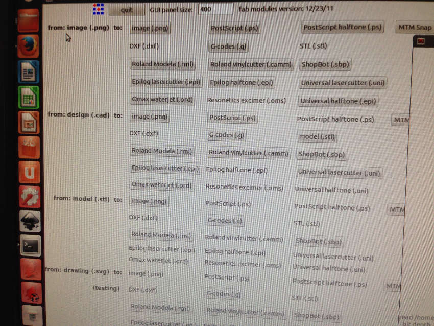
Fab module opens
Choose image (.png) then
Roland Modela (.rml) see photo below
I
followed these steps to set up the modela software
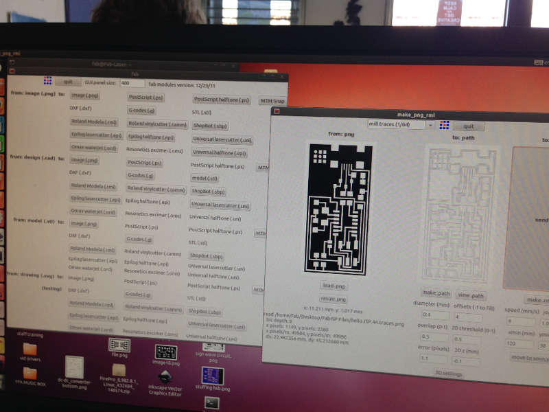
Load .png file – for
Roland Modela (.rml) find on desktop in FabISP Files/hello IS
p.44.traces.png
Select the type of job – mill
traces (1/64) the pre selected defaults for cutting PCB traces
based on using a 1/64 inch end mill bit.
Select make path
Set the x,y,z origin
Set x,y use the move button,
measure distance required and set the origin
Set z origin (the distance the
bit will travel down when milling) by moving the bed up
setting the bit in correct position then carefully lowering it
so it touches the board. Check bit is secure
When origins are set make an
rml file
Guard back in place and send
to machine.
Traces take about 10mins to
mill.
When finished press view to
see board and use vacum cleaner to tidy up
To cut out the board
Change bit to a 1/32 inch
Download ISP.44interior to cut
out board
Make path
Set x/y and then z by first
centring the bit in middle of board
Make.rml
Guard back on
Send it
Remove the board with care as
it’s easy to damage the delicate copper which I did on my second
board.
Gently de-bur with a steel
ruler and wash with soap and water to remove residue then we are
ready for stuffing the board.

Some of the problems I encountered
Ensure the surface is flat and
clean before securing your board. I had this problem with my
first board, the traces cut deep one end and not at all the
other! I started again. We changed the 1/64 bit as well due to
the cutting problems I encountered. Another problem I
encountered which was tricky to sort out was the shim/wedge for
the cover interlock switch that the modela uses to detect safety
cover is in place. It had worked loose and the modela refused to
move! It took sometime to work out the problem.
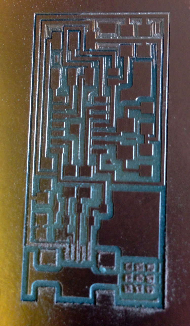
Picture of my first
board below, traces deep one end and no traces cut the other end
Soldering
the board
Soldering was completely new
to me so it’s been a steep learning curve and I have had to
practice lots before starting the final board. I started with
the smaller components as recommended but then leaving the USB
to last was very stressful as it proved to be so tricky. I found
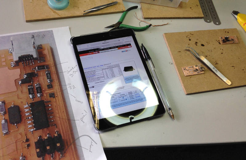
work flow was very important laying out a copy of the Eagle
board file next to me with an ipad to look up component
identity.
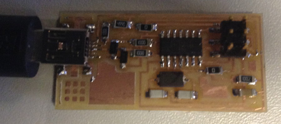
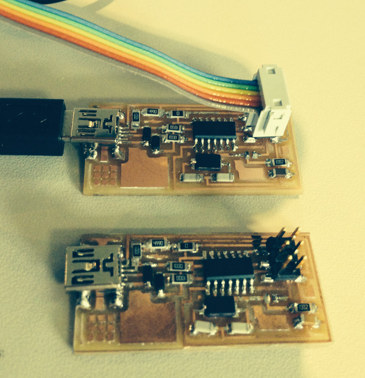
Smoke Test went well, no smoke!
Programming
the board
Having
installed the software for AVR programming I followed the Fab
Academy at AS220
FAB ISP Tutorial which was very helpful, thank you. All went
well with the
programming but when I later came to use it to programme other
boards I got
error messages. After much trouble shooting and advice it turns
out the board
was fine when I put back one of the 0 ohm connectors to power
the board.
I now have 2 boards working, so exciting! I've learnt
alot this week, particularly trouble shooting FAB ISP boards.