 Fletch's Fab Academy 2014 Blog
08. Embedded Programming
This weeks task was to read and understand the datasheet for the
ATTiny44 microcontroller on our 'Hello World' boards that we made
the other week and then to program the board to do something
interesting using as many languages and programming anvironments as
possible. My background covers a lot of embedded programming
and I've used ARM and PIC microcontrollers before for lots of
comercial projects. So, rather than try to use as many
languages as possible I decided to change my task slightly and
improve my understanding of what is to me a new microcontroller
family by trying to flex as many of the features of the ATTiny as
possible.
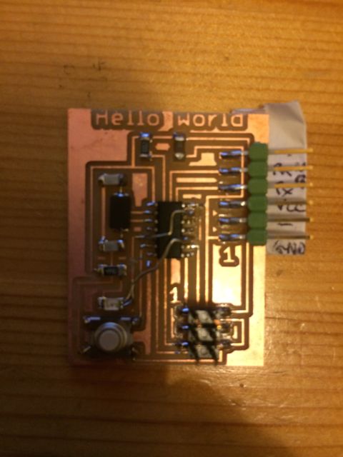
08.01 Board Definition
Before starting I needed to know the definition / IO pin usage of
what was actually on my 'Hello World' board as follows:
- PA0: Tx (labeled from the point of view of the PC talking to
the board, actually data into ATTiny)
- PA1: Rx (labeled from the point of view of the PC talking to
the board, actually data out of ATTiny)
- PA7: Switch input (Switch connects to GND, will need to turn
on internal pull up)
- PB2: LED output (LED is connected to VCC via current limit,
set PB2 low to turn on LED)
08.02 Software Tool Chain
I chose to use 'Crosspack AVR' on the Mac as my gcc tool
chain. I aslo already have XCode installed and as Crosspack
creates blank XCode project templates I decided to use XCode as my
developement IDE.
To create a new project in your developement folder type:
avr-project projectname from a terminal window. This
will create a blank project template with a main.c and a
makefile.
Next you will need to edit the makefile to set the DEVICE, CLOCK,
FUSES and PROGRAMMER correctly as follows:
DEVICE = attiny44
CLOCK = 20000000
PROGRAMMER = -c usbtiny
OBJECTS = main.o
FUSES = -U hfuse:w:0xdf:m -U
lfuse:w:0xff:m -U efuse:w:0xff:m
Then just fill main.c with code, glorious, code...
I may revert to Textmate or Eclipse as an IDE as I'm not completely
happy with some of XCode's features.
08.03 Initial Blink Test
I actually performed this test the other week after building the
board as I wanted to know that it worked. The code (here) blinks the LED
until the switch is pressed, at which point it keeps the LED
on. The code's not pretty but it was a quick and dirty test to
show that:
- My tool chain worked
- My basic understanding of the ATTiny IO port programming was
OK
- My FABISP worked
- My Hello World board layout was what I expected
- My Hello World board had been manufactured OK
The one thing that it didn't test was the serial port.
08.04 Basic Serial Port Test
So the next thing I wanted to check was that the serial port worked
OK. For this I simply used the code that Neil linked from this
weeks class page (non-irq
and irq
based). Initially this didn't work, I could send
characters but not receive them. I tested another students
Hello World board and that was OK. On inspection of my board I
discovered that the 'Tx' pin on the ATTiny wasn't quite soldered
down correctly. A quick re-heat with the soldering iron and my
board worked OK.
On inspection of Neils IRQ based serial code I wasn't happy with it
as it's not truly IRQ based. It uses an IRQ to detect he start
of an received character, but then the actual reception and
transmission processes are blocking. Serial data tx/rx (even
at 115200 baud) is a slow process in terms of the number of CPU
instructions that could be run whilst a single character is being
sent on the serial line. So this blocking actually stalls the
CPU for a significant time. This is OK for a simple test, but
not very practical if any 'real time' work needs to be done.
08.05 Test Signature Bytes and EEPROM
Now that I had working serial communications I extended theh test
silghtly in two ways. Firstly to read the device signature
bytes so that I could see that the device actually reported itself
as an ATTiny44a.
Then secondly, to read and write the EEPROM on the device. I
did a simple test that performed the following actions each time the
device booted up:
- Read address 0 from EEPROM and print it out via serial port.
- Increment value by 1 and write back to EEPROM address 0.
This gave me a very simple incrementing 'boot count' telling me how
many times the device had been powered on. For a real
commercial product a there are two issues with this:
- The EEPROM value is never initialised, I start counting from
what ever value is in the EEPROM at the end of the manufacturing
process. Appears to be 0xFF.
- There is no corruption check. A CRC or checksum needs to
be added. This would also allow for initialisation of a
new device as it would fail the CRC.
Code for the above tests is here.
08.06 Improved Serial Code
I decided that I'd like to have a proper IRQ base impementation of a
software UART. I thought that someone will already have
implemented it, and when I looked around I found this application
note from Atmel that describes exactly what I want,
AVR304: Half Duplex Interrupt Driven Software UART
AVR304 Half Duplex
Interrupt Driven Software UART. However once I
downloaded the code and inspected it the existing examples only
support the ATMega range of microcontrollers. The code is also
written for Atmel Studio which has slightly different sets of
compiler directives for things specific to the Atmel
processors. So I decided to port the code over the the
ATTiny44 and the gcc toolchain.
- Read the application note and it's associated code to
understand what's going on.
- Read the ATMega48 and the ATTiny44 data sheets in tandem to
understand any differences in the parts of the microcontroller
that are used.
- Read the AVR-LibC
and Crosspack User Manuals to understand the differences in the
compiler directives.
The code in AVR304 requires one 8bit timer (Timer0) and one external
interrupt (INT0). These resources exist on the ATTiny44,
however our serial port is wired to the wrong pins on the
chip! We need the serial data in (Tx) to be connected to the
INT0 pin in order to be able to use it's edge detect based IRQ
functionality correctly, the level change IRQ functionality of the
PCINTx pins isn't good enough as we can't specify IRQ's based on
only rising or falling edges. It could be fudged together by
checking the pin state after the IRQ is generated, but as the
correct pins are actually available I decided to re-work my Hello
World board slightly. I decided to modify the board definition
as follows:
- PA0: Tx (labeled from the point of view of the PC talking to
the board, actually data into ATTiny), not used any more but
leave Tx connected here as it has no effect.
- PB2: Tx, this is the INT0 pin so I've connected Tx here also.
- PA1: Rx (labeled from the point of view of the PC talking to
the board, actually data out of ATTiny)
- PA7: Switch input (Switch connects to GND, will need to turn
on internal pull up)
- PA3: LED output (LED is connected to VCC via current limit,
set PB2 low to turn on LED)
- I've disconnected the LED from PB2 by cutting the
track.
- I've re-connected the LED to PA3 with a wire llink.
- Then I've connected PA0 to PB2 to route the Tx signal to both
pins, PA0 isn't needed any longer but it was easier to leave it
connected.
I used the legs of old through hole resistors for the re-work.
After this re-work I re-tested both my old serial code (with changes
for new pins) and re-tested the Blink test code. Both worked
OK.
I've ported most of the serial code and in essence it works
OK. Some tweeks are needed based on the actual processor
resources available. Code is here.
08.0X Game
I'd like to push things to see if I can actually write a game using
just one button and one LED. I think that either of the
following should be possible:
- A 'Simple Simon' type game where the device blinks and LED in
a rhythmic pattern that the user has to remember and then
repeat.
- A reaction timer game where the user presses the button as
fast as possible when the LED comes on.
For both of the above the serial port can be used to print out high
scores stored in EEPROM. A simple menu system could also be
implemented on the serial port allowing the user to select which
game they want to play.
ToDo:
Re draw Eagle schematic to reflect re-works on board.