 Fletch's Fab Academy 2014 Blog
07. Computer Controlled Machining
This weeks assignment is to 'Make Something Big' on the
shopbot. So we have available a 3-axis CNC milling machine
with an 8 foot by 4 foot bed and as much 12mm plywood as I
need. As I'd designed my press fit 'Castle Construction Kit'
from week 3 parametrically I decided to simply scale it up for this
weeks task, so I'm aiming for a castle construction kit that a 5
year old could use as a playhouse.
07.01 Design Tests.
My first task was to get to grips with the tools and workflow for
using the shopbot. So I used this as an opportunity to do a
couple of design tests of joints hinges and sizing.
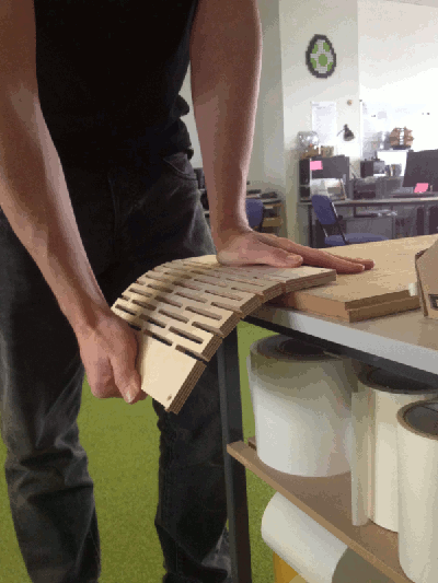
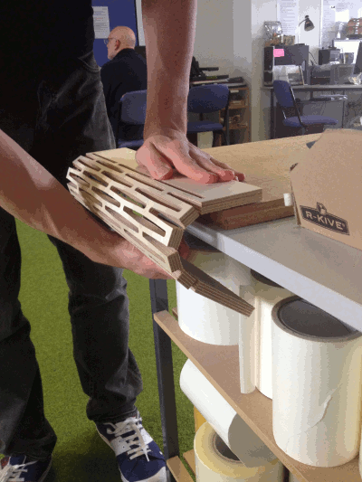
07.01.1 Hinge Test
One of my fellow students was testing a hinge design on the shopbot
for his project. The initial test was very stiff and had less
flex than he had expected. As I wanted hinges to allow my
castle towers to wrap around into shape, I decided to examine the
design, try to understand what was wrong and then improve it.
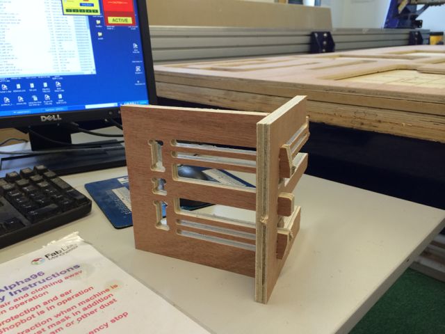
Below is a picture of my improved hinge design marked to show where
the flex in the hinge comes from.
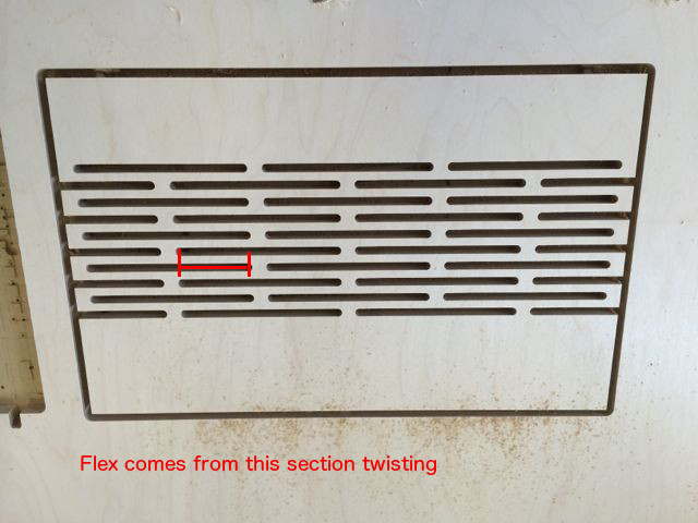
By maximising the length of the section marked in red you can
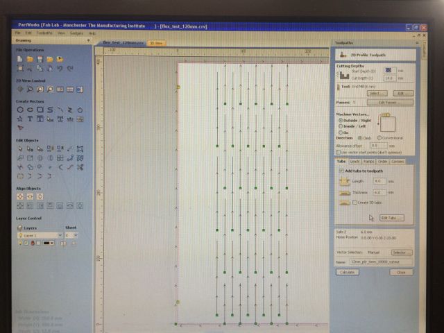
maximise the flexability of the hinge. I designed this test
part completely in 'Partworks3.5' as a test of this tool path as the
rest of my design was in kokopelli. CRV file here.
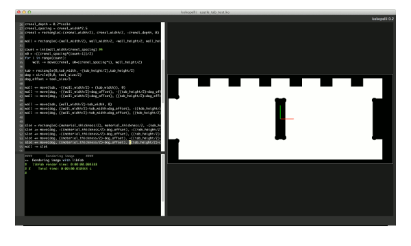
07.01.2 Koko Toolpath Test / Scale Test
Moving on from this I decided to do a quick test in kokopelli.
I wanted to see what the work flow was to get the files from
kokopelli onto the shopbot and check what scale my final part would
come out at.
I would like to test using the CAM panel direct from kokopelli,
however our shopbot computer doesn't currently have fab modules or
kokopelli installed, I've started to rectify this, but more time is
required to get Ubuntu updated to a suitably current version.
I also want to test Neils prefered method of CAD->PNG->Shopbot
vai fab modules. My kokopeli test file is here.
- So I decided to export my files from kokopelli into Partworks
and go from there.
- I exported to svg from kokopelli. Resolution default of
10 pixels/mm.
- I imported the svg into Inkscape.
- Export from Inkscape as a pdf with no modifications.
- Open this PDF in Partworks.
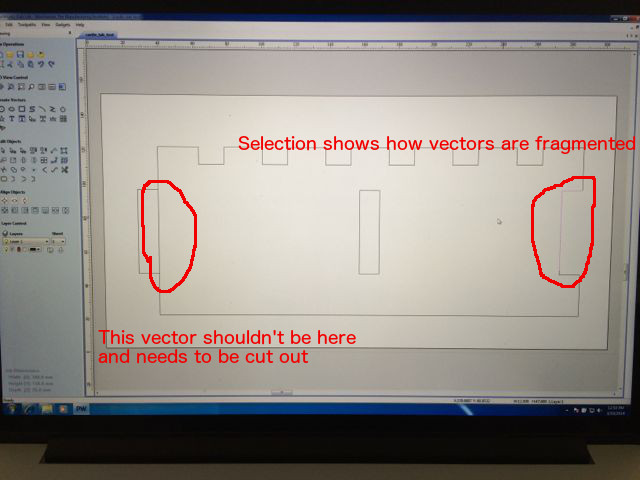
Once in Partworks I noticed that the vectors in this file were
'fragmented' into smaller sections and that I had some extra vectors
across tabs etc that I needed to delete manually. I created
the tool paths as before but when I previewd the part some vectors
in the origional design were not being cut. I had to add
another step and 'join' all of the vecotrs into one continuous loop
once I had imported the PDF into Partworks to fix this.
It took a couple of iterations to make sure that I had the scale
factors correct and that the part was going to come out at a
sensible test size. Once I was happy with this I cut two
copies on the shopbot.
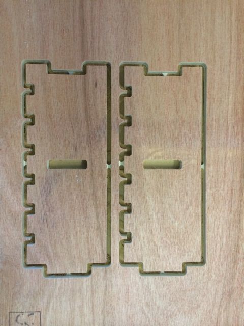
My first test part was to check scales and tolerances of the end
tabs, so it had no dog bones on internal corners and the joints
(particularly the center slot) wouldn't work.
07.01.2 Joint Test
So I went back to kokopelli, added dog bones, and re-cut to test the
joints. I could have added these dog bones manually in
Partworks. However I wanted to reduce the number of additional
manual operations required in each design itteration, so I made them
part of the kokopelli design.
The external / internal dimensions of the tabs work OK, but I'd like
to cut a series of test slots to correctly gauge the tolerances
required for a good interferance fit. I also noted that my
12mm ply was actually only 10.8mm thick.
07.02.3 Joint Test 2
I then moved on to creating a variant of the MTM snap joint in 10mm
ply. This uses the same design file as
week 3 'Press fit kit', just set the machine type to 'shopbot'.
This joint works, but in order to get the flexibility required the
'tangs' need to be longer than in the 3mm ply version. Also
the 10mm ply used is lower quality than our 3mm ply. It's full
of discontinuities in the internal material layers that create weak
spots. This joint design regularly snaps in this material.
07.03 Cut Real Thing
Again the same design file
was used as week 3 'Press fit' but with the machine type changed.
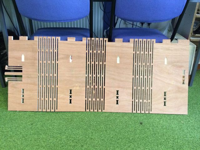
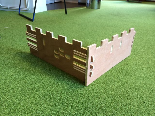
Above left - tower section before assembly. Above right - wall
sections.
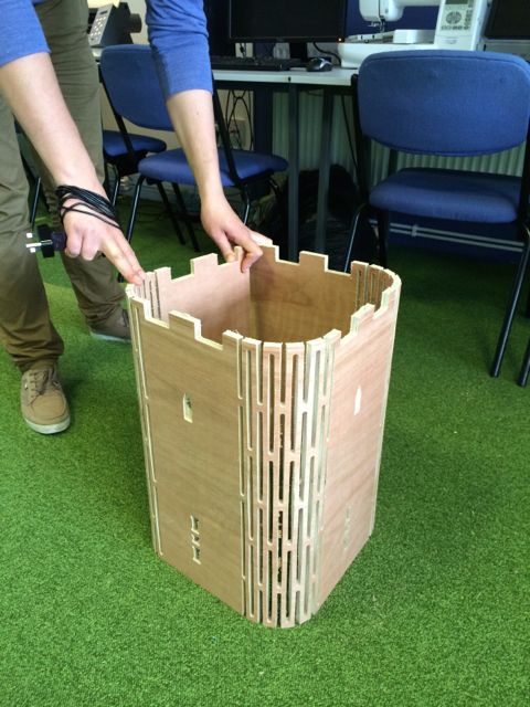
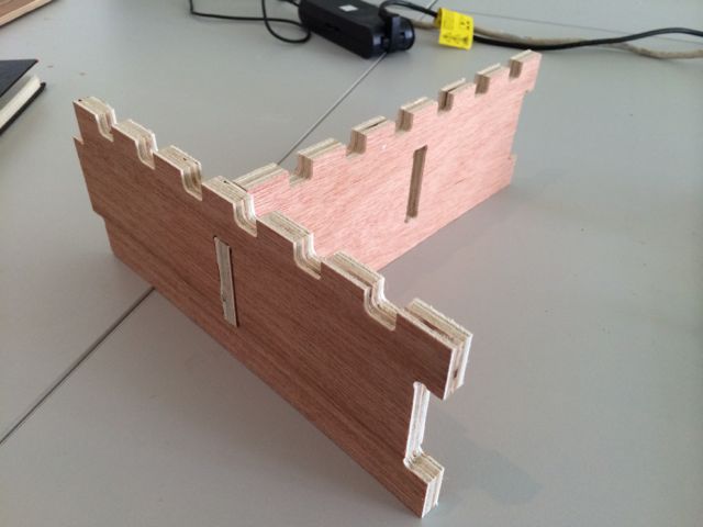
Above - tower section folded into shape.
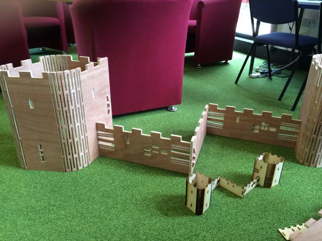
Above - The big and little versions of the castle together.
Further Unordered Thoughs...
Cut a 3D profile in foam, to test the 3D tool paths.
Try one in thicker laminated wood?
Fab modules and Kokopelli onto shopbot PC or drive shopbot direct
from my mac.
Test CAD->PNG->Shopbot vai fab modules.
Tabs are great, you can easily remove them with a craft knife.
Test cut with different slot sizes. Koko export error...
Test cuts with 6mm down cut and 0.25inch compression cut
compression:
no space to ramp in?
tool gets very hot and whilst no problem do get
'burning smell', also cut surfaces are 'blackened'. Tool
blunt?
really glowing embers, see photo, so stopped job. turns
out speeds and feeds for tool into tooldb were wrong! Tool
going too slow!
corrected and cuts really quick and well.
measured with calipers:
test tab cut with 6mm down cut 50.1mm
test tab cut with 0.25inch compressiion 51.5mm, even though
tool size was correct. Surface internal to material is much
rougher!