Abstract
This week was about having a large view of the final project, defining its scope and a plan.
Some of the question raised were:
- What do I have at disposal for my project?
- What do I have to learn?
- Where do I start?
- How do I catch up my backlog?
I brainstormed a lot
My biggest achievement:
My biggest struggle:: Catching up several weeks
Missing material
Chronology
| Thursday | Friday | Monday | Tuesday | |
|---|---|---|---|---|
| Catching up | Inventory | Catching up | Management training | |
| Wifi board debugging | Group project by myself |
Setup
| Softwares | Fonction |
|---|---|
Skills acquired
Asssesment validation
What will it do
My project will harvest the mechanical energy of walking and hopefully use it to power a Wifi board.
It will be a sensitive tile. As opposed to today "spy" sensors, the sensing will be made visible through deformation.
First I will measure the voltage produced. In future developments some other parameters could be measured, this is why I will equip my board with SCA/SCL pins .
More info are available on the project page.
What has been done before
Along the 16 weeks I made some bricks for my project:
- Week 1 I explained < a href="http://archive.fabacademy.org/archives/2017/woma/students/1/Week12.html#tab4">my first ideas, among them the energy harvesting tiles
- Week 7 helped me think of a mutipurpose design, the hexagonal structure will also be the framework of my pavement
- Week 12's addition to the final project here
In brief Week 12 helped me to think of a sole, I made a proposition of how to focus force on smaller surfaces through insertion in silicon
- Week 13's addition to the final project < a ref="http://archive.fabacademy.org/archives/2017/woma/students/1/Week13.html#tab4">here
In brief I tried to build a capacitive sensor to place below the sole
- Week 15's addition to the final project < a href="http://archive.fabacademy.org/archives/2017/woma/students/1/Week15.html#tab4">here
In brief I build an autonomous Wifi board with input and output
Where the materials will come from
I reviewed what was left for the final project: - electronics components(accelerometer, phototransistor, thermistor, mosfet, potentiometer trimer, female/male pins, resonators, crystals, right-angled male pins, usb plug, Attiny44/45, ATMega, led, resistor, condensator) - electronics tools (soldering station, flux, solder, fume vaccum, third hand, clamp) - PCB boards (less than 10) - no composite resin - some mold resin - no wax mold - a little bit of plaster - scrap wood - maybe a plank left from the "make something big" week - 3D filaments (details to come) - scrap cardboard, cork
What we have the most is probably electronics components.
We learned to use all the digital equipements at WoMa, except maybe the 6-axis robot they are renting. Yessine paid an extra training to do so.
Last week with Thomas we met with Volumes Fabmanager who showed us their tools (big CNC, 3D printer, woodwork space...). The Fabmanager -actually one of the 3- told us that he initially wanted to be involved in the FabAcademy but finally the Master Design by data got all his attention. He nicely invited us to use their tools for our final project if needed. I plan to do so because I believe it is part of the curriculum to get familiar with different Fablabs and tool brands. I really would like to test the CNC as it is using automatical mesh changing. Otherwise we are familiar with all the tools they are using.
I asked Guillaume Attal for a visit of Villette Makerz, a fresh new node for the Fabricademy. He kindly invited us for a tour-and a beer on their amazing rooftop- on Friday. I sadly forgot to take pictures. He showed us their complet set of equipements: laser cutter, 3d printers, digital embroiderer, ceramic oven, thermoforming machine. I was impressed. I did not spot CNC -small nor big- though. He invited us to get a membership, he even agreed on a FabAcademy discount. If we want to learn to use the embroiderer or the thermoforming machine we would need to pay for a training and some hours. During the tour Guillaume gave me two reference of device he thought I could use to harnest energy:
a pressure sentitive sheet,
a pearltree page on conductive fabrics
After this small tour I thought it might be interesting to open complementary labs to the FabAcademy, this might also help to split the financial burden.
I would also have loved to introduce advanced material as the one Carbon3D showed use. I recently read about a new energy harvesting material FENG. Also the CubeSat Neil's told us about are made with a special filament, the PEEK filament.
Based on those inventories, I will need to add:
- wax for molding
- supercapacitors
- ESP8266
- piezo
- solenoid
- copper wire
- copper tape
I will try to keep the price as low as possible.
Electronics BOM
Here is a revision of this list I gave to Alex WoMa to see if we could order it with remaining fund-if there was any-. All will be purchased online to Digikey a Franch provider.
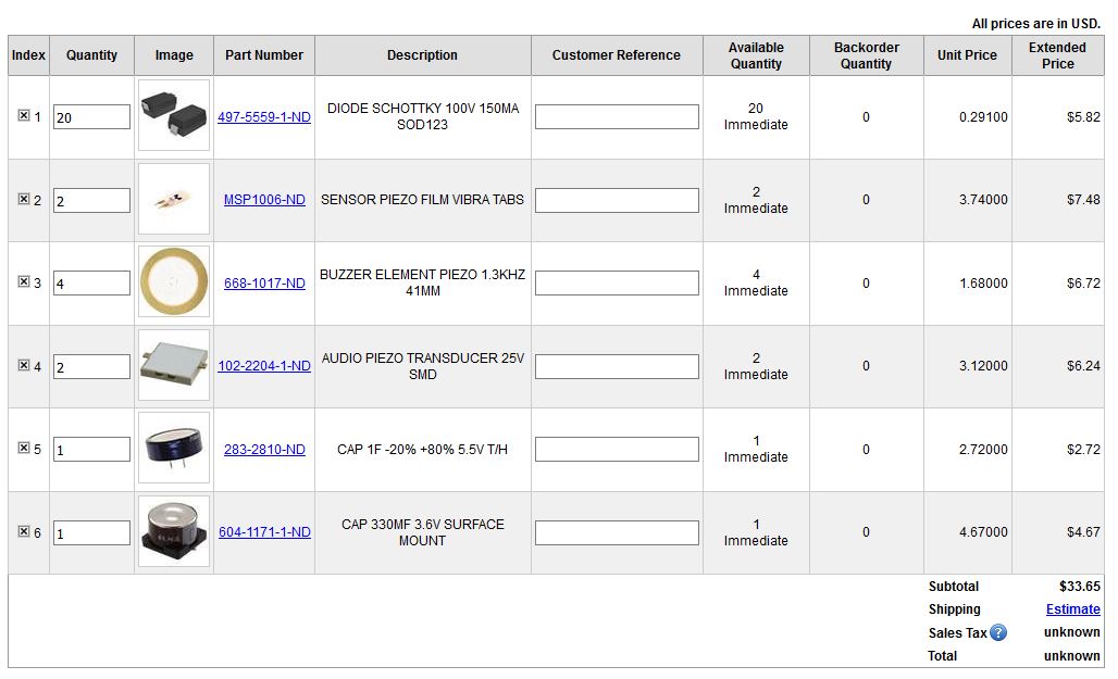
electronics cart
Those are the components I need to test the piezo harvesting and the energy storage. I ordered different type of piezo (diaphragms, strip, SMD) as well as supercapacitors (with 2 different capacitances). Schottky diode are needed for rectifiers. For the moment I didn't order something to test solenoids or Peltier. They could be added in a second time. At the moment the bill is up to 33 dollars, just for the test part. I will be careful not to raise too much above.
To this list I would have to add multiple ESP8266 and maybe Zener diods to switch energy source.
BOM
A few weeks later I came with a more accurate BOM. It ended up being really different from the predictive one. Here it is:
Structure
- 1/4 plank poplar [20 euros]
- 30" CNC machine time
Covering
- 700ml silicon mix [20 euros]
- 3 medium planks 80x60 [20 euros]
- screws
- 30" laser cutter time
Electronical
- 1 PCB sheet
- 1 ESP8266 [3 euros]
- 4 Schottky diodes [1 euros]
- Connectors (6+8+8 female, 6+8+8 male, 2x2)
- 1 button [few cents]
- 3 resistors (1MOhm, 10MOhms, 1 kOhm)
- 1 10microF capacitor
- 6 piezo diaphragms [10 euros]
- Wires
- Tape
- 1 hour CNC machine
- 2 hour soldering
Interface
- Register on Blynk
- 30" flashing/programming
Mechanical
- PLA 1/8 of a reel [10 euros]
- 10 hours of 3D printer time
- 1/4 of a medium plank (80x60)
- 15" laser cutter
- 6 compression springs (1.4 cm diameter) [10 euros]
Integration
- Rubber band
- Pushpin
Total
Around a hundred euros for the total I suppose scaling would reduce the cost. If I add the tests costs I am around 120 euros, which is quite expensive.
Providers
I used as much of Woma's material as possible. T The poplar plank was the one Isabella left behind. PCB sheet, PLA reel, silicon were there. I bought springs and medium at a DIY shop. We ordered the electronic component on Digikey.
Division of work
My project gained in ripeness this week. Briefly speaking I will build GUI tiles powered by energy harvesting. Ideally speaking the tiles behaviour would mimick sand meaning they will deform under the foot of the user. I can now subdivide the part the project components: - I would like the tiles to be in kerfed wood, to allow the deformation - I would like to harvest energy through piezo and small solenoid - I would like to soften the deformation with a silicone mold - I would like to use electronic boards which consume as little as possible and are able to store energy (maybe in supercapacitor) - The tiles at the local level would be interconnected through I2C and at a larger scale through Wifi - The structure of the tiles would be printed in 3D as well as the board case
A lot of part need practice. Weirdly I started by the last functionality, the communication as it was related to a recent week I didn't complete.
Network
Wifi
As I would like to build connected tiles I will have to make the connection/communication work. So I went back to my autonomous Wifi board from Network week, which wasn't working. There is a battery on my board as a back-up for the case where my energy harvesting doesn't work out.
I redesigned the Wifi board.
The V2 is now working but the autonomy still requires some work. My battery delivers 3V roughly enough for the ESP8266 to work but the battery holder seems to cause a voltage drop (powering the circuit with only 2V -but function of the coin battery position in the holder). I might have to use a boost.
I2C
I now know how to parameter a Satshakit master and a I2C slave. I need now to get familiar with multiple slaves.
Piezo
I tested the piezoelectric harvesting, probably the cheapest harvesting option. First I wanted to use a piezoelectric buzzer such as described in this paper Thomas send me. But the buzzers we have are sealed and for this use we need access to the membrane. Then I wanted to use a diaphragm. I find only one with a wire missing at WoMa. I fixed it and tested the electric production with the multimeter. I could reach peaks up to 6V!
Piezo diaphragms produce alternative current which need to be rectified. For the group project I build a rectifier with Schottky diodes. So I plugged the piezo diaphragms on the rectifier board and looked at the current produced and at the capacitor discharging. With the rectifier I couldn't reach a voltage above 1.4V, which wasn't enough to light up the led on the rectifier board -which lights up at 1.6V its minimum forward voltage-. I wondered what was the relationship between maximum capacitance, the voltage drop in Schottky diodes and the voltage I observed. Schottky diodes have a low forward voltage (hundreds of mV) but this may also bring the voltage down. I used a XXX Farad capacitor between VCC and GND.
Here a capture of the capacitor discharge rate. It takes 2mn to get down from 1.4V to 0V.
As a next step I should test out with different capacitors.
I also found this article showing how to combine diaphragm in an array. It also provides some clues on how to maximize the electrical output:
"The thin metal layer is designed to enhance the deformation, which is intended to drive the movement of the other layer "
"It is well known that the relative displacement can be considerably improved at resonant vibration. Therefore, the energy harvester can generate maximal electrical power at its resonant frequency."
It is well visiable on the graphs, there is a peak at a given frequency. The height of the peak is related to the resistive load, the higher the load(up to 100kOhms) the higher the peak.
"The experimental results show that the array in series and parallel connection can achieve remarkably cumulative energy compared with the use of a single plate." This article is good news as serie circuit are well easier to build. It raises questions regarding the resonance frequency. Every piezo is designed for a given frequency, how is it related to resonance frequency. This is why I ordered piezo for different frequencies to test the energy output obtained as well as different configuration of piezo. The average frequency of steps is 1.8 Hz, this might be something to consider. I ordered diaphragms but also piezo strips. I also ordered one SMD piezo transducers to test the output voltage.
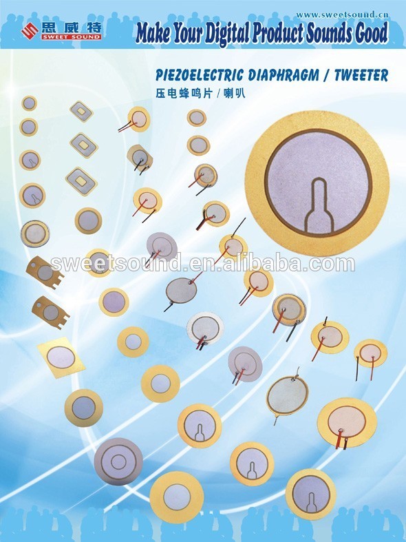
diaphragm
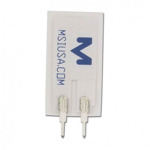
strip
As a next step it makes me want to try adding a resistive load.
I also read about other piezo device, that might also be repurposed into energy harvesters. This video demonstrates a piezoelectric motor:
The piezo motors can be rotative or "solenoidal", compagnies such as PI- Piezomotor sell them. They are often used in photography.
Would those devices recover energy more efficiently? Maybe but this would raise the porject cost drastically. This would be a nice track to improve a final prototype.
Last reflexion I had on piezo is, is the voltage function of the PZT volumes of its deformation? I saw that piezo ceramics powder -sold vs. hard- was sold. One other track would be to mold custom-made piezo. Villette Makerz has some ceramics oven.
Peltier effect
I wanted my harvester to be multi-source. So if it was able to work with temperature difference this would be interesting. I wanted to test my Peltier module but it can't simply be plugged in or risks to be damaged. A heat sink should be added to the hot side and linked to it with a thermal glue. I will purchase such a glue and make a test. For the heat sink I saw small ones at Letmeknow. Those are be quite cheap. From what I read the temperature needs to be quite high at an interface and often requires fluid circulation. My small Peltier module is a TEC-thermoelectric cooler- and TEG-thermoelectric generator- are strongly advised to produce thermoelectricity. The only issue is the price of TEG technologies.
Energy storage
To store more energy, the use of supercapacitor is recommanded. This is why I ordered 2 with different capacitances (1Farrad and 330 mF)
Design
I was thinking about a design. I would like something good looking. I considered fixing the piezo on a soft surface. I considered wood. I saw a nice pattern with double curvature. I made a test with the hexagonal pattern.

pattern
setting
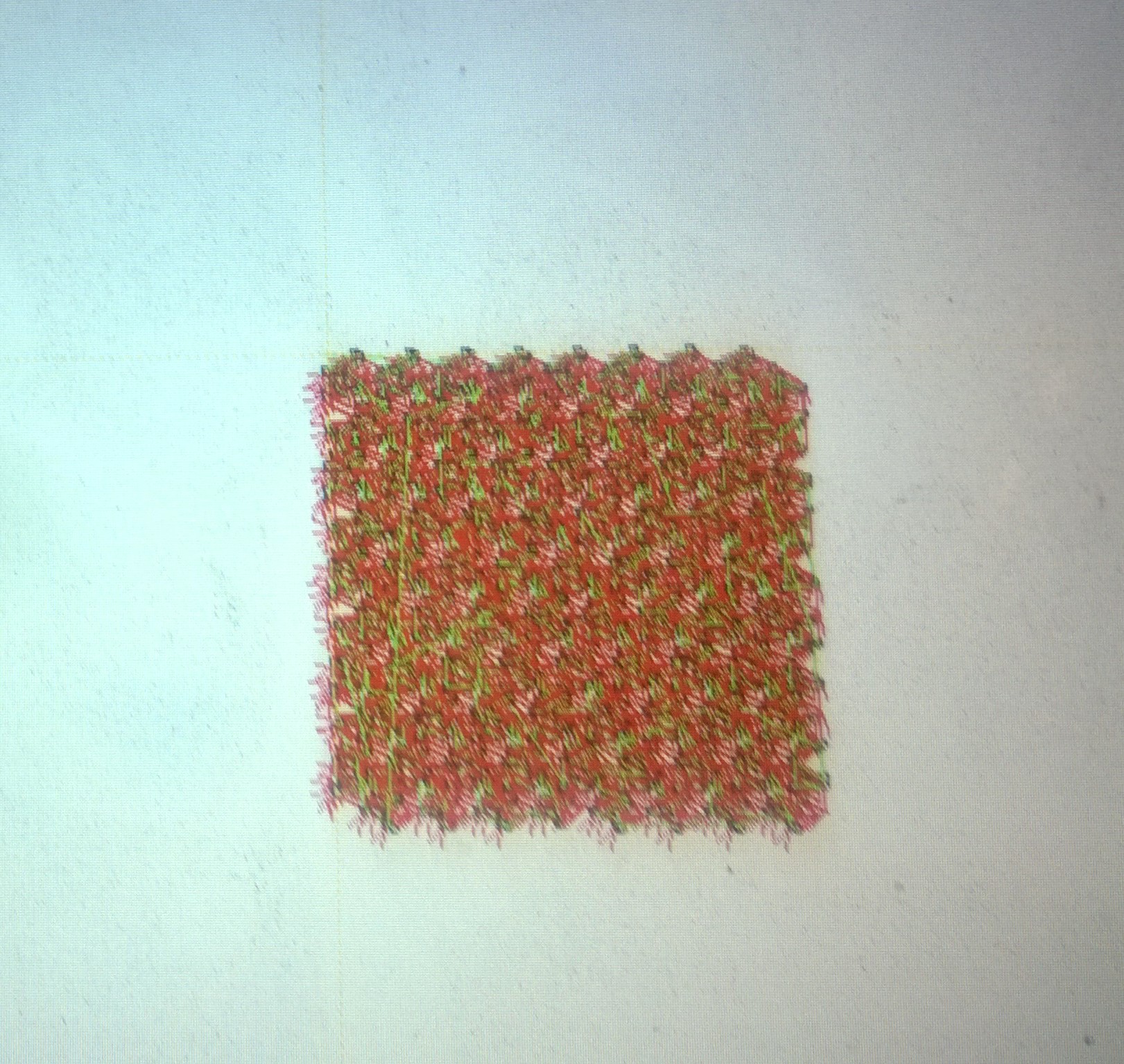
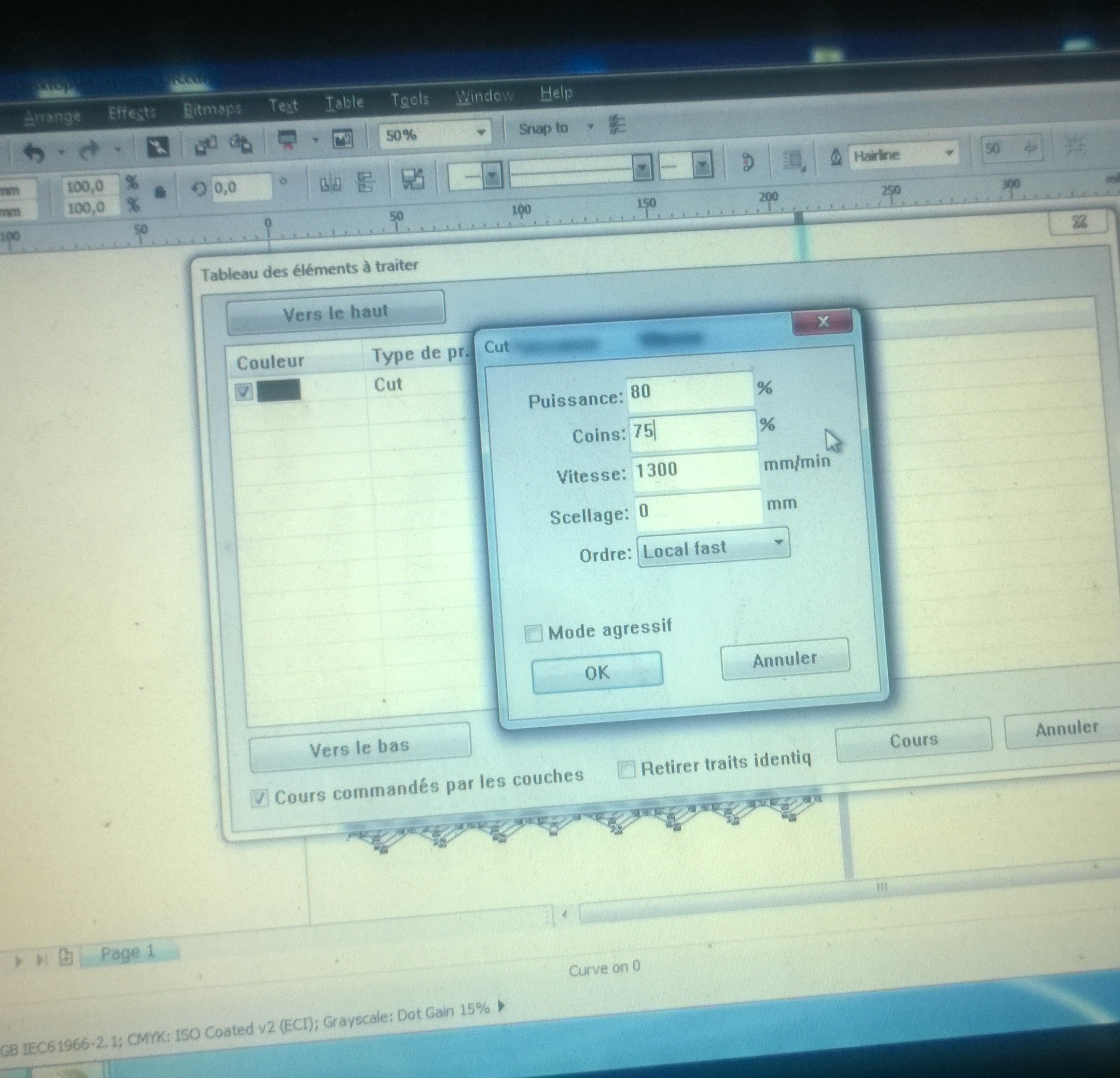
path
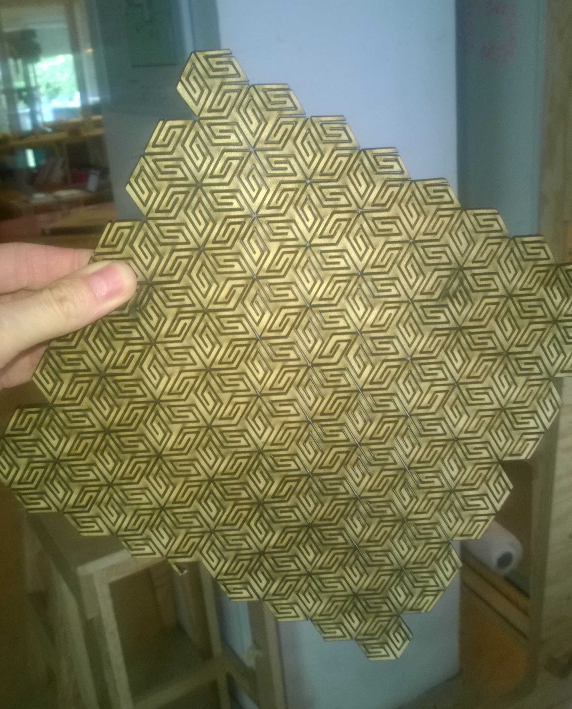
test cut
In Corel Draw I switched all the lines to black and combined them. The lasering was quite long as the path density could have indicated. The laser was maybe too strong as the bottom was completely carbonized. The coupon could bend in all direction but was quite fragile.
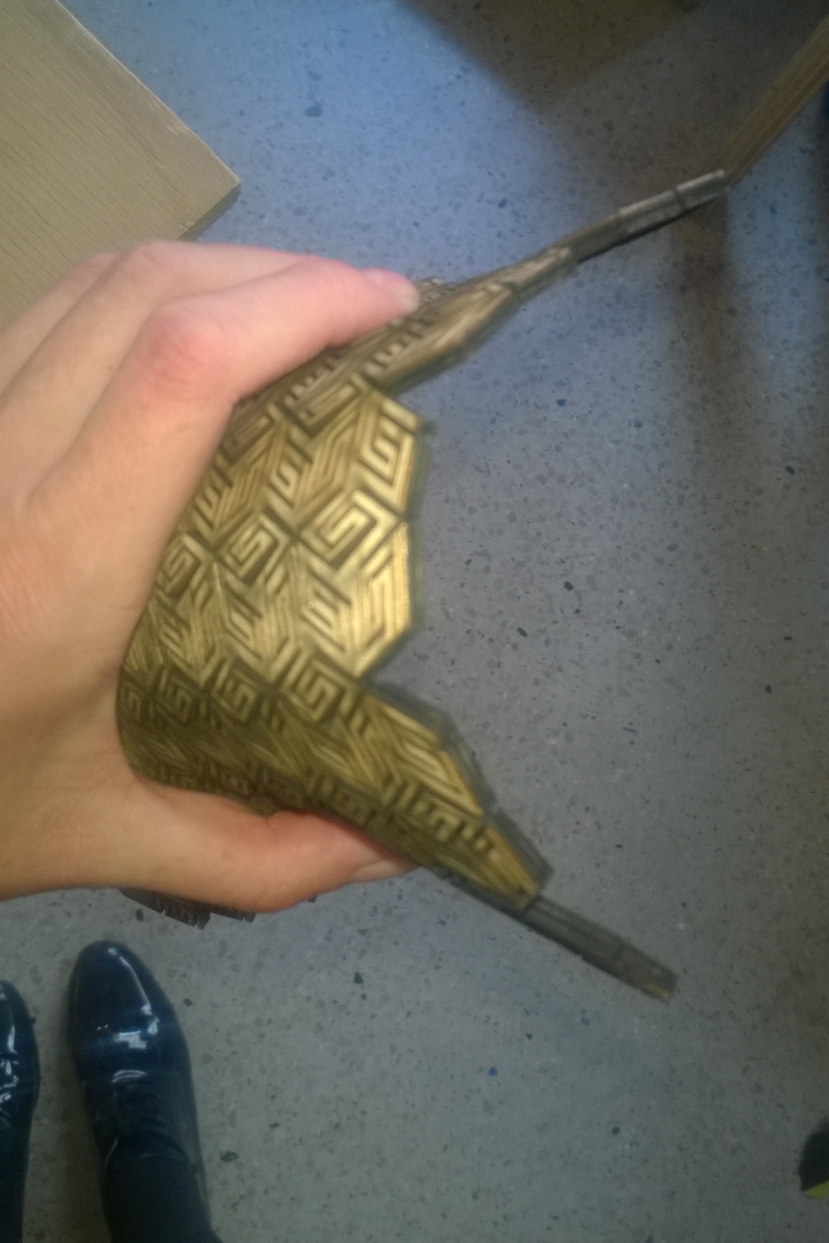
bending
Maybe building a composite could be quite nice. Adding an impermeable fabric between the wood and the electronics could be a good call or a thin layer of silicon.
Let's say we have 3 weeks. I consider the week to have 6 working days.
The first week will be dedicated to tests and validation
| D1 | D2 | D3 | D4 | D5 | D6 | |
|---|---|---|---|---|---|---|
| Testing kerfing wood with the laser | Testing energy harvesting system: Peltier vs. piezo | Testing energy harvesting system: Solenoid | Building solenoid | Testing energy storage and saving (watch dogs..) | Testing different designs with 3D printer/laser cuttings |
The second week will design and model in 3D.
| D1 | D2 | D3 | D4 | D5 | D6 |
|---|---|---|---|---|---|
| Energy harvesting sytem design | Energy harvesting sytem design 2 | Board design: slave | Board design: master | Tiles deformable part | Tiles static part |
The third week will dedicated to the production and the tests.
| D1 | D2 | D3 | D4 | D5 | D6 |
|---|---|---|---|---|---|
| Energy harvesting system production | Documentation | Board design: slave production | Board design: master production | Tiles deformable part molding | Tiles static part milling |
Success criteria
I will have several KPI:
-the overall energy consumption with plug-in power meter as soon as a tool is used
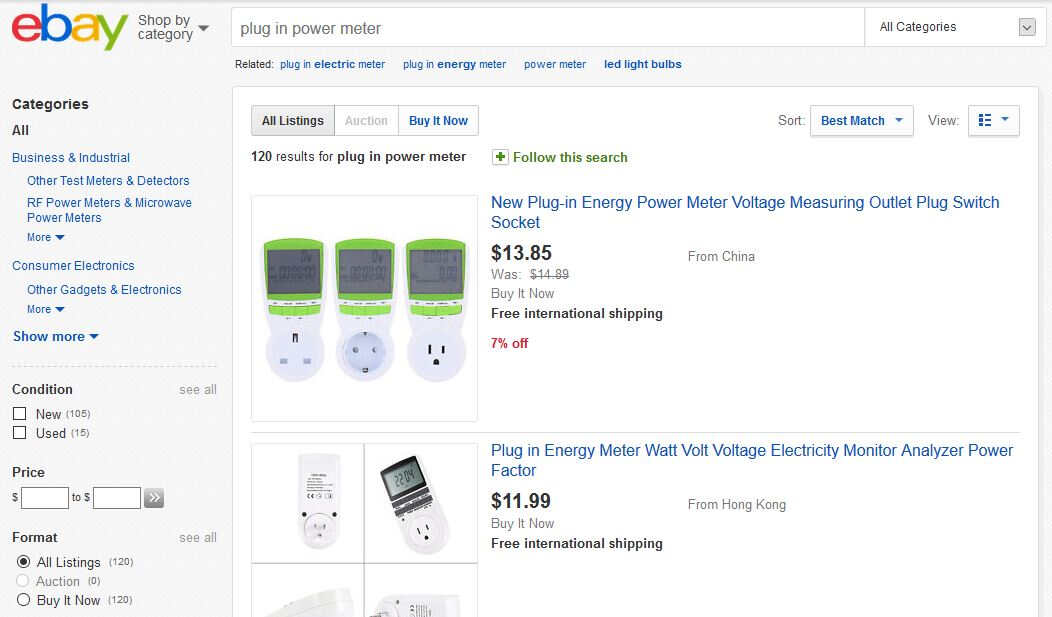
plug-in power meter
- The energy autonomy of my device, even if the goal isn't 100%, I would like to have a consumption decreasing as the project progress.
For this project I am planning to use:
- 3D conception with Fusion
- CNC for the structure boards
- Molding for the covering
- 3D printing for the mechanical parts
- Electronical conception with Eagle
- Electronics for the boards
- Programming for the electronics and the interface
This was a rich review as most attended. Bianca presented her final project: a moisture sensor for plants. Joris told us about his modular lego sensor (a VOC-the most expensive-, a led, a Wifi, a humidity sensor one). I was the next one. A drawing is lacking on my page but Aldo gave me really nice references from IAAC self sufficiency research . IAAC investigated self sufficient biosystems organized in tiles. In one project the tiles mimick valleys so the water is running through it. In another one material with each having its specificity/functionality are stacked. Aldo think going in the organic direction might be a good idea as well as embedding organisms. He also told us about his project of large printing in clay, about how cracks formed as the material retracted and how they are about to print mycelium along clay to prevent and heal the cracks. The mycelium mimicking tree roots. He invited me to consider the context of the tiles, its environment. Yassine described his underwater sensor, he drew very synthetic illustrations. Denis told us abut his granular grip, he gave us a nice reference: the soft robotics toolkit. He is first planning to build a 2D silo. Aldo mentionned the self-assembly lab and the aerial assembly project. We were reminded that the final project should have the following components: an electronic part, a mecanical one, a 3D production and an interface.