Exercise 06 - Electronics design
Redraw the hello-world board, add a button and a LED, check the design rules and make it
Istalling Kicad and Eagle
First I installed Kicad because my 10.8.5 Mac OS was not supported by the last version of Eagle.
Very soon, during a quick explenation by my collegue Emanuele which is informatic engineer, something wierd happened with the libraries in the window for the editing of the traces.

We tried to fix it but we didn't get to the solution.
At this point Enrico Bassi ironically suggested me to change lap top and get a new one, but I didn't give up: I just put a new SSD hard disk and 2 GB of RAM more so my lap top year 2008 was flying.
I looked for an older version of Eagle where my OS was still supported. So I found a page full of old versions of Eagle.

Starting point
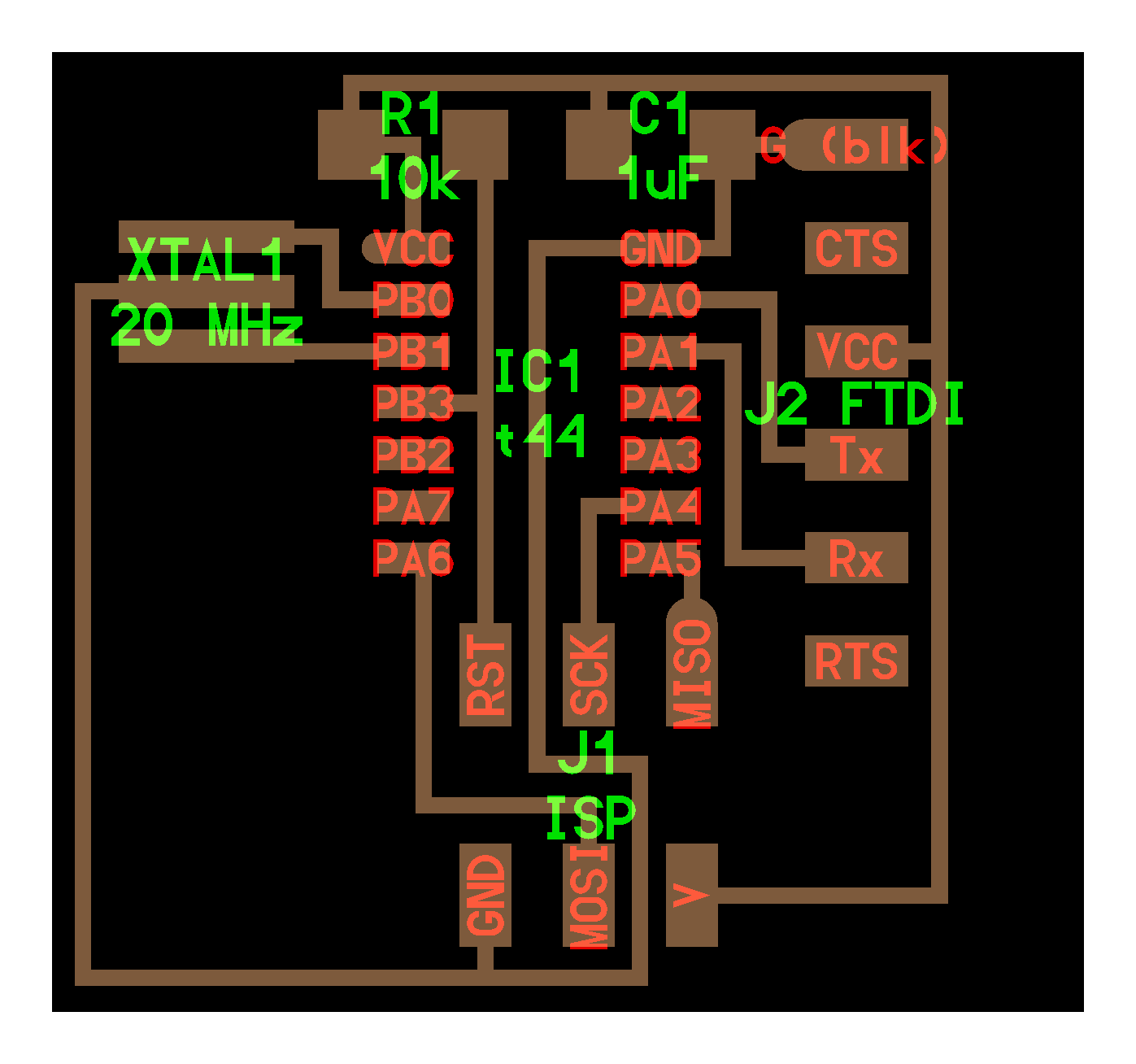
This was the base Hello-World Board without any output.
Designing with Eagle
I read some tutorials about Eagle and electronic design that I recommend:
- this one in the Fab Academy archive;
- this and this by SparkFun about how to do schematics and board layout in Eagle for beginners;
- this video about how to do better PCB layouts by SparkFun.
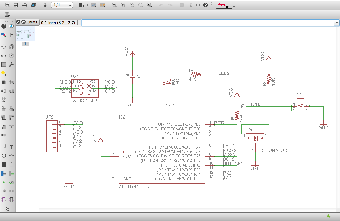
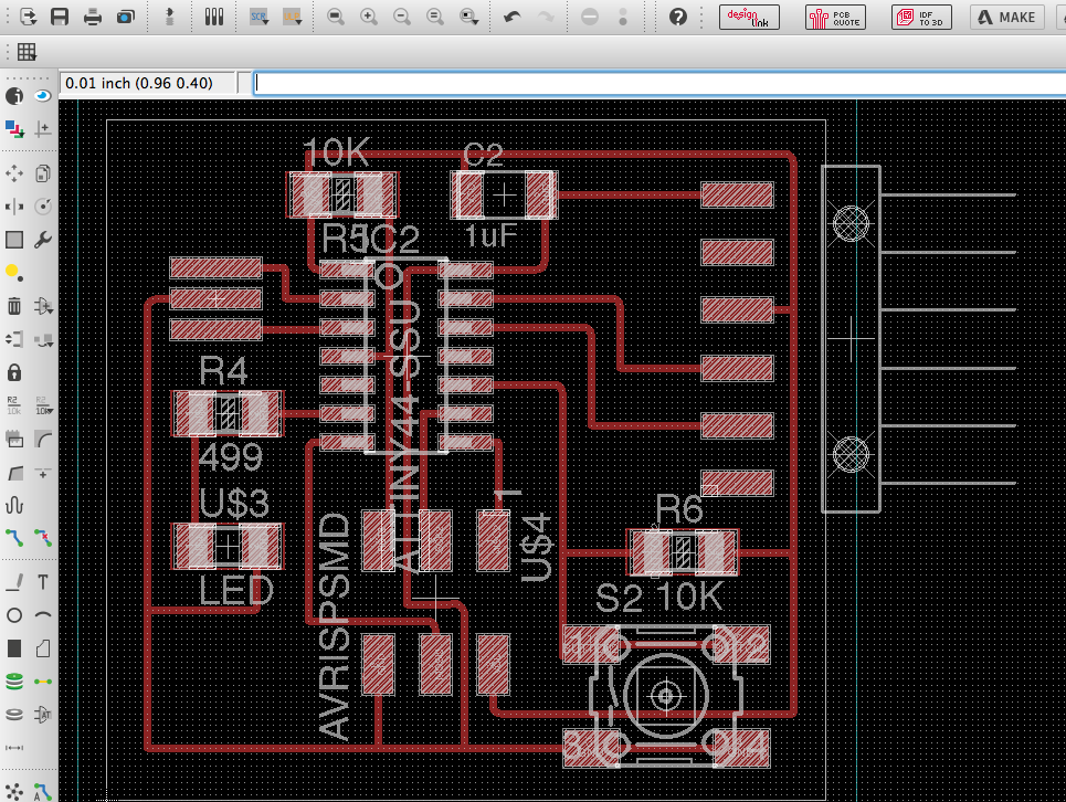
After studing all the tutorials above (it took to me two afternoons) I started using Eagle and drawing the schematics.
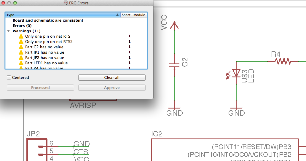
I checked for errors using the tool ERC = electronic rules check. It was usefull to correct some mistakes mainly about lines and values not matching.
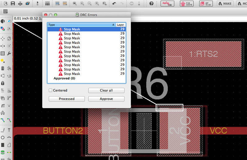
I checked for errors also in the board view with the tool DRC - design rules check. This time I didn't find any error.
At the end the board looked this way:
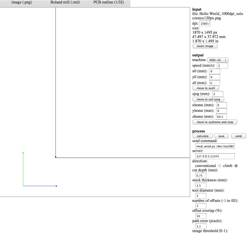
Fab Modules
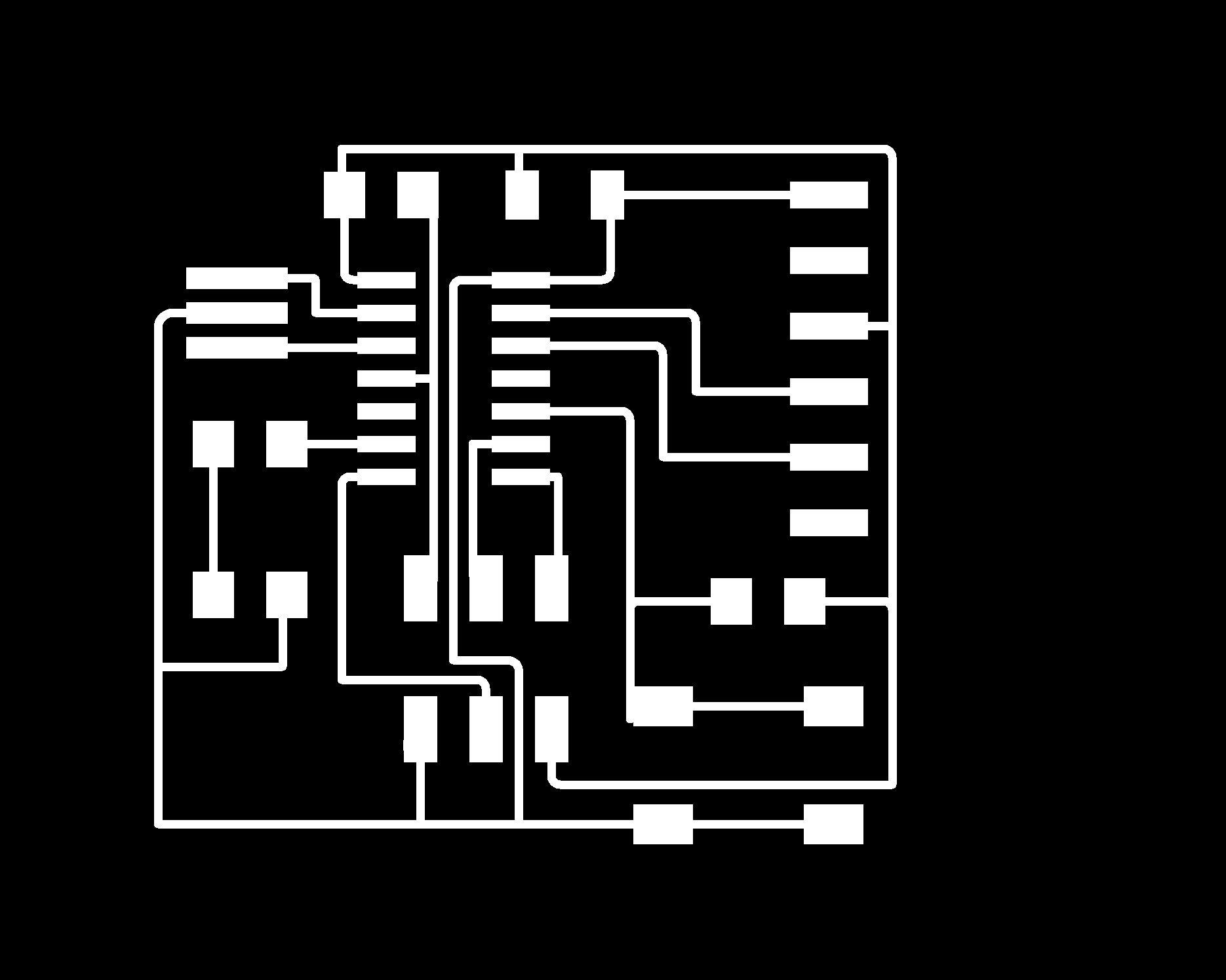
Following the tutorials I exported the .png file with only the traces and I opened it with the Fab Modules. At this point I followed my documentation on my Exercise n.04.

Milling and soldering
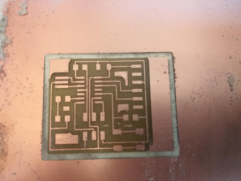
First board was not properly milled, there was a problem setting the zero z coordinate.
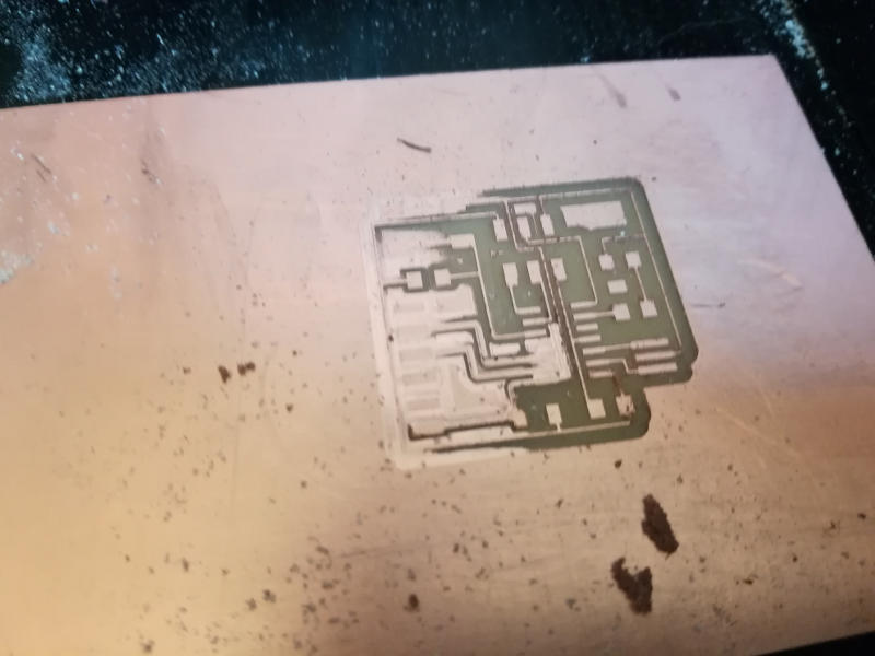
Second time was better:
Finally I soldered all the components:
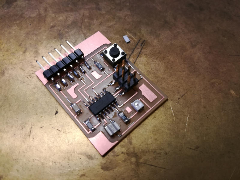
I programmed this board in the Exercise n.08.
More electronic design
You can check more examples I did of electronics design here: