Assignment:
A_ Design a board that integrates sensors to control devices
B_ Program the board to capture datas
B_ Program the board to capture datas
A_Design the board.
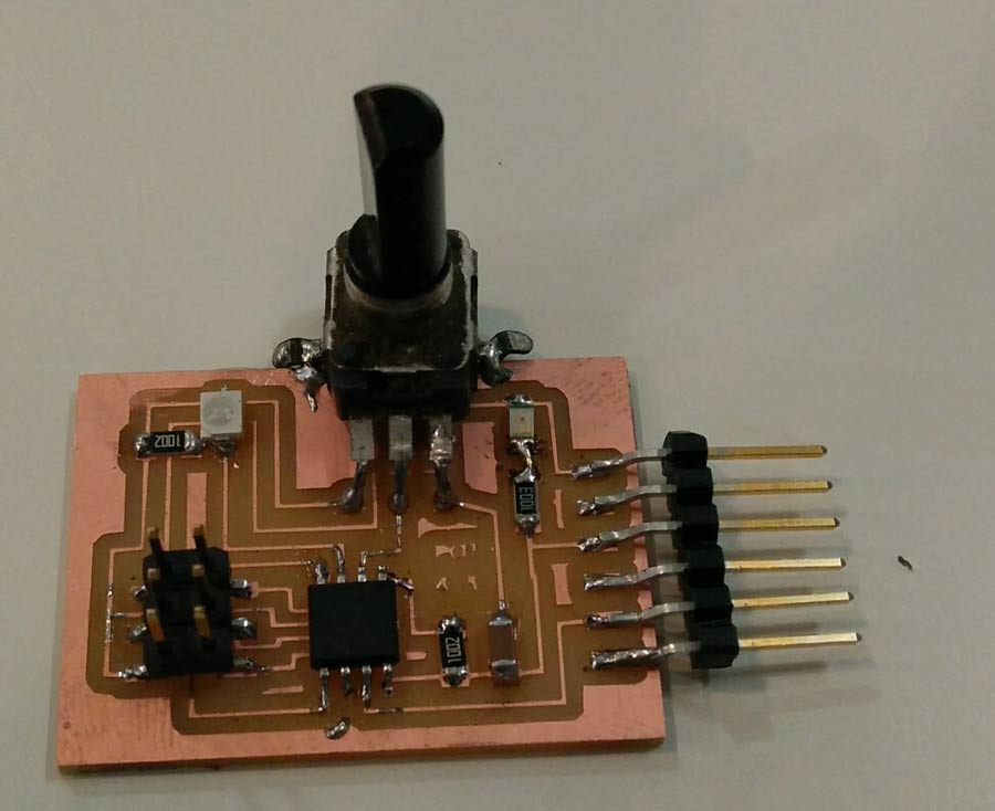
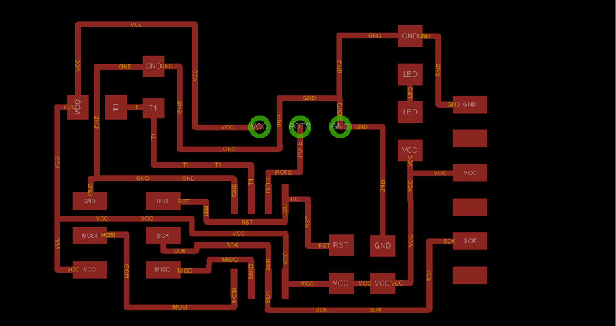
I will use the Hello.light.45 board as a template to which I will add a potentiometer connected to the free pin of the attiny45. I will also add a led connected directly to current so it turns on when the board is connected
e
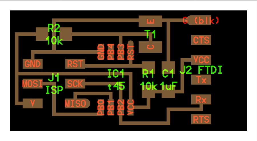
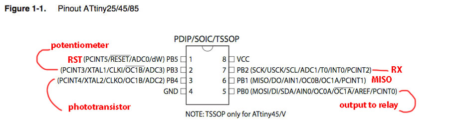
I connected the phototransistor to PB4 and the potentiometer to PB3 so it can be placed between the sensor and the led - avoiding the led light to spill on the light sensor and influence its reading.

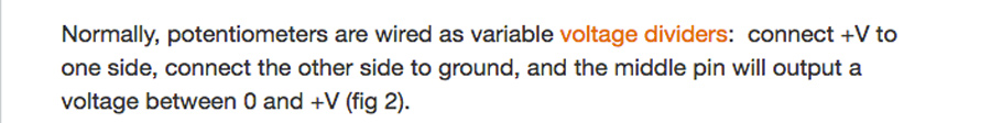
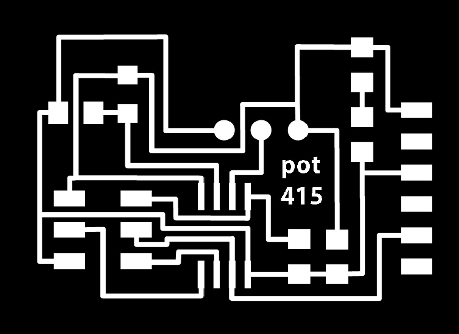
The potentiometer I found in my lab's inventory did not exist in any library that I found for Eagle so I chose a component that apparently had the same pin size. The actual component is much bigger than the board and I like it like that. I connected the pins following these instructions:
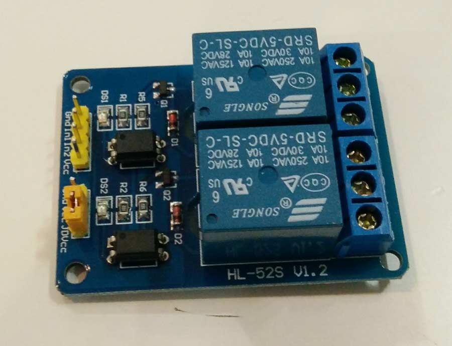
I would like eventually to use the MOSI pin of the Attiny to trigger a relay connected to 220volts once the Attiny has been programmed.
Bill of component:
(1)attiny45
(1)6pin header
(1)ftdi header
(1)phototransistor (light sensor)
(1)Resistor 10K(R1)
(1)Resistor 10K (R2)
(1)Capacitator 1Uf
(1)potentiometer (3 pins)
(1)Led
(1)resistor 499ohms
NOte: After programming I could not get any lecture from pin4 and realized this board has mistake. (See the corrected board further down this page).
B_ Program the board to capture datas.
I first downloaded the files to program the board make, C and python from the fab Academy page and saved it on my desktop. In terminal I installed the .make file, selected the usb port and executed the python code.
The terminal commands I used to program the board and run the program are the following:
Go to the directory where the files are saved
load the C code on the Attiny through either the FabIsp or the Avrdude programmer.
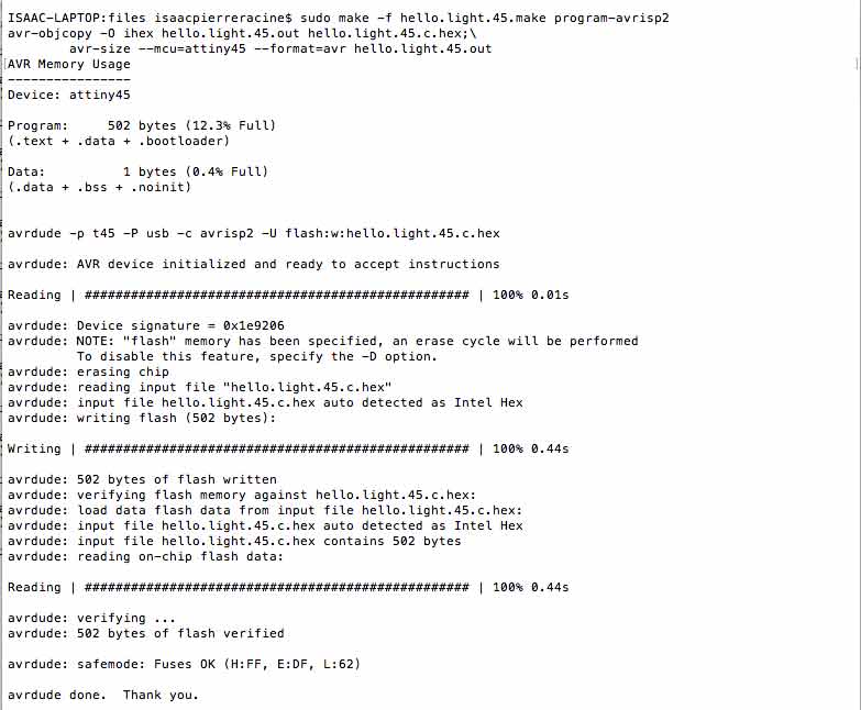
sudo make -f hello.light.45.make program-avrisp2
This creates a .hex file and an .out file _ making the Attiny ready to receive instructions/program, and allowing the AVRdude (or FabIsp) to program the Attiny. The message at the end should end up with: THANK YOU.
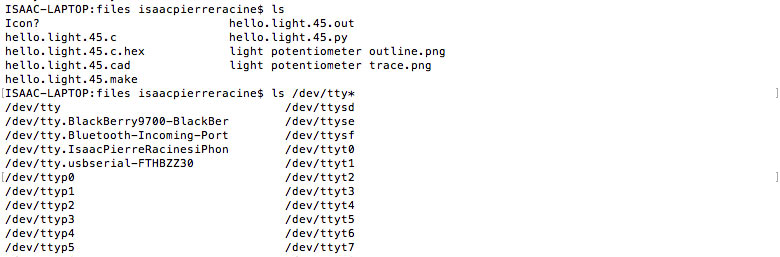
Now to execute the python code fron Terminal we need to identify the serial communication port the computer use to connect with the board.
To do that type:
ls /dev/tty*
A list of available port will come out. The one with a name that includes USB (because the FTDI cable from the board is connected to one of the computer USB port.) is the one to select. In my case it was: /dev/tty.usbserial-FTHBZZ30
type:
python hello.light.45.py /dev/tty.usbserial-FTHBZZ30
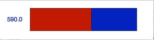
The Python interface will open and show the graphic window and the values from the potentiometer
I ran the C code from termnial and the python executed properly. As expected it is the potentiometer instead of the light sensor that controled the graphic interface since I have swapped the pins in the design. In Neil's board the ligth sensor is connected to pin PB3 but in mine it is the potentiometer connected to that pin while the light sensor connects to PB4. I did that to solve a routing design issue in order to hide the led from the light sensor placing the potentiometer in between. This video shows how the code was executed and the interface at work.
While the assignment is formally completed I would need to adapt the code so the light sensor and the potentiometer can operate together and in a complementary way. That implies to create an equation of variables so the potentiometer can be used to adjust the sensibility of the sensor, turn the relay on and off without having to reprogram the board. To get the relay to operate from the Attiny I also need to reprogram the mosi pin as an output that can trigger the relay.
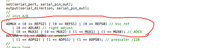
I had in mind to reprogram the board by editing the C code provided by Neils so the light sensor actuate but soon realized it was a very complex task for my programming skill level. Even though I did not succeed in the intent I studied the datasheet and understood I would have to reconfigure the bits of the ADC3 pin -which cooresponds to PB3. To reprogram a pin in C. I would need to change the register. I tried to understand what that actualy means, how this could be done but I could not get anywhere except from identifying the lines of code I would need to edit.
Seeing that I would not get anywhere doing it from the C code I turned to Arduino but time was running out and I could only get to identify the pin corespondance between the attiny Arduino pins.
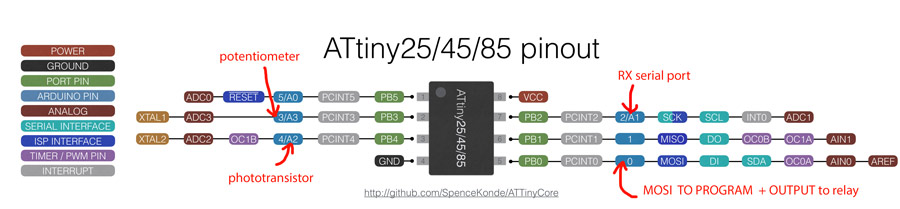
PB2= PIN2 (digital PWM) or A1 (analog)
PB3= PIN4 (digital PWM) or A2 (analog)
PB4= PIN3 (digital PWM) or A3 (analog)
Also the PB0 pin of the Attiny that is used as MOSI while programming the board can be used as PIN0 for the output to trigger the relay.
I need now to write the sketch using analog read command for the sensor and the potentiometer in serial communication mode and program the output to trigger the relay.
I managed to read the potentiometer values through the Attiny45 PB3 pin (Arduino A3) but I could never get a proper reading from PB4(Arduino A2). I have struggled a lot with it and realized there was a mistake on my board. The photosensor was not connected to Ground.
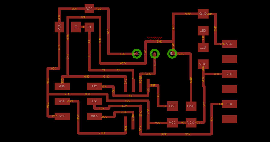
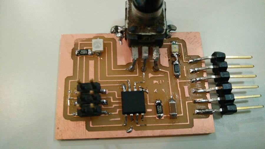
I corrected the diagram and the board on Eagle and milled a new board. But this time instead of a potentiometer I soldered a 3 pin female so I can connect the potentiometer or other components.
The new board worked just as the previous one but I stil could not get around to make it read the phototransitor. I studied the datasheet of the photoresistor, made a series of tests by-passing the phototransistor, changing the resistor but all I could get was an erratic reading and very minimum change in the value reading. (for example 1023 to 1014) while the potentiometer was showing a complete range (0 to 1023)
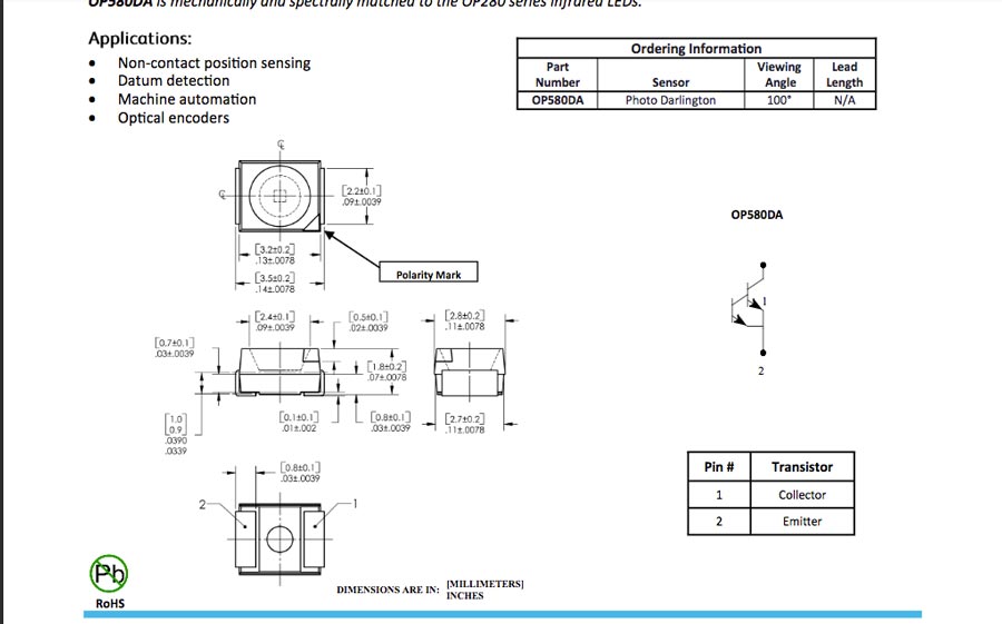
ground emittor- vcc receptor