Read a microcontroller data sheet.
Program your board to do something, with as many different programming languages and programming environments as possible.
Optionally, experiment with other architectures
Learning outcomes:
1)Identify relevant information in a microcontroller data sheet.
Datasheet
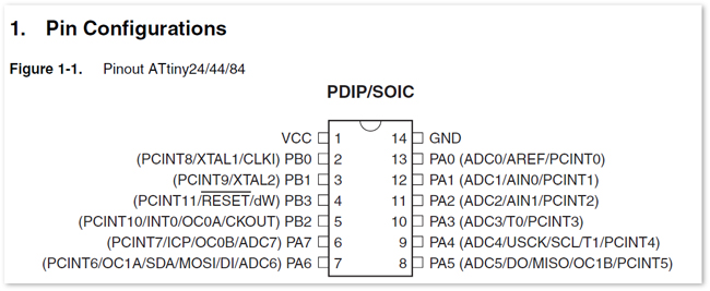
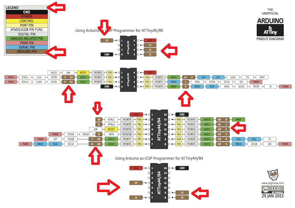
I read a datasheet on attiny44, i think that the most important is learn about the pin configuration, I let you a image to learn this.
2)Implement programming protocols.
I have to burn bootloaders, it is a serial communication using a USB port to I2C on the Attiny, and the charlieplexing technic to activate a lot of led with less pins.
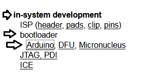
You can find information Arduino Bootloader
Here
This picture is of the electronic design week in the schedule of Fab Academy
You can find all the necessary about arduino bootloaders
Have you:
3)Documented what you learned from reading a microcontroller datasheet.
I learned the pin configurations, the characteristics of this pins, the voltage source level work it,it has a EEPROM memory, it can be reprogrammed. Worksource level of pins.
4) What questions do you have? What would you like to learn more about?
Why you can not use the same configuration of the attiny pin?
I want to learn about programing language.
5)Programmed your board
6)Described the programming process/es you used
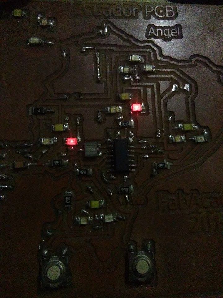
I used the PCB than I created in my assignment of Electronic design. the Ecuador PCB
I decided to make my program on Arduino.Ide software but I was using the DDR and this software do not let me work with this,
the DDR function makes a port configure like inputs or outputs, when you put 1 it is a output and 0 is a input.
Example: DDRA=B00001111
you can see DDR (A) is the port than you want to configure.
(B)(0000)(1111) B is to declare as a binary, and the 0000 is an output and the next 1111 is a input. but when I use it on Arduino.Ide it sends me an error when I compile the program. see the picture.
I was looking for information and I could see my fail, the error is because I got confused, I was using the language to program in Bascom and it is a little different to Arduino.
but you can find all the information to program in the official page on arduino.cc.
I was so tired to try to program and simulate the program on Proteus. i did not understand why the configuration change the ports on my simulation,
I select the port A0 to turn on a led and when I simulated, the pin was not the correct than I configurated on my programing.
It is because when you use the library to attiny you have to looking for this image. It is the attiny pinout, you have to see the chart on the left, the Arduino Pin, when you are programing take in count, the pins change the name in the image, you have to use this configuration.
3) Described the programming process/es you used
All the previous information is new, I was trying to program without this information. I was so tired and I decided to program using Bascom AVR, Bascom AVR is a software to program AVR, I had a little of information of this software and decided to do mi programing on this software.
I used the DDR to configure inputs and outputs. and PORT to turn on or turn off the pins.
All than do you have to know is,
$regfile = "attiny44.dat" ,it is the command to select the attiny44
then you have to choose the crystal with the next command $crystal = 2000000 , it is the selection on my crystal of and the value of this.
DO and LOOP is the place where we make the repetitive programing. you have to write DO to start your programing and close it with LOOP
you can see all this configuration on the file than you can download in the final of this page.
If you finish your programing, you have to save, check and compile, see the image to see the steps, if your programing is not good, the software sends you an advertence on your window, if it is right you can compile the programing.
when your program is ready, it creates a file .hex in the folder than you save it.
I use the file .hex to simulate mi programing on Proteus, you have to create the schematic in proteus,
add the electronic components and connect these, when all the components is ok, you have to upload the file .hex than you created on BascomAVR,
Double click on the attiny, it opens a window, in the option "Program file" you have to looking for your file in the folder than you save it,
select the Crystal, 20MHz in my case.
press ok and play to simulate.
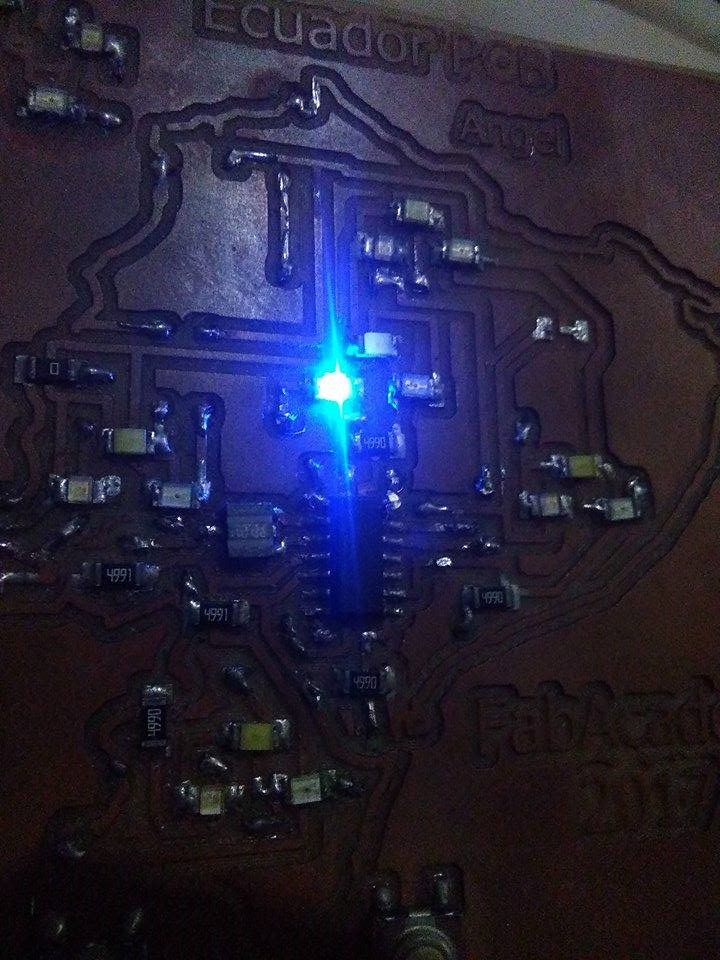
In this design is really hard turn on led lights, it is because you have a lot of leds in different positions.
Here in the picture you can see the leds turn on.
7)Included your code
code and Schematic proteus
In this design is really hard turn on led lights, it is because you have a lot of leds in different positions.
Here in the picture you can see the leds turn on.
code and Schematic proteus