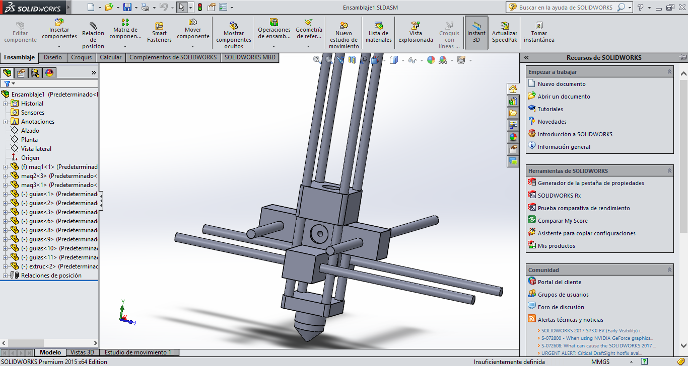
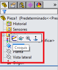
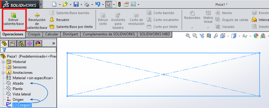
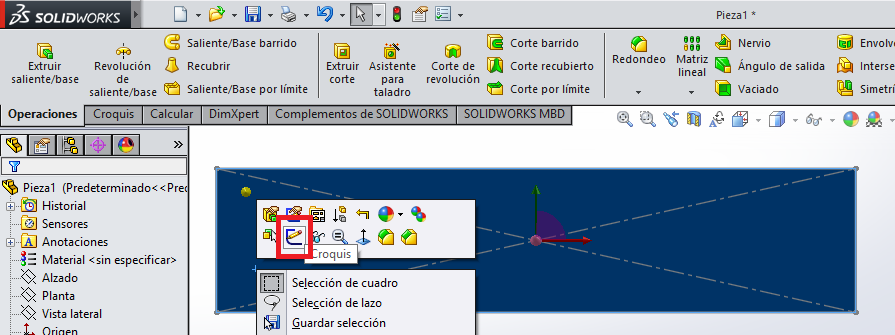
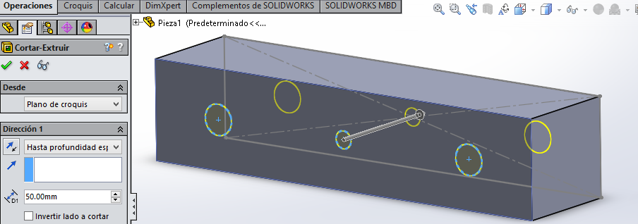
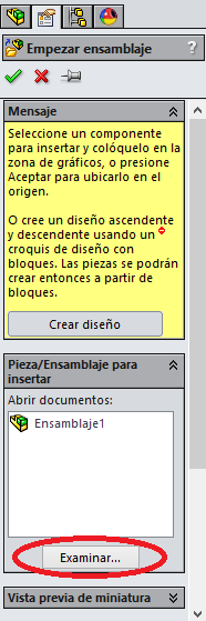
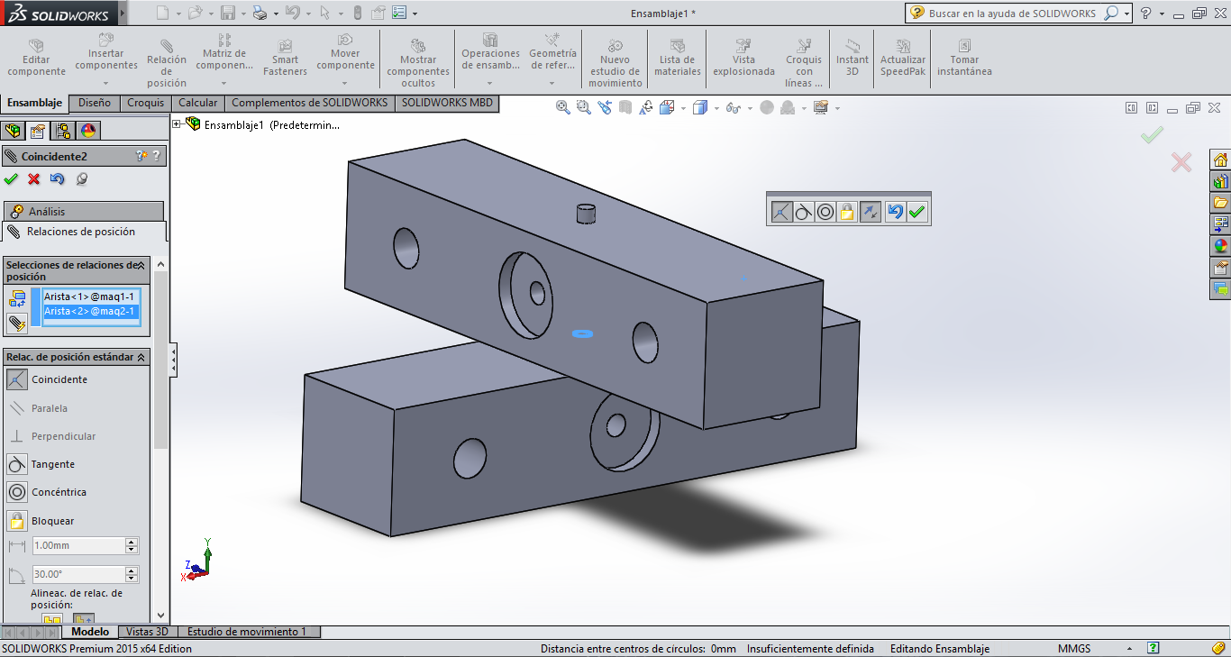
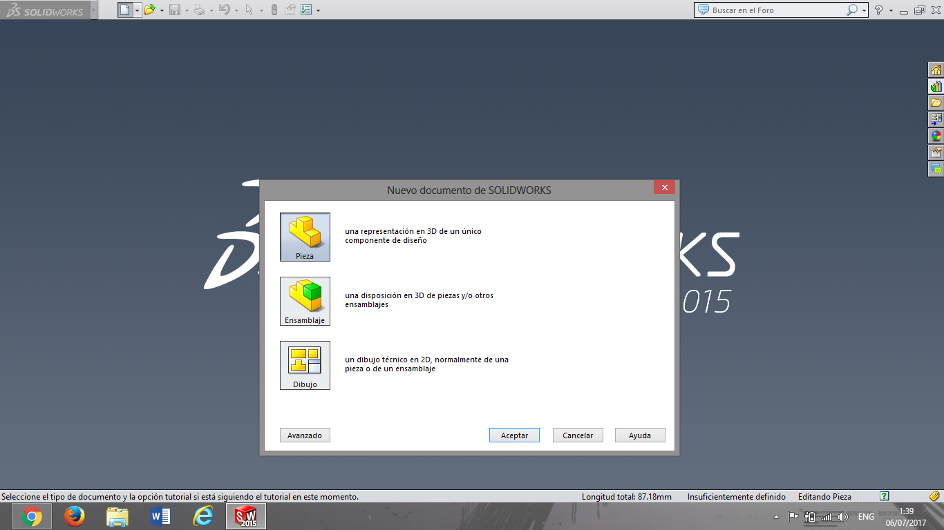
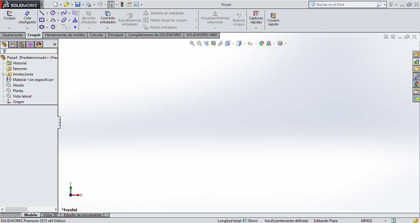
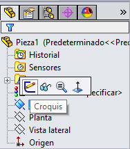
Before you start drawing we must know some essential commands to draw in Solidworks. Select the correct area of you need work, in 2D you select sketch in the area you decided to
work, this sketch you must click in the area and select the icon with a pencil.
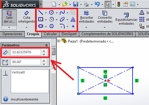
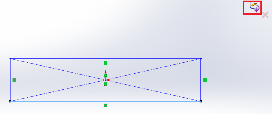
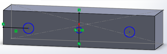
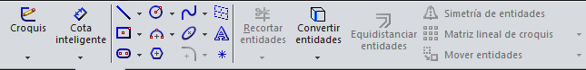
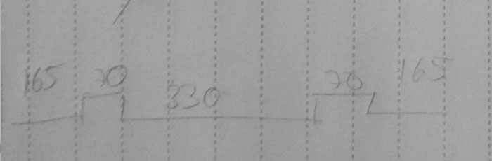
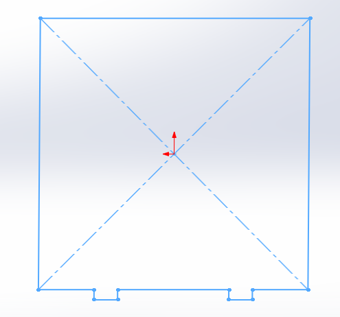
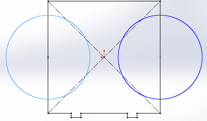
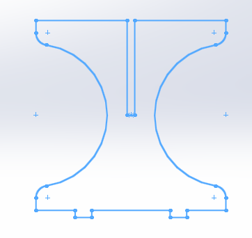
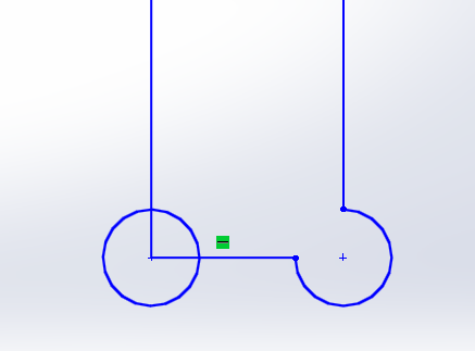
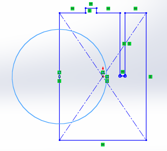
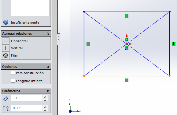
based in sketches, drawing with the commands seen using the tool center rectangle to make a square fast with the measures annotated, make a circles of radius 300 mm in the middle
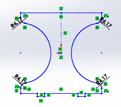
of the line, using the tools sketch rounding and trim entities, remove the excess line and sketch rounding rounded the corners, finally make a coupling to fit the pieces of 32 mm.
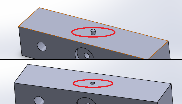
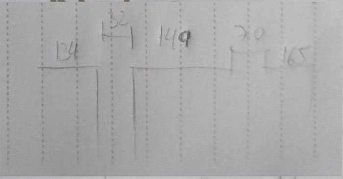
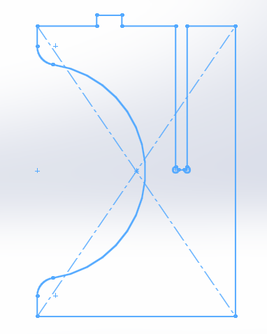
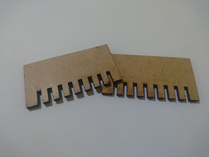
In the second design also based in sketches, first make measures of the top line of the sketches with the tool center rectangle make a square and the couplings in the space of 31
this measure is different of sketches because corrected at dimension of material, dog bone in the couplings for So that the feet can be adjusted completely, and we repeat the previous
process make a circle of 300 mm of radius and complement with tools sketch rounding and trim entities to finish the design.
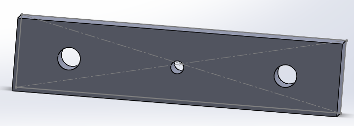
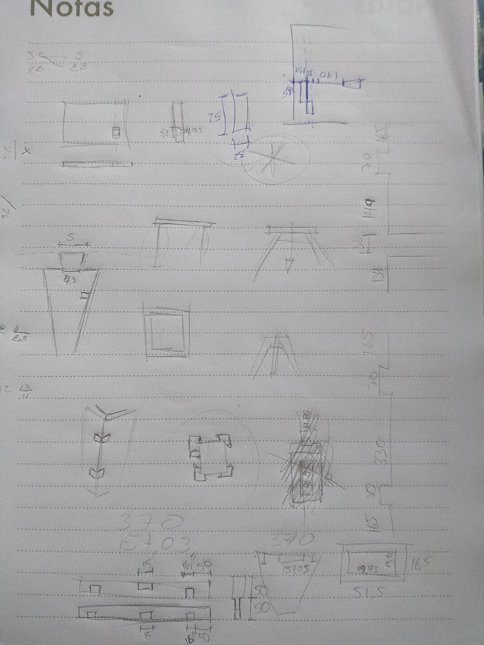
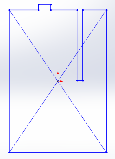
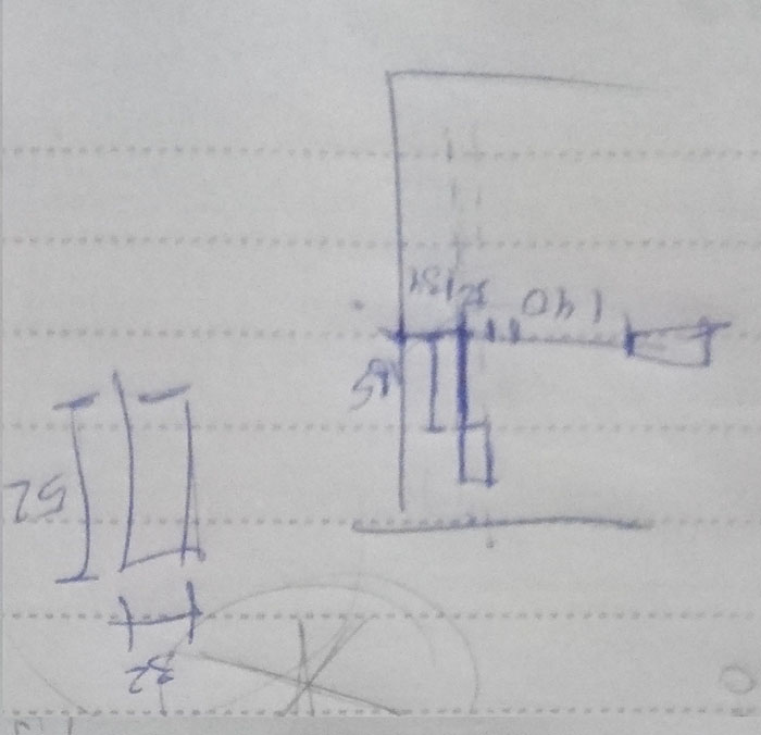
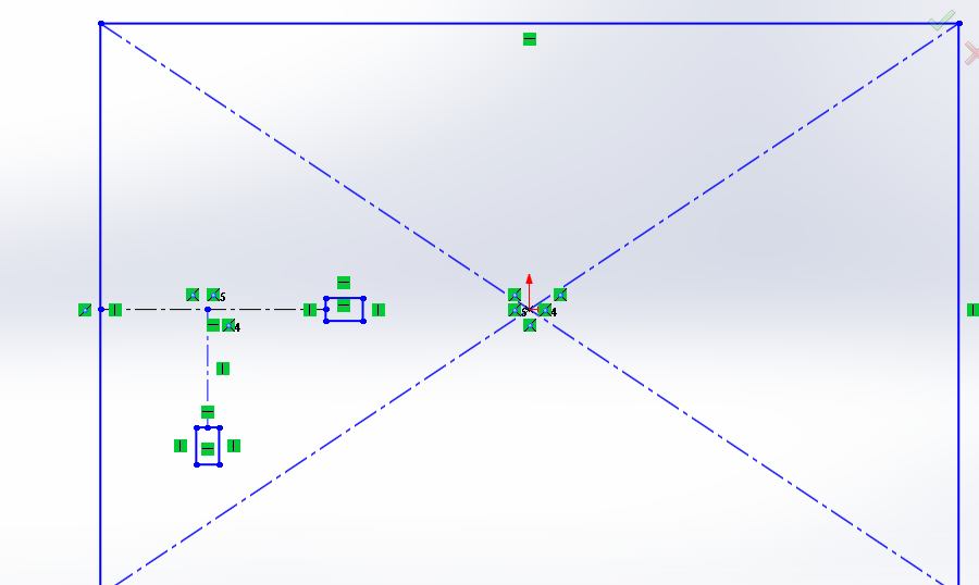
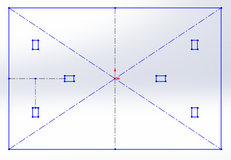
In the last piece make a rectangle for the table, to situate rectangle since the middle of the lateral line measure of 134 in horizontal and 165 in vertical to point to make
rectangle, to second rectangle, take de same measure in horizontal 134 and add 171 for make the rectangle starting from the middle and use the tool symmetry of entities to complete
in all de design.
2D software
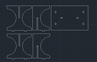
Autocad
Autocad
In this assignment, I test this software for make the same figure that I did in the previous software, then make the design in Autocad, you must take into
account the measures in which you are making the drawings also with the previous software, when finalizing grouping the lines to handle more easily in the software Inkscapethis,
software is very simple of use but not is parametric design.
- Demonstrate and describe processes used in modelling with 2D and 3D software
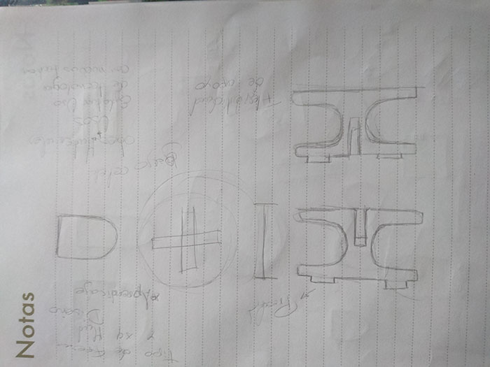
For this process, I did screenshots and a tracing of the design and who made this process and explain some tools all this documentation you can see in the first objective of this page.
have I:
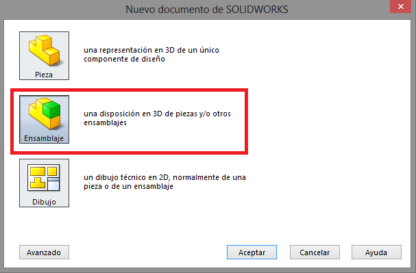
- Modelled experimental objects/part of a possible project in 2D and 3D software
For the model in 2D and 3D use SolidWorks because this software work in the two models, the example is described in the top of the page.
- Shown how you did it with words/images/screenshots
All the images and screenshots you find in the two objective in the top of the page.
- Included your original design files
Dwonload files
FIles in Repo.