#week 15
Embedded Networking and Communications
This weeks assignment
Design and build a wired &/or wireless network connecting at least two processors
This weeks assignment has been one massive debugging project - and the moment where the LED was actually blinking when it was supposed to - was AMAZING.
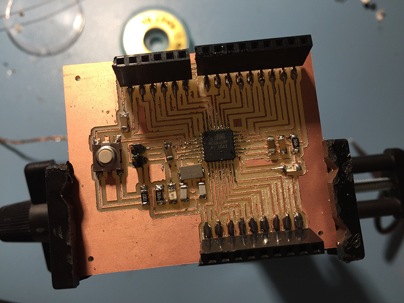
I started of using 2 different SatschaKit boards. You can find the process of fabricating the board and programming it under my Final project page.
This time around I did not have a 16mhz crystal, so I tried to programme it with a 20mhz crystal 10pf capacitors.
That was the first error.
It turned out that you have to use the 16mhz crystal and the 22pf caps. The reason for this is that you will not be able to program the board.
So I had to order more of the 16mhz crystal, with the 22pfs capacitors. This took a few days, but I got them and soldered them on.
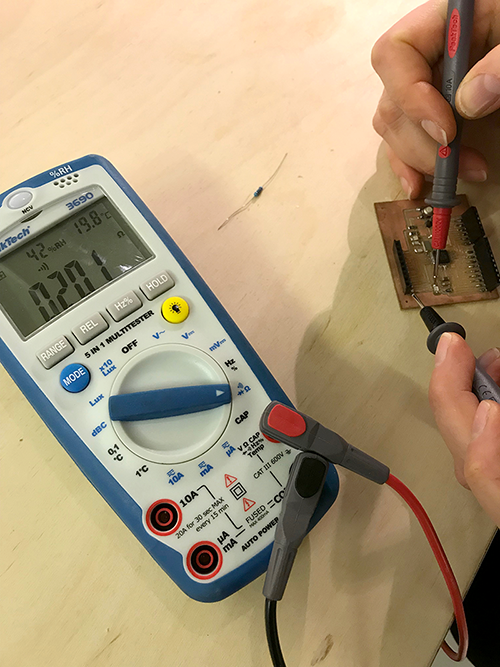
Since the soldering was a bit scruffy, I cleaned it up as best a I could and did a roundcheck with the multimeter to be sure that that all the connections was working, and everything seemed to be working fine.
This was the second error.
Being stressed and in a hurry, I did not notice that I had ordered a 16mhz crystal - with the wrong footprints.
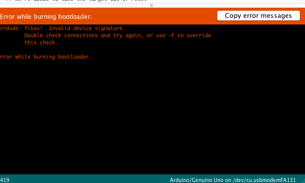
This caused me spending a couple more days trying to figure out why I kept getting this error.
"Yikes! Invalid device signature"
In the end, it dawned on me that it might be something with the crystal, so I took it off - and could see that the footprints was totally wrong. Even though the footprints was wrong, it was still the size and placement (the crystal had 4 small corner footprints but the PCB had two big ones)
So I made a new round of the right 16mhz crystal.
When I recieved the new components - I soldered it on, and I finally got to burn it with the bootloader - on the first try!
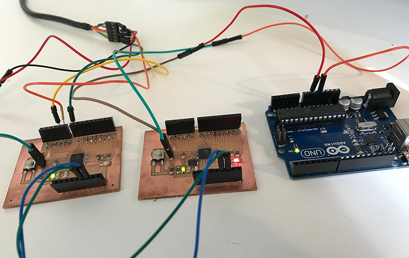
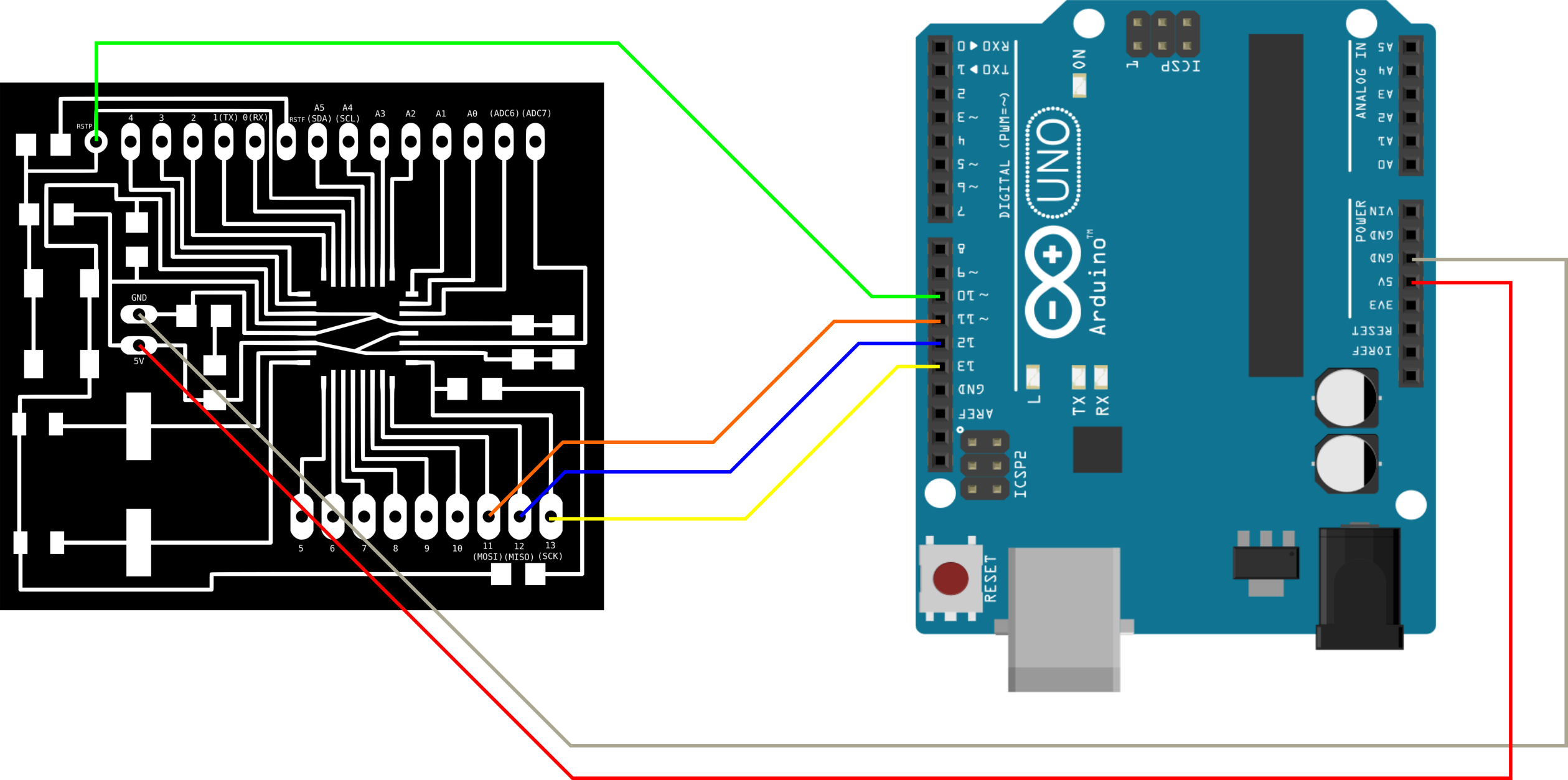
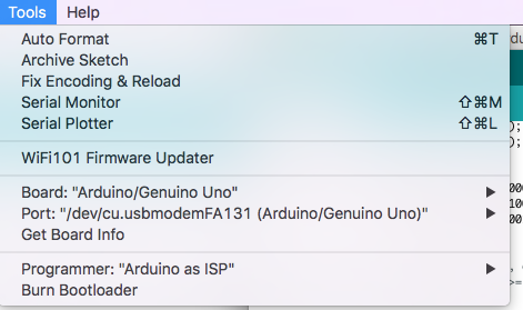
For burning the board with the bootloader, I used another Arduino UNO board, where I connected it as on the illustrations, and I used these settings.
Remember to also add the 10pf cap between reset and ground after you have uploaded the ArduinoISP code the Arduino UNO, and before you Burn the bootloader. (as in Embedded programming week).
After the 2nd Satscha board was ready, I disconnected the Arduino UNO, and connected it to the computer using the FTDI cable.
This was the 3rd error
And suddenly, I kept getting errors when trying to program the board using Arduino IDE.
This took about a day to figure out as well, but it turned out that my FTDI cable was broken !?!. Luckily I had a spare one to test with, which made it possible to figure out "the bug".
I got busy in the lab for a day or two - before it was time to continue the project.
So I connected the two board to my computer, and started uploading some test code to both of them.
Then I started to get a new error.
This was the 4th error
"Can not connect to the programmer"
"Programmer not responding"
So 2 days with debugging later, it turned out that the board had stopped working because of bad soldering.
The solution was to go over the board and re-solder it.
After that, it was finally time to start looking at the code and how to connect the boards.
I ended up connecting the Master board to the computer using the FTDI cable. Then I connected the Slave to the Master through the TX, RX - and the last GND and 5V to was connected to another Arduino UNO board.
The TX (output) and RX (input) pins are the communication pins you need to use to send the communication back and forth between the boards. You also have to define which one is input and which one is output, and it is important to connect TX to TX and RX to RX between the two boards.
Since the TX and RX on the Masterboard was taken by being connected to the FTDI cable, I had to switch the pins to some of the others.
For doing this you need to include SoftwareSerial library in ArduinoIDE to your code.
Having to wrap my head around how the Serial functions work was the biggest challenge, and I had a look around on other peoples examples on how it might work. This did not help much, but I ended up trying to send letters from the Master to the Slave, making the Slave turning the LED on and off from when recieving the letters "H" and "L".
In the end, after a lot of trial and error - I managed to make it work! Not mixing up the differences in serial read, print, println, and the different declared serial's were solution.
Final working code
//Master
#include <SoftwareSerial.h>
const int Rx = 10;
const int Tx = 11;
SoftwareSerial mySerial(Rx, Tx); // RX, TX //Configure softwareserial with the correct pins
void setup() {
Serial.begin(9600);
mySerial.begin(9600);
pinMode(Rx, INPUT);
pinMode(Tx, OUTPUT);
}
void loop() {
Serial.println ('H');
mySerial.print ('H');
delay (2000);
Serial.println ('L');
mySerial.print ('L');
delay (2000);
}
//slave
#include <SoftwareSerial.h>
const int Rx = 10;
const int Tx = 11;
SoftwareSerial mySerial(Rx,Tx); // RX, TX //Configure softwareserial with the correct pins
char incomingByte; // a variable to read incoming serial data into
const int ledPin = 13;
void setup() {
pinMode(ledPin, OUTPUT); // initialize the LED pin as an output:
pinMode(Rx, INPUT);
pinMode(Tx, OUTPUT);
mySerial.begin(9600); // initialize serial communication:
Serial.begin(9600);
}
void loop() {
incomingByte = mySerial.read();
Serial.println ('incomingByte');
delay (1000);
if (mySerial.available() > 0) { // see if there's incoming serial data:
incomingByte = mySerial.read(); // read the oldest byte in the serial buffer:
if (incomingByte == 'H') { // if it's a capital H (ASCII 72), turn on the LED:
digitalWrite(ledPin, HIGH);
}
if (incomingByte == 'L') { // if it's an L (ASCII 76) turn off the LED:
digitalWrite(ledPin, LOW);
}
}
}