Electronics Design
27_02 to 01_03 2017
Assignment:
a) Redraw the echo hello-world board,
b) Add (at least) a button and LED (with current-limiting resistor)
check the design rules, make it, and test it
06_Week work
Sofware:
AutoDesk Eagle, Arduino IDE, FlatCam.
Machines:
Mini CNC engraving machine.
Components:
1 ATTiny 45 microcontroller /1 Capacitor 1uF / 1 Reset button/ 1 Resistor 100 ohm/ 1 LED/ /1 499 Ohm resistor/ 2x6 pin header/
Drive files:
Download week work
Archive files:
motpcb.brd /
motpcb.sch /
motpcb.png
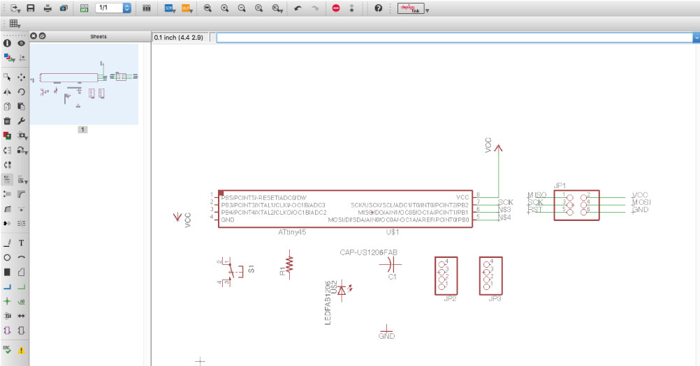
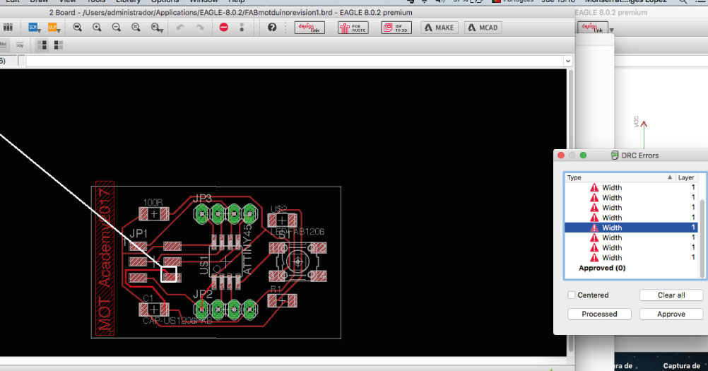
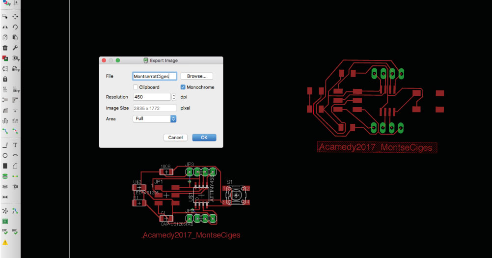
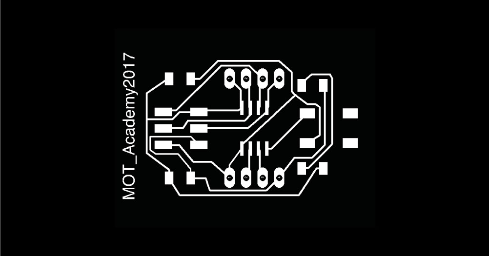
Desing in Eagle:
Using Autodesk Eagle, like in the asigment 4 I design the circuit board. I could make whit this software an schematic diagrams using the fab library I uploaded in the program library. When all the elements are in the screen, I have the final diagram to design the board and late I acomodate the elements in a optim distribution to routering the board later. I use the autoroute tool in eagle, to make a tracks but, sometimes in not the best idea, and appear some problems like in the picture, for my experience is better rearranged some tracks or do it without autoroute. When the design is ready, only I need the layer Top and Pads objects to export. The process is go to the menu, and export file like an image, in monocrome and whit 450 dpi resolution.
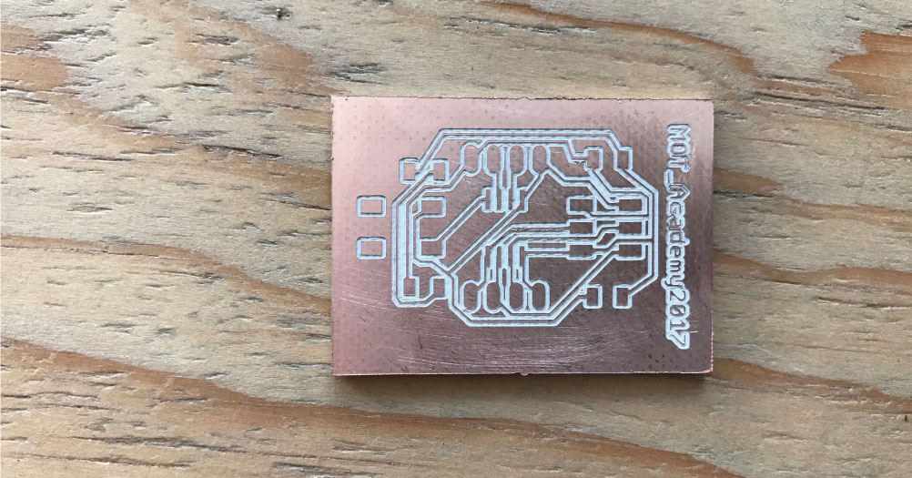
Cutting and welding:
It´s time to cut de board, and see the results. The board have a good results, but I have to drill the holes using the Dremel, like you you can see in the gift. Finally soldering all the components, to see the plate completely finished. I put masking tape so that it did not move at the time of soldering, after the assigmente 4, every time I have more skill with the cautin. This components are: 1 ATTiny 45 microcontroller/ 1 Capacitor 1uF/ 1 Reset button/ 1 Resistor 100 ohm/ 1 resistor 499 Ohm / 2x6 pin header/1 LED/
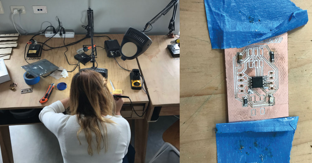
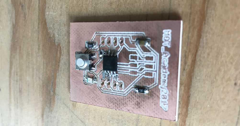
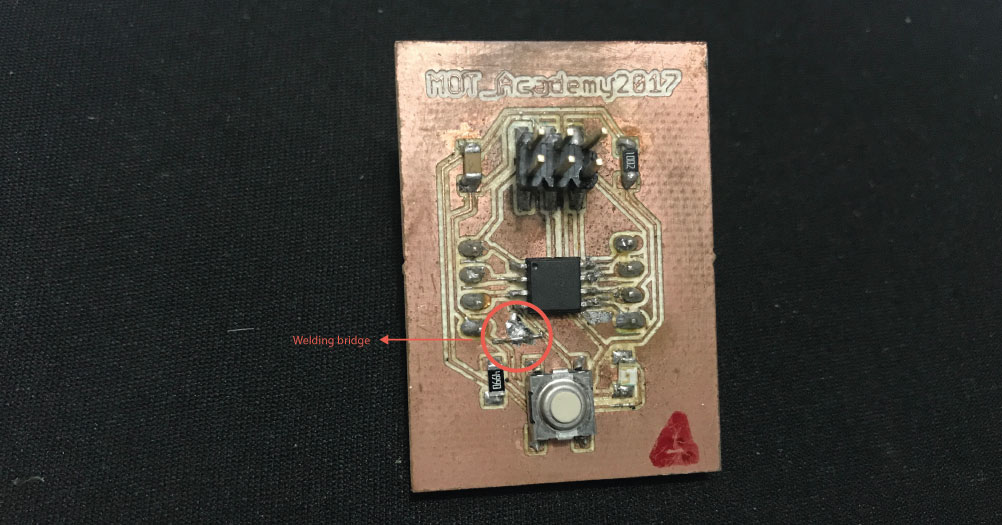
Failures:
After testing of the board, I realized that I had a failure on one of the tracks, so I had to improvise a bridge with a cable so it could function correctly. But Finally the board works!