Computer-controlled cutting
08_02 to 13_02 2017
Assignment:
1. Group assignment:
Make lasercutter test part(s), varying cutting settings and slot dimensions
2. Individual assignment: 2a.Cut something on the vinylcutter 2b.Design, make, and document a parametric press-fit construction kit, 2c.Accounting for the lasercutter kerf, which can be assembled in multiple ways
Academy files
03_Week work:
My goals for this week were two: On the one hand to learn the techniques of 3D modeling and design to perform the press-fit and kerft and on the other hand learn how to use the different laser cutting machines we have in the Fab Lab Veritas RedSail 1200x900 mm, CamFive 900x600. Each of them uses different software and has different operating modes.
Sofware:
Rhino, SmartCarve, coreldraw, lasermate 5.2.05, Sure Cuts A Lot Pro version 3.059
Machines:
RedSail 1200x900 mm, CamFive 900x600
Tutorials:
Tutorial 3
Drive files:
Download week work
Archive files:
cortevinil_mot.pdf / geometric_kerf.3dm
archive/work3/esfera.ghx
archive/work3/esfera.3dm
Assignment - furniture design from St. Jude Digital on Vimeo.
Group Assigment
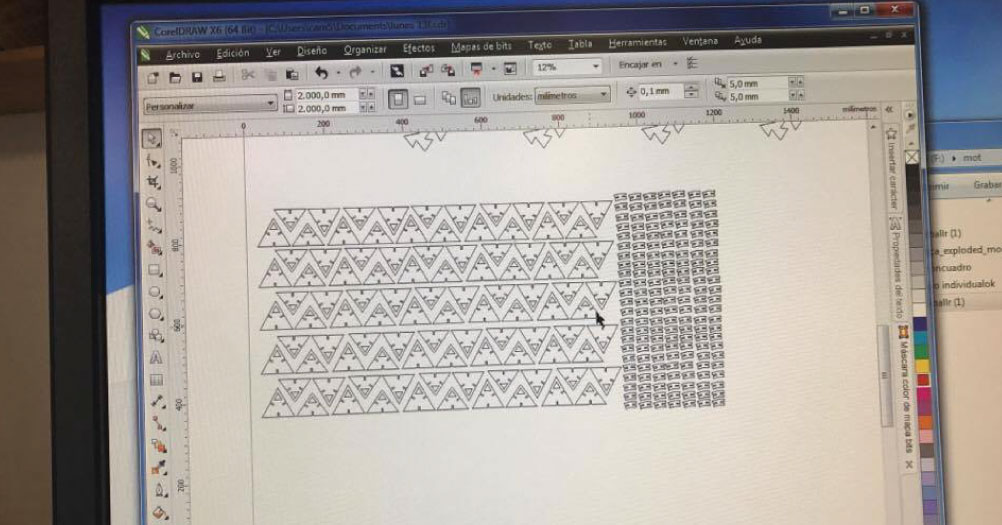
We use the laser cutter works with the software SmartCarve, and it accepts .plt files, so, we had to open a pdf or svg file with corelDRAW and export it to plt.
Then, the file is imported into SmartCarve, and the settings must be configured according to the material. For cardboard cutting the settings are:
Maximum power: 35 Minimum power: 30 Velocity: 30
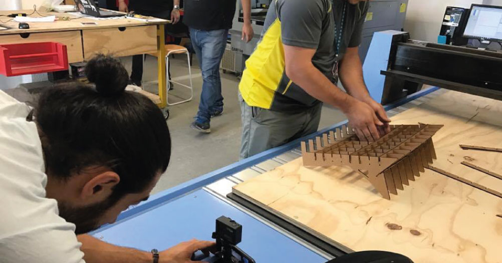
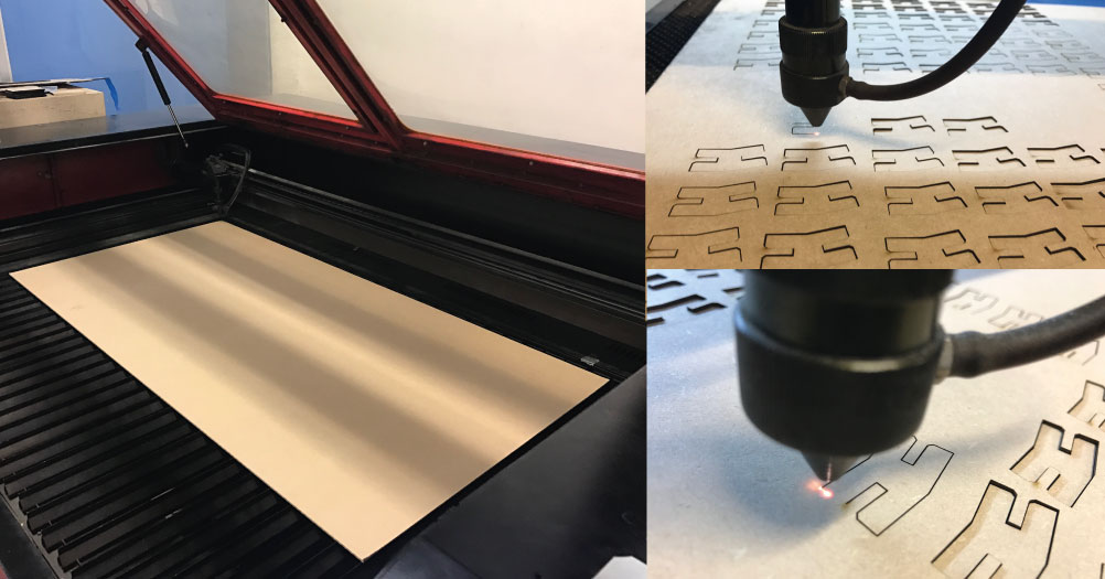
Then, we turned on the machine and set the height of the head to 6mm, and set the origin to one of the corners of the material. Once the cut is done, we assemble the pieces and obtain a piece of furniture for the computer.
Press-fit:
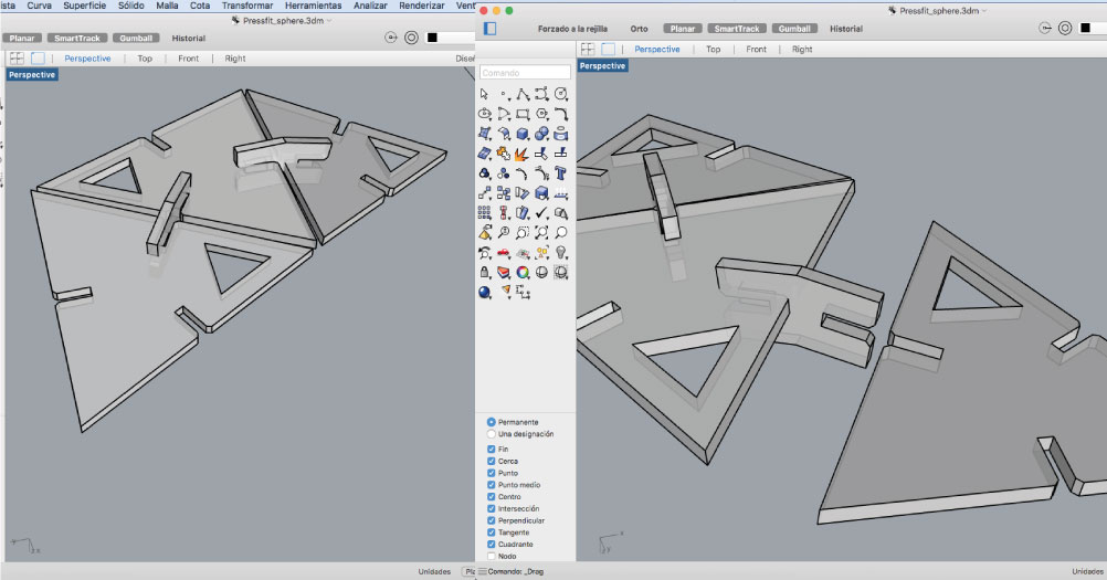
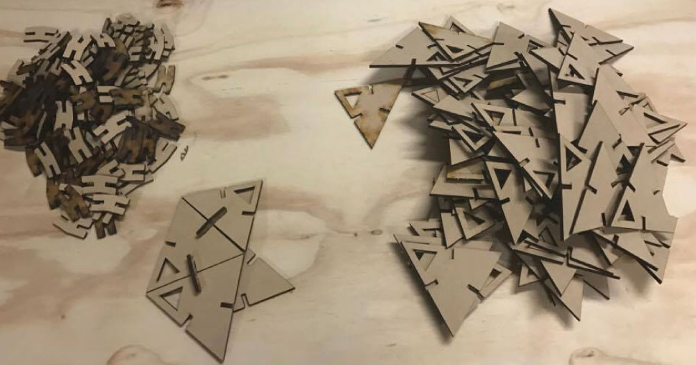
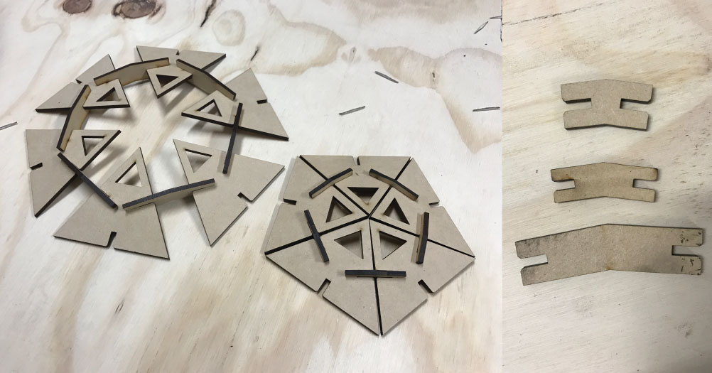
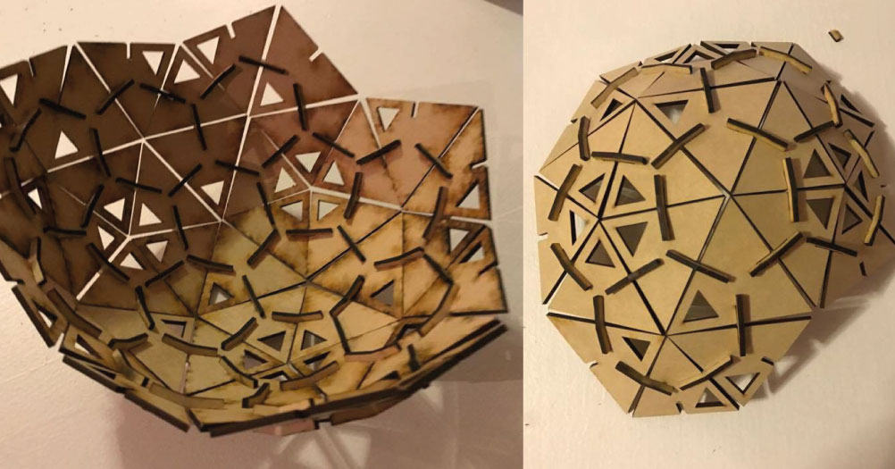
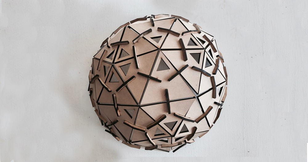
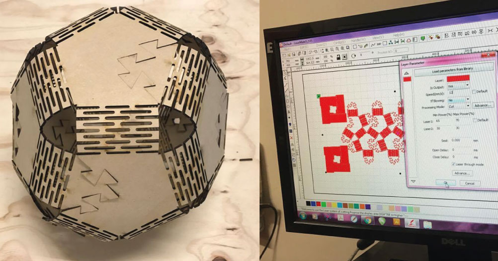
For the use of the presffit technique, I have made a module generate a sphere. The triangularization of the sphere is achieved by triangular pieces of various sizes, and the union through a piece with a 45 degree angle.
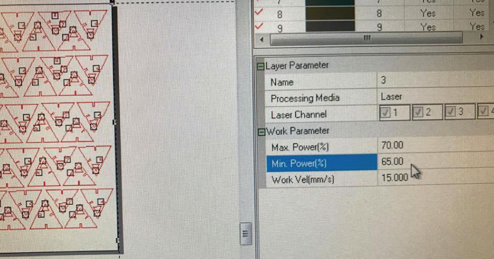
I had to design the pieces with 3mm thickness in their joints, since that was the thickness of the Mdf, material that used for its realization. configured the settings according with this material, mdf 3mm. The cutting the settings are: Maximum power: 70 Minimum power: 65 Velocity: 15
Failures:
I had problems with one of the pieces, because the measurement was not correct to be able to generate a closed sphere. I had to design the same piece several times to finally get the right size.
The pieces are designed with a small angle on the tips for easy assembly.
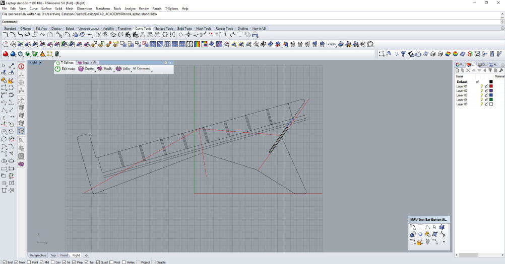
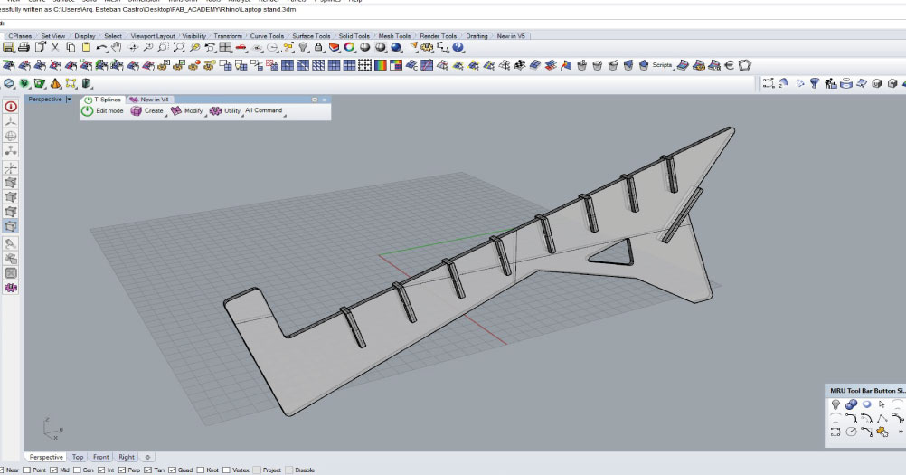
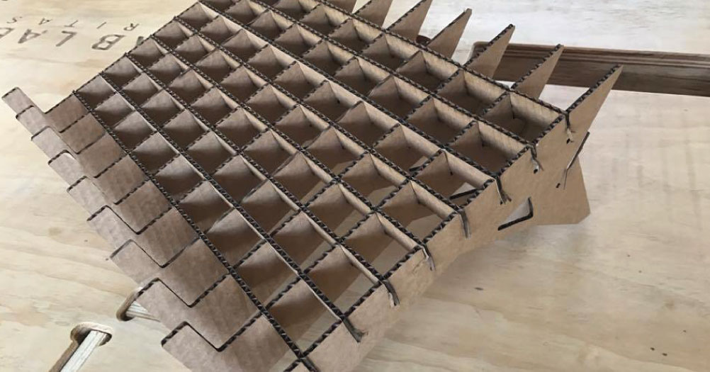
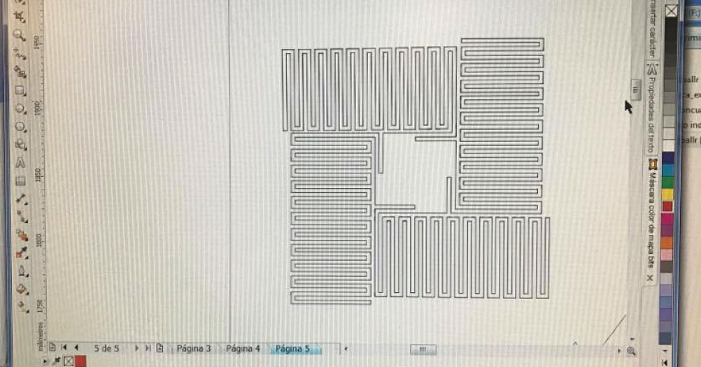
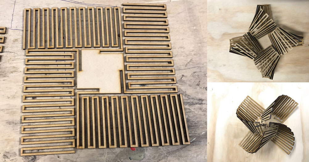
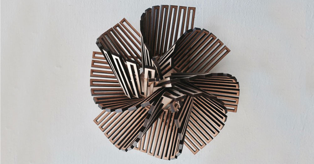
Flexural joint:
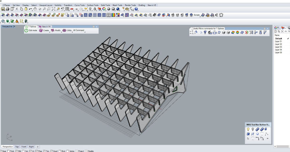
To design this piece I used the software Rhinoceros, which allowed me to repeat the parts of the piece and the separation indicated between them so that the wood could be folded. For use the kerf technique, I design this geometric piece with the possibility of joining it in several positions. When creating the frame, I defined a separation between lines of 3mm due to the Mdf material, which I was going to use, but at the end I realized that this distance was not necessary in this case, since there is no union, the cuts are for Generate the flexibility of the material.
I configured the settings according with this material, mdf 3mm. The cutting the settings are:
Maximum power: 55 Minimum power: 50 Velocity: 12
VinylCutter:
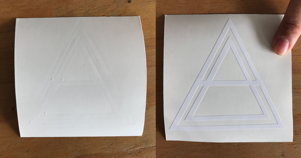
I made in adobe ilustrator my own logo, and I exported the file in PDF format.
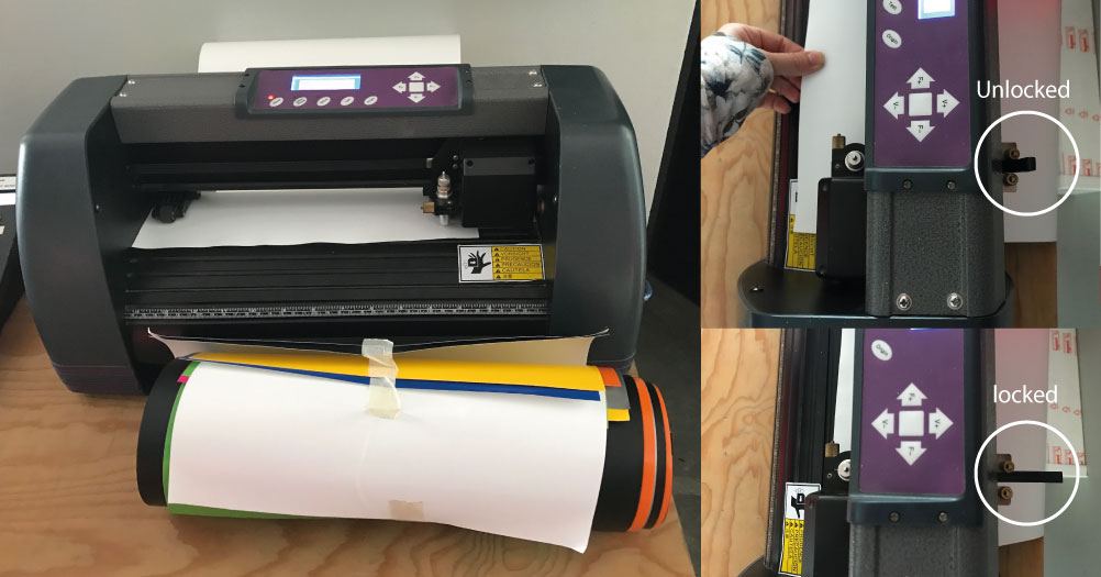
I prepared the machine, inserting the vinyl paper. You must be carefull with the unlocked sistem to insert and fixe the vinyl in the machine. Now the machine its ready for cut.
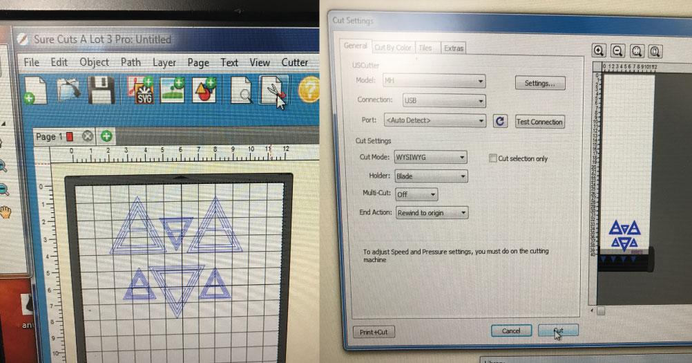
In the Fab Lab computer I use Sure Cuts A Lot Pro version 3.059, and I imported the Pdf File to this software. The process is so simple, just adjust the image and press the Cut with Cutter button for start to cut.
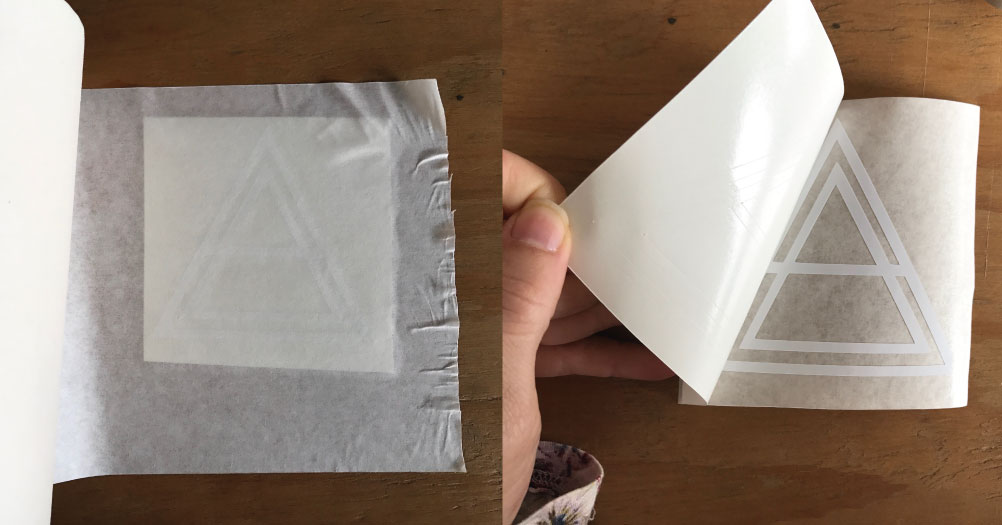
Once you have the vinyl cut, and removing leftover material, it´s time to transfer the sticker with a transfer paper, and like in the pictures, take out the sticker paper, when you want paste in some place.
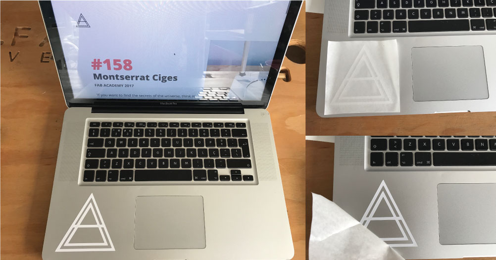
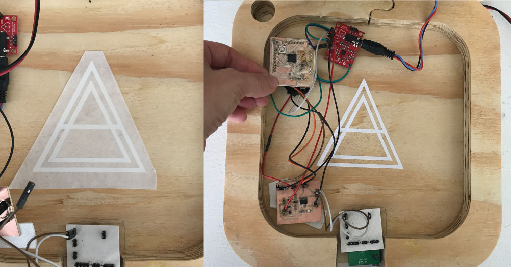
I chose my computer, to recognise my computer of the other, because in the class everybody have the same Mac. I used the sticker too for my final project inside of the box, like my personal brand.
Parametric:
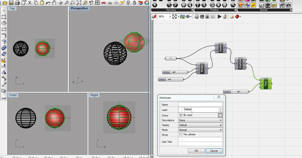
I used the Grasshopper Rhinoceros plugin for the parametric design part, since last year I did a basic course and it was the most familiar program for me. For this I have seen different trades to be able to remember its operation. The tutorial is basic level, and the goal was to make a sphere, with axes that can be modified by the number slides.
First realize a sphere in rhinoceros, that activates in Grasshopper with a surface. Add the formula to divide and I could already see how the sphere was making changes.
The two screens must be open to be able to visualize the actions that are being performed in the grasshoper.
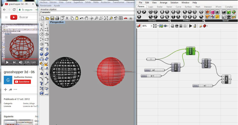
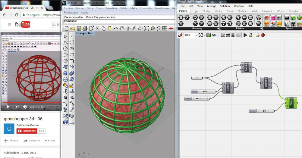
Following the turorial, I performed all the steps that led me to obtain the structure of the spheres.
The final step is bake, to generate a solid with the parameters selected for that object.
This program facilitates you to modify the parameters of the object without having to re-design it, which greatly facilitates the industrial design.
This formula was very basic, but I have to admit that this program makes me complicated to enterder all its functions.