Week 4: Electronics production
Experience: Diagraming the FabISP
Objetive:
Make an in-circuit programmer by milling the PCBLinks:
http://fab.cba.mit.edu/content/projects/fabisp http://www.autodesk.com/products/eagle/overviewResources:
PDF FabISP diagram LBR Fab components library SCH my schematic FabISP diagram BRD my board FabISP diagram SCH MIT schematic FabISP diagram BRD MIT board FabISP diagram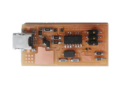
FabISP
This week we learn how to diagram our own FabISP on Eagle software
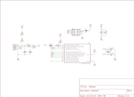
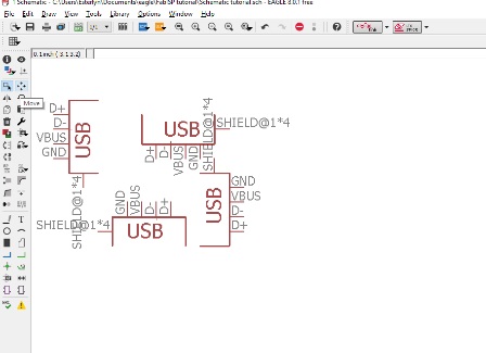
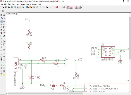
FabISP diagram
This is the FabISP diagram we replicate
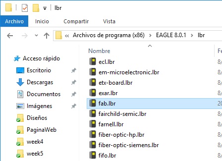
Fab library
To include the Fab library with all the necesary components, I download and copy fab.lbr in "C:\Program Files (x86)\EAGLE 8.0.1\lbr"

Eagle software
For the exercise we use Eagle
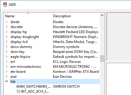
The Fab library
If the Fab library is in the right place, it will appear as in the image
Using the mouse
We can rotate objects with mouse right button and put it with left click
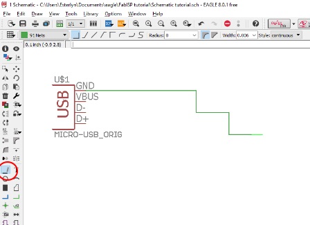
Lines
The Line button permits to join elements
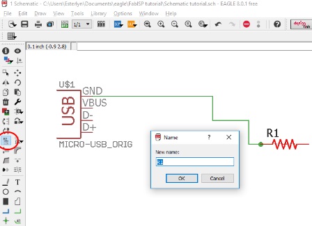
Names
To rename elements we use the Name button
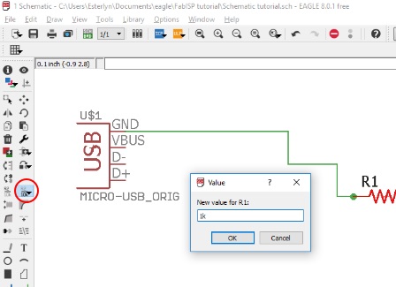
Values
To change the values use the Value button
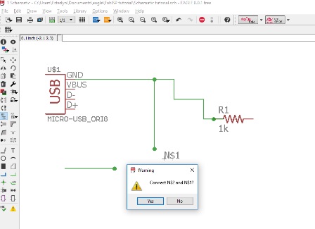
Junction
The junction button permits to join elements without a line, this is useful for a better diagram view
The work continues
Basically with the previous commands we are capable of to continue duplicating the FabISP diagram
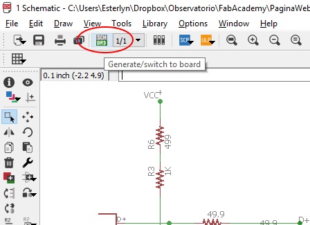
Diagraming the board
Once finished the electric diagram, we can work in the board design, for this use the Generate/switch to board button
Creating routes
We try to accommodate the components in the best way, so that the lines do not cross each other
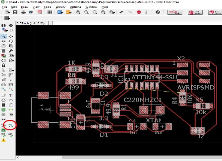
Autoroute
You can trace the routes manually or with the Autorute button. The goal is that 100% of the connections have a logical and physical route. This process can be improved with constant practice
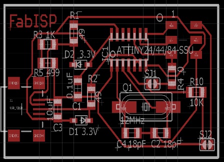
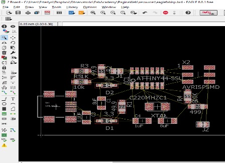
FabISB board
This is the working FabISP board, it is available for download on the internet
Experience: Cutting the FabISP
Objetive:
Make an in-circuit programmer by milling the PCBLinks:
https://othermachine.co/support/pcb/gerber-filesResources:
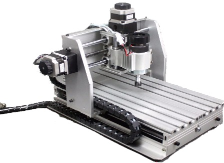
Knowing the machine
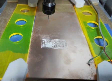
For cut the board we use the 3020T Mini CNC engraving machine
Technnical details
Maximum working stroke: XYZ = 200 * 300 * 45mm, overall dimensions: 520 × 400 × 370mm, working table size: 440 × 240mm, Engraving speed: 300-3000mm / min, control communication interface: 25-pin parallel port, control software: MACH3, tool path format: G code / .nc / .ncc / .tab / .txt
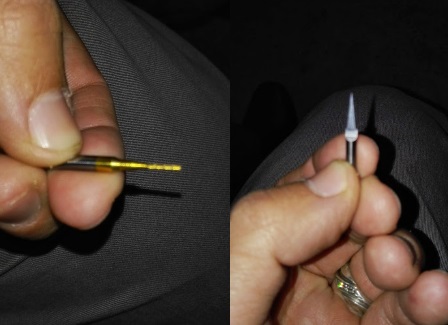
Drills
Two types of drill were used
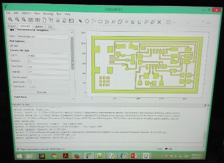
sol file
3 files are necesary for to complete the cut task, the first is the top traces (.sol), that describes the shape of the traces and pads on the top side of the PCB. The bottom traces is an optional files if your PCB is one-sided, but necesary if is dual-sided
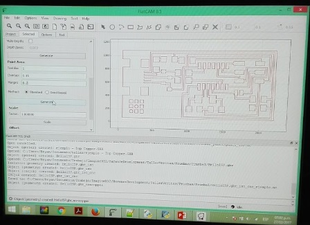
plc file
The second is the outline (.plc), that describes the outer dimension of the board
drb file
The third is for the holes (.drd), that describes the location and size of the PCB’s holes and vias
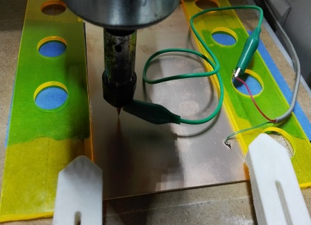
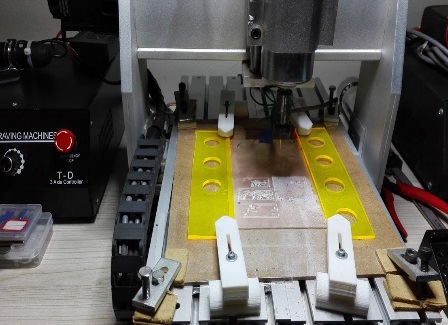
Preparing the plate
The plate is held by means of presses and is also supported by blue masking tape. For this machine can be made a measurement of the height of different points of the surface using an electrical contact
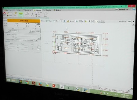
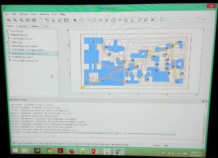
Using the files
Once the plate is clamped and aligned, a software called bCNC is used, which interprets the previously created files and sends the gcode to the machine
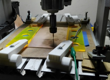
And the cut begins
For security reasons is important to use protective glasses and dont touch the plate while the machine is cutting
The cut continues
In this case, the entire process can take about 30 minutes
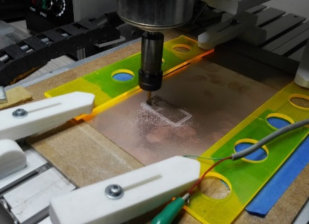
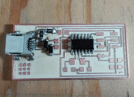
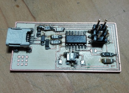
Almost ready
We can clearly notice the cuts made to the plate and the strokes on the surface
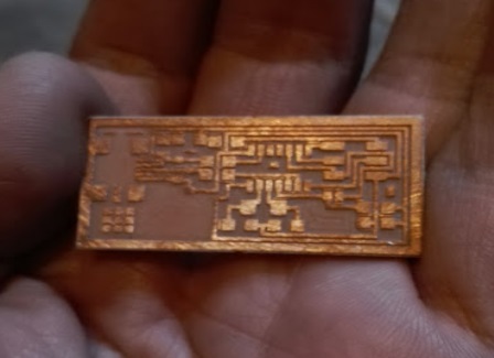
The result
We are ready to solder the electronic components
Experience: Soldering then components
Objetive:
Make an in-circuit programmer by milling the PCBLinks:
http://fabacademy.org/archives/2014/students/garita.robert/5.ElectronicsProduction.html https://www.arduino.cc/en/Main/Software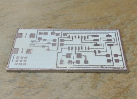
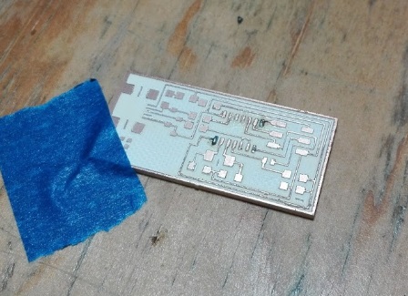
Ready to solder
This is the board clean and ready to solder, we cut an additional one in case of damaging the first
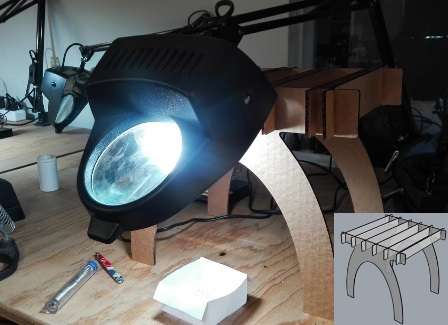
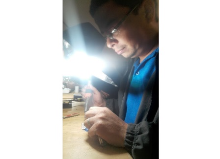
Preparing the tools
Because the lamp with a magnifying glass was broken, I decided to support it in the bench we made in assignment 3, so we can say that we truly use it :)
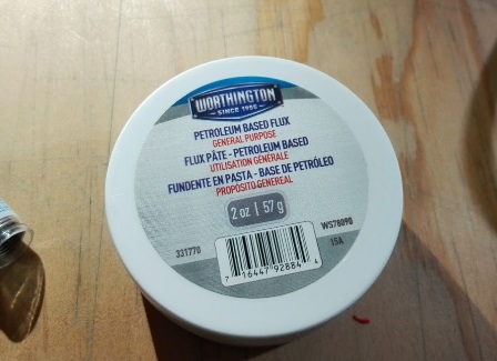
Do not forget to have this
We use petroleum based flux for clean the surfaces and that the solder be distributed properly
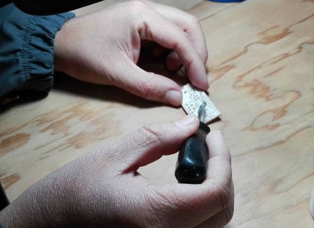
Putting fluxing
We put some fluxing in the place where we going to solder with a fine point tool
Putting solder
Then we put some solder, just a little
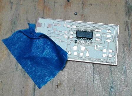
Soldering the microprocesor
Put the microprocessor and heat the joints, when it sticks to the solder we put a little more on
Patience is success
With great care and patience we continue to soldering the remaining joints of the microprocessor
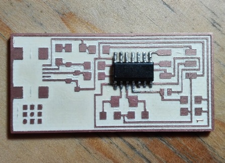
First piece ready
Now that we have putted the first piece it is time to test the connections
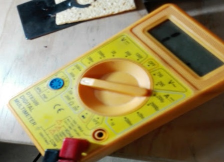
Testing connections
To test the connections we have testers, specifically we use it to measure continuity
Connections okay
Fortunately all connections were well soldering
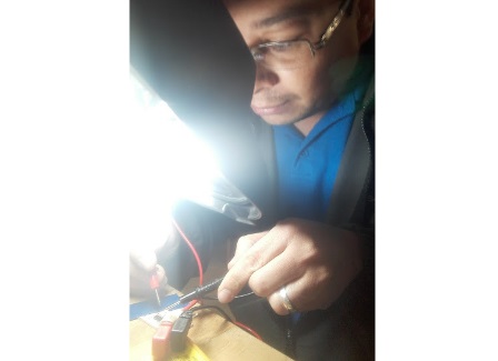
Soldering more parts
Now that we have more self-confidence, we continue to weld more parts, such as usb connector, zener diodes and resistors
More resistors
We soldering a couple more resistors
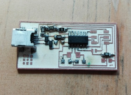
Correcting an error
Because the crystal we bought was different, since it has the 2 necessary capacitors integrated, the plate tracks did not work. This forced us to make a correction using the cutter
Crystal worked well
Luckily the correction was simply dividing two of the tracks and the improvised solution worked perfectly
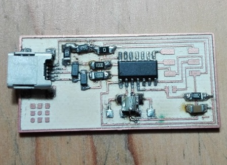
Pin headers
We put the pin headers and we are almost ready to program the board
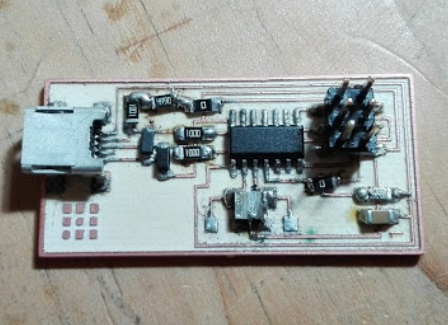
Board ready
When putting the last resistance we are ready to test the board
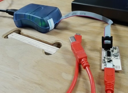
First successful test
The green light on the programmer came on indicating that the board had no errors
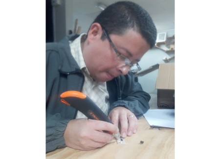
Great help
With the help of Cesar Cruz, a Peruvian, expert in electronics and who will be in the country for some months, we started downloading the drivers of the programmer for Ubuntu
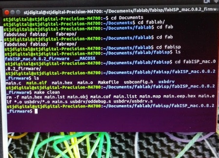
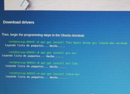
Initializing the board
We start programming by initializing the board and then copying the firmware
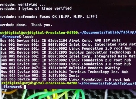
Programming was success
We can see in the summary that the board was detected as USBtiny
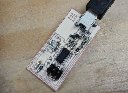
Ready for programming
The board is ready to program, we will do this in the next assignments
Powered by w3.css