


week 4
Electronics Production
Assignment:
make an in-circuit programmer by milling the PCB, then optionally trying other processes.
make an in-circuit programmer by milling the PCB, then optionally trying other processes.
Guillermo Jaramillo :: Fab Academy 2017
Fab Academy 2017

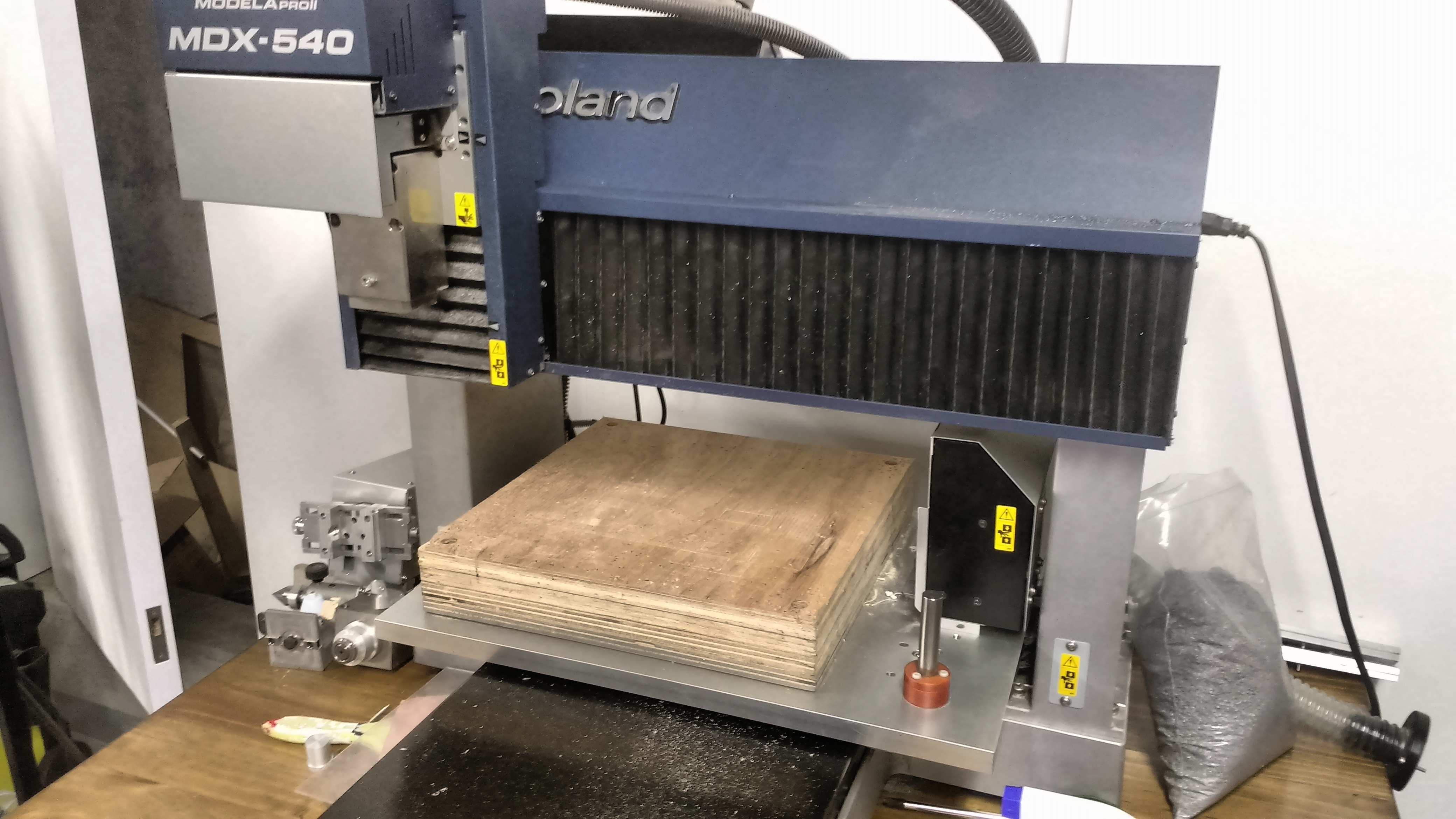
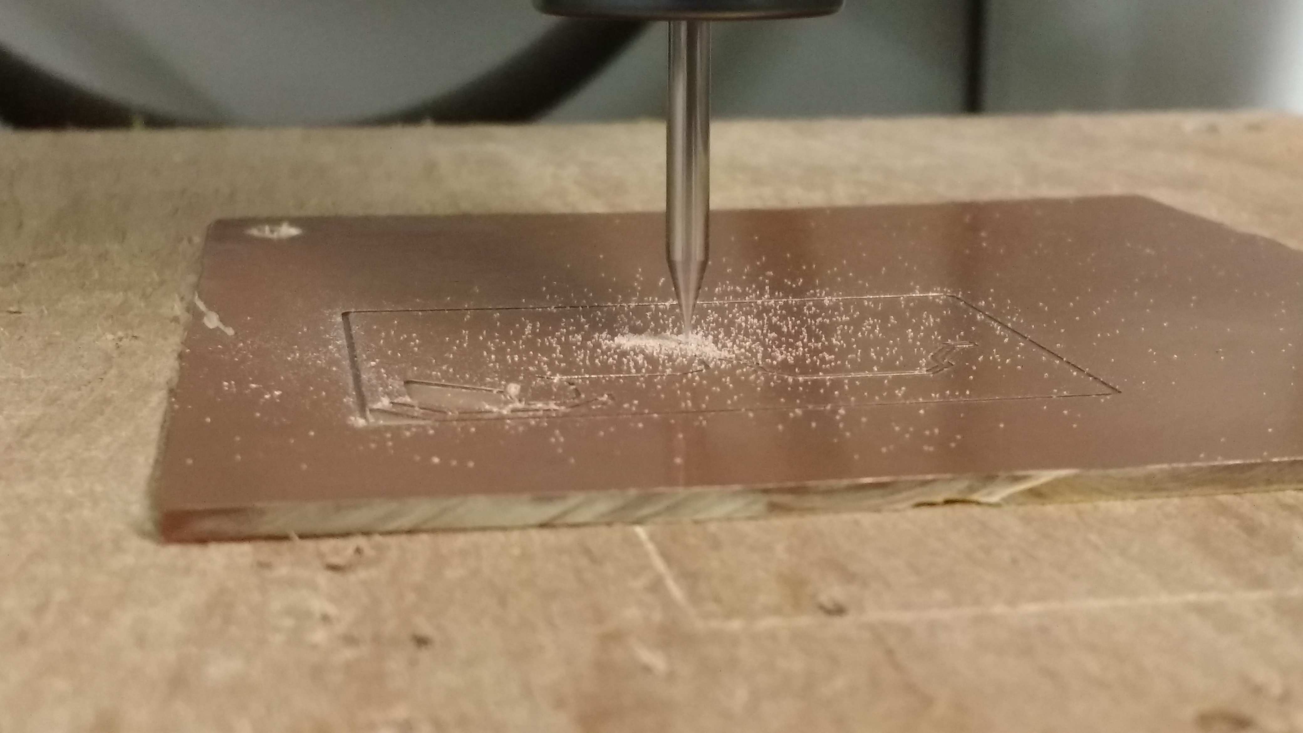
The first process to do is prepare the milling machine to produce the board. In our Fab at UTEC, we have a Modela MDX540 to do the job.
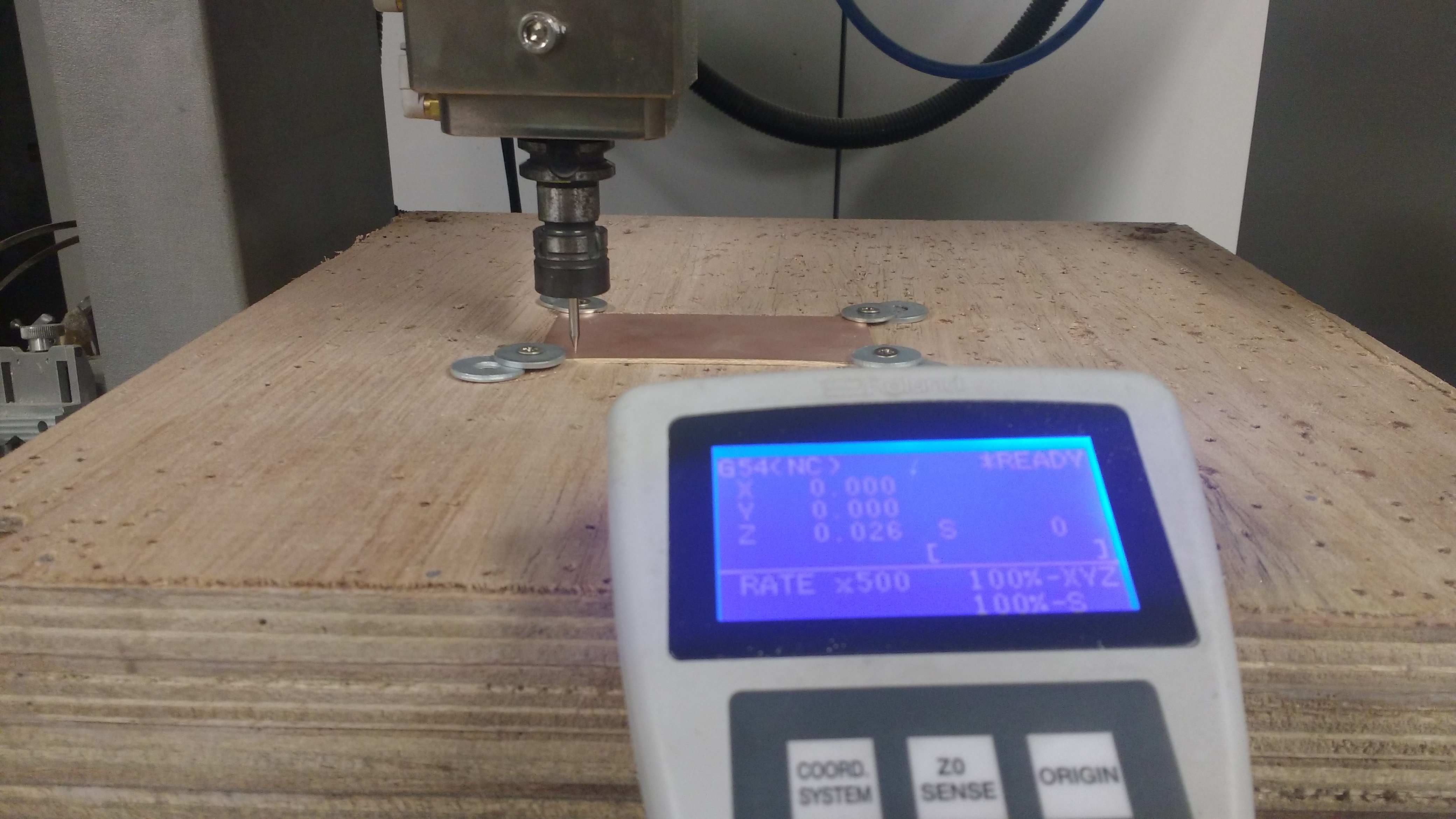
So the process start with the PCB fixation using screws at the sacrify bed. As next step its necessary setting the coordinates system in the milling machine. This process is called Zero Setting (x, y, z), because the modela is a cartesian three axis machine.
So the process start with the PCB fixation using screws at the sacrify bed. As next step its necessary setting the coordinates system in the milling machine. This process is called Zero Setting (x, y, z), because the modela is a cartesian three axis machine.
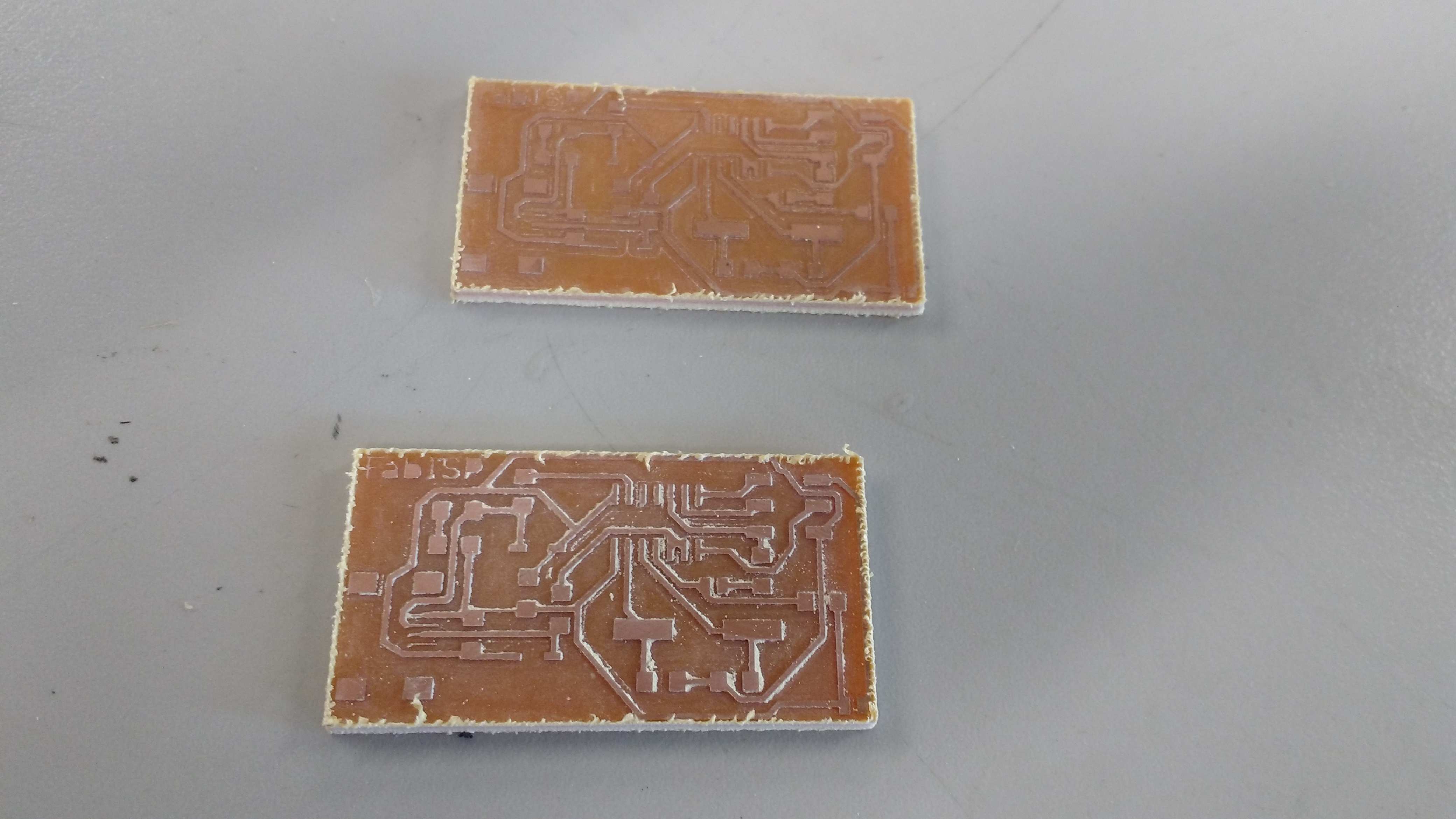
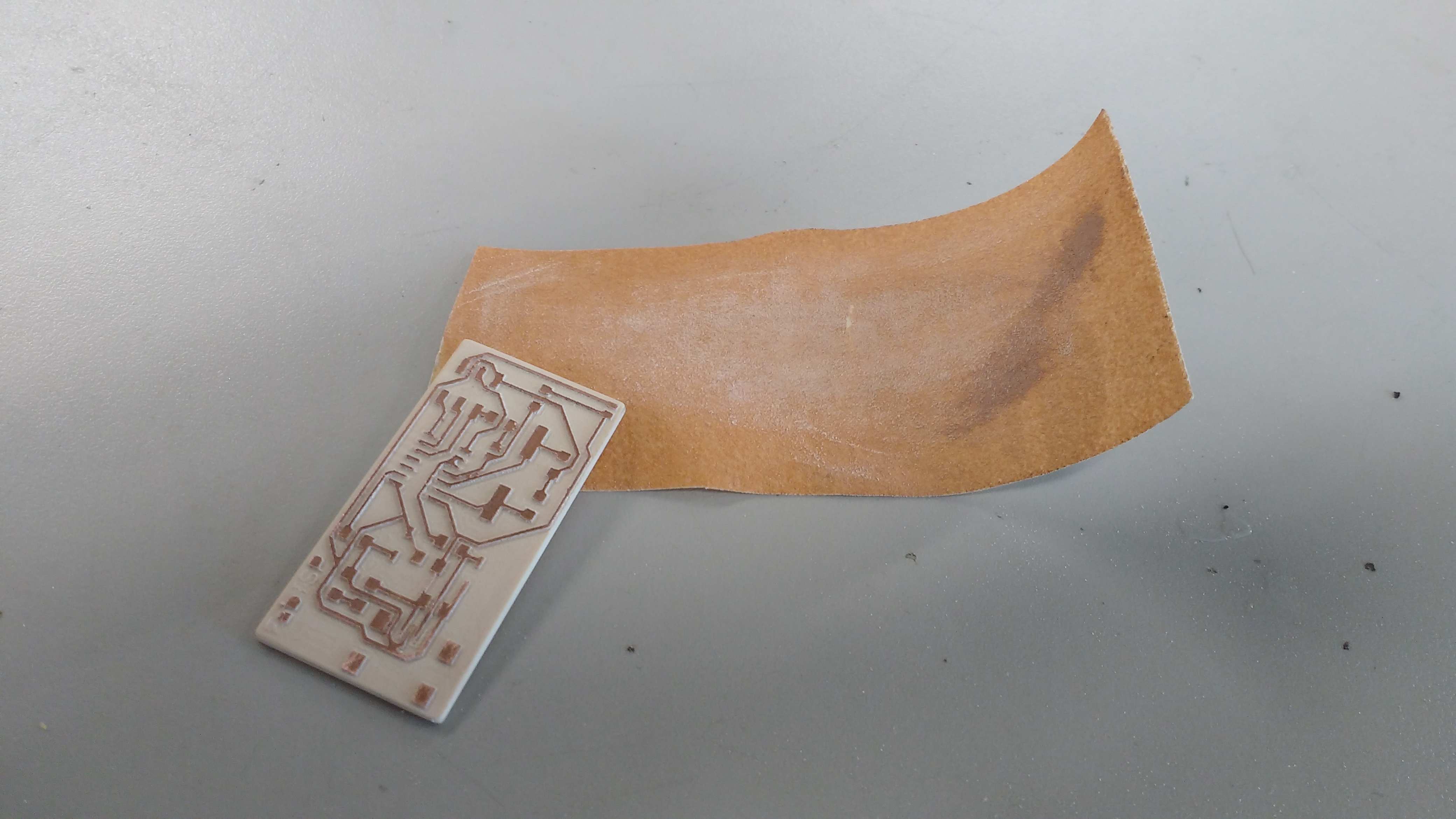
Once the milling job of the board is finished, its time to prepair the board to soldering the components on it. The process is totaly new for me because I have sso much experience with through hole but never with surface mounting. I prepare a set of boards using FR1 and FR2 to have ever a backup board if any one falis. Its necessary to sand the board to clean the coopper surface.
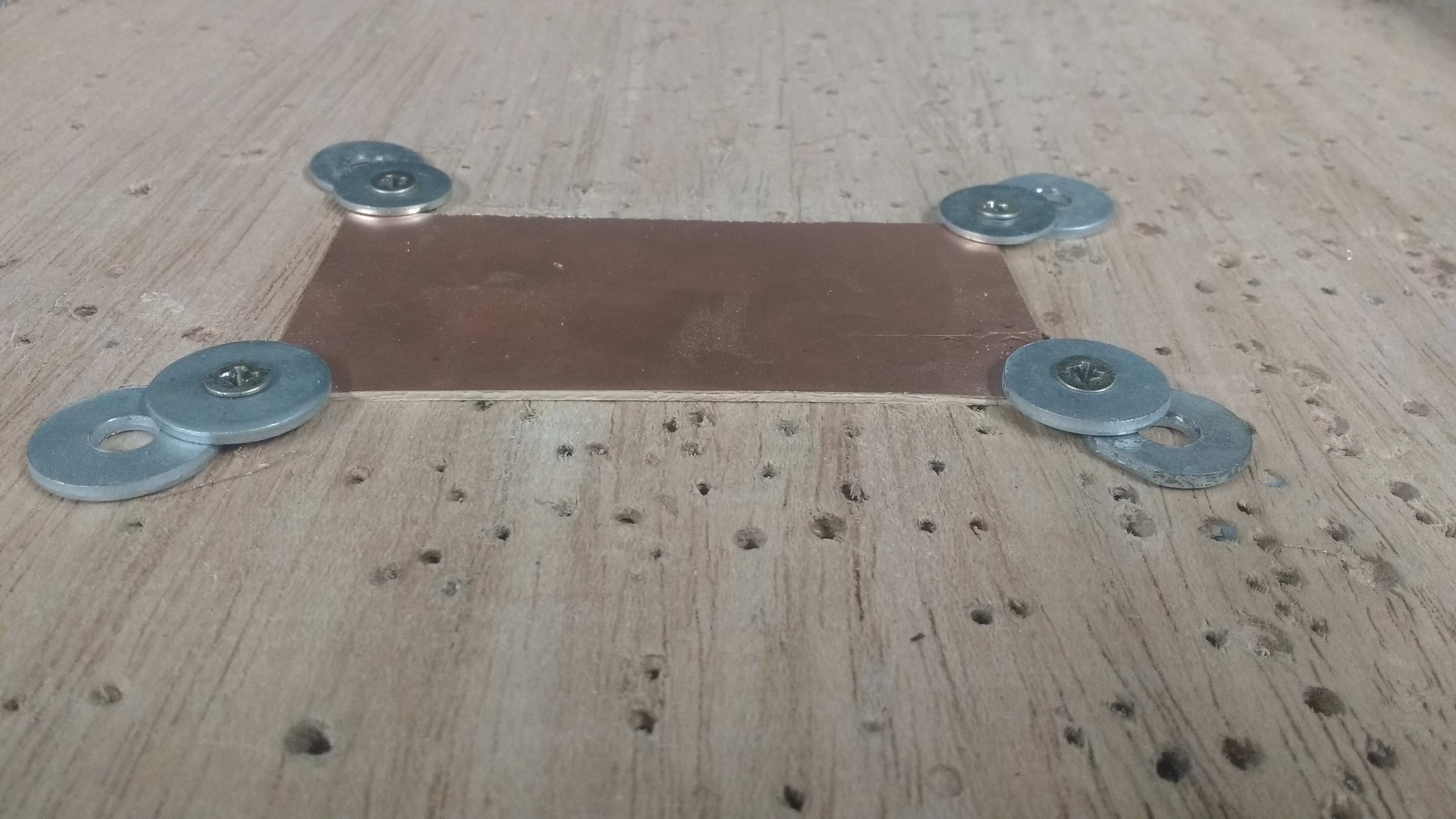
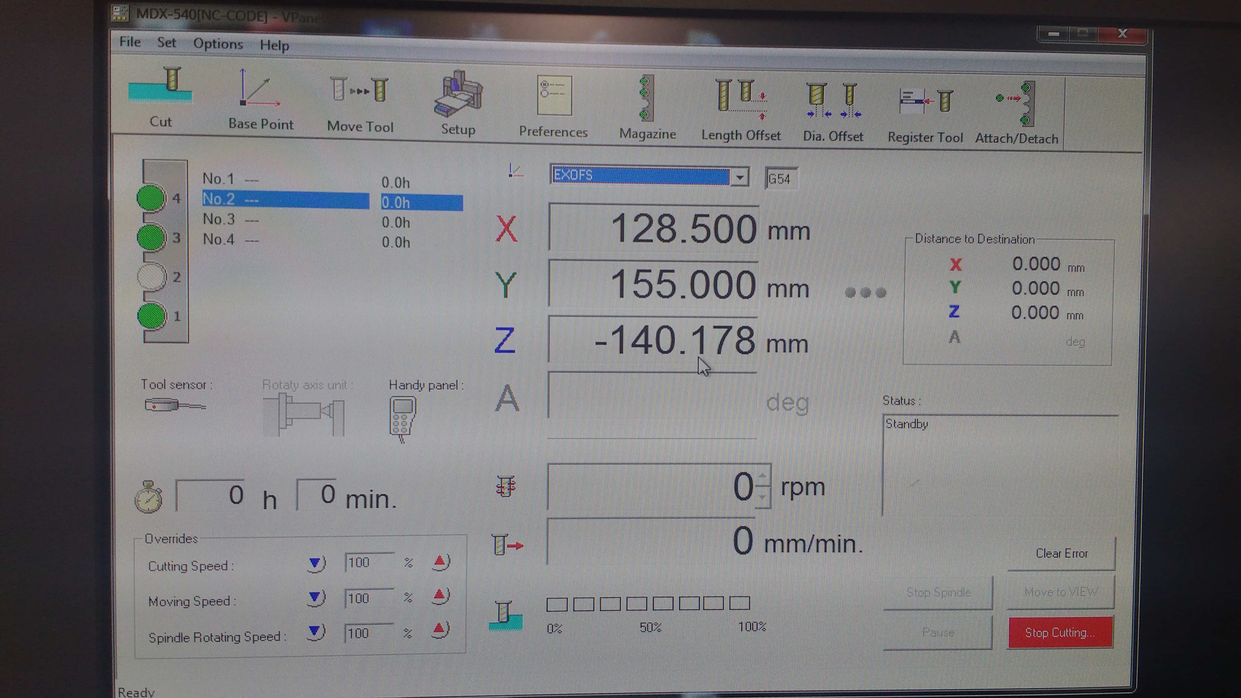
The next step is start the milling process using a software to translate G code to the modela. And load the G code to start the milling job. The board can be fixed using screws or double sided adhesive tape as shown in the picture.
nemo@NEMOSTATION:~/Downloads/fabISP_mac.0.8.2_firmware $ make clean
rm -f main.hex main.lst main.obj main.cof main.list main.map main.eep.hex main.elf *.o usbdrv/*.o main.s usbdrv/oddebug.s usbdrv/usbdrv.s
nemo@NEMOSTATION:~/Downloads/fabISP_mac.0.8.2_firmware $ make hex
avr-gcc -Wall -Os -DF_CPU=12000000
-Iusbdrv -I. -DDEBUG_LEVEL=0 -mmcu=attiny44 -c usbdrv/usbdrv.c -o usbdrv/usbdrv.o
avr-gcc -Wall -Os -DF_CPU=12000000
-Iusbdrv -I. -DDEBUG_LEVEL=0 -mmcu=attiny44 -x assembler-with-cpp -c usbdrv/usbdrvasm.S -o usbdrv/usbdrvasm.o
avr-gcc -Wall -Os -DF_CPU=12000000
-Iusbdrv -I. -DDEBUG_LEVEL=0 -mmcu=attiny44 -c usbdrv/oddebug.c -o usbdrv/oddebug.o
avr-gcc -Wall -Os -DF_CPU=12000000
-Iusbdrv -I. -DDEBUG_LEVEL=0 -mmcu=attiny44 -c main.c -o main.o
main.c:88:13: warning: always_inline function might not be inlinable [-Wattributes]
static void delay ( void )
^
avr-gcc -Wall -Os -DF_CPU=12000000
-Iusbdrv -I. -DDEBUG_LEVEL=0 -mmcu=attiny44 -o main.elf usbdrv/usbdrv.o usbdrv/usbdrvasm.o usbdrv/oddebug.o main.o
rm -f main.hex main.eep.hex
avr-objcopy -j .text -j .data -O ihex main.elf main.hex
avr-size main.hex
text data
bss dec
hex filename
0 2070
0 2070
816 main.hex
nemo@NEMOSTATION:~/Downloads/fabISP_mac.0.8.2_firmware $ make fuse
avrdude -c avrispmkii -P usb -p attiny44 -U hfuse:w:0xDF:m -U lfuse:w:0xFF:m
avrdude: AVR device initialized and ready to accept instructions
Reading | ################################################## | 100% 0.00s
avrdude: Device signature = 0x1e9207
avrdude: reading input file "0xDF"
avrdude: writing hfuse (1 bytes):
Writing | ################################################## | 100% 0.00s
avrdude: 1 bytes of hfuse written
avrdude: verifying hfuse memory against 0xDF:
avrdude: load data hfuse data from input file 0xDF:
avrdude: input file 0xDF contains 1 bytes
avrdude: reading on-chip hfuse data:
Reading | ################################################## | 100% 0.00s
avrdude: verifying ...
avrdude: 1 bytes of hfuse verified
avrdude: reading input file "0xFF"
avrdude: writing lfuse (1 bytes):
Writing | ################################################## | 100% 0.00s
avrdude: 1 bytes of lfuse written
avrdude: verifying lfuse memory against 0xFF:
avrdude: load data lfuse data from input file 0xFF:
avrdude: input file 0xFF contains 1 bytes
avrdude: reading on-chip lfuse data:
Reading | ################################################## | 100% 0.00s
avrdude: verifying ...
avrdude: 1 bytes of lfuse verified
avrdude: safemode: Verify error - unable to read hfuse properly. Programmer may not be reliable.
avrdude: safemode: Fuses OK (H:FF, E:DF, L:FF)
avrdude done. Thank you.
nemo@NEMOSTATION:~/Downloads/fabISP_mac.0.8.2_firmware $ make program
avrdude -c avrispmkii -P usb -p attiny44 -U flash:w:main.hex:i
avrdude: AVR device initialized and ready to accept instructions
Reading | ################################################## | 100% 0.00s
avrdude: Device signature = 0x1e9207
avrdude: NOTE: "flash" memory has been specified, an erase cycle will be performed
To disable this feature, specify the -D option.
avrdude: erasing chip
avrdude: reading input file "main.hex"
avrdude: writing flash (2070 bytes):
Writing | ################################################## | 100% 0.72s
avrdude: 2070 bytes of flash written
avrdude: verifying flash memory against main.hex:
avrdude: load data flash data from input file main.hex:
avrdude: input file main.hex contains 2070 bytes
avrdude: reading on-chip flash data:
Reading | ################################################## | 100% 0.65s
avrdude: verifying ...
avrdude: 2070 bytes of flash verified
avrdude: safemode: Fuses OK (H:FF, E:DF, L:FF)
avrdude done. Thank you.
avrdude -c avrispmkii -P usb -p attiny44 -U hfuse:w:0xDF:m -U lfuse:w:0xFF:m
avrdude: AVR device initialized and ready to accept instructions
Reading | ################################################## | 100% 0.00s
avrdude: Device signature = 0x1e9207
avrdude: reading input file "0xDF"
avrdude: writing hfuse (1 bytes):
Writing | ################################################## | 100% 0.00s
avrdude: 1 bytes of hfuse written
avrdude: verifying hfuse memory against 0xDF:
avrdude: load data hfuse data from input file 0xDF:
avrdude: input file 0xDF contains 1 bytes
avrdude: reading on-chip hfuse data:
Reading | ################################################## | 100% 0.00s
avrdude: verifying ...
avrdude: 1 bytes of hfuse verified
avrdude: reading input file "0xFF"
avrdude: writing lfuse (1 bytes):
Writing | ################################################## | 100% 0.00s
avrdude: 1 bytes of lfuse written
avrdude: verifying lfuse memory against 0xFF:
avrdude: load data lfuse data from input file 0xFF:
avrdude: input file 0xFF contains 1 bytes
avrdude: reading on-chip lfuse data:
Reading | ################################################## | 100% 0.00s
avrdude: verifying ...
avrdude: 1 bytes of lfuse verified
avrdude: safemode: Fuses OK (H:FF, E:DF, L:FF)
avrdude done. Thank you.
The BIM to prepare the board is:
* 01 jack USB mini
* 01 1k ohm resistor
* 01 10k ohm resistor
* 01 499 ohm resistor
* 02 49 ohm resistor
* 02 3.3v zener diode
* 01 10uF condenser
* 01 0.1uF condenser
* 01 0 ohm resistor
* 01 20 MHz crystal
* 02 18 pF condenser
* 01 2x3 jumper pinheader
* 01 AtTiny 44 microcontroller
* 01 jack USB mini
* 01 1k ohm resistor
* 01 10k ohm resistor
* 01 499 ohm resistor
* 02 49 ohm resistor
* 02 3.3v zener diode
* 01 10uF condenser
* 01 0.1uF condenser
* 01 0 ohm resistor
* 01 20 MHz crystal
* 02 18 pF condenser
* 01 2x3 jumper pinheader
* 01 AtTiny 44 microcontroller
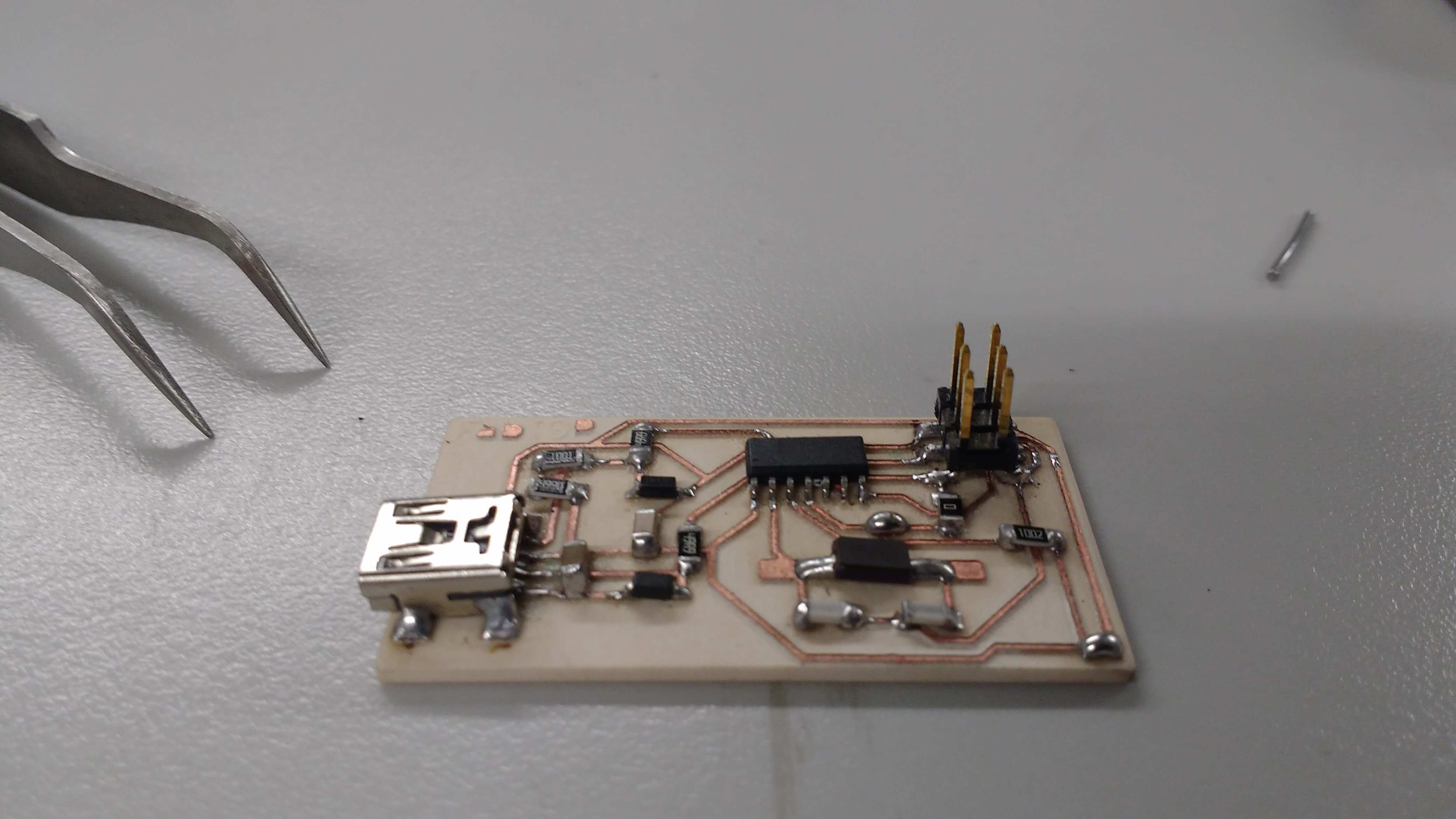
The process to solder the components needs this list of tools and materials:
* An iron soldering tool.
* Metal welding tongs.
* Tin alloy 50/50.
* Magnifying glass.
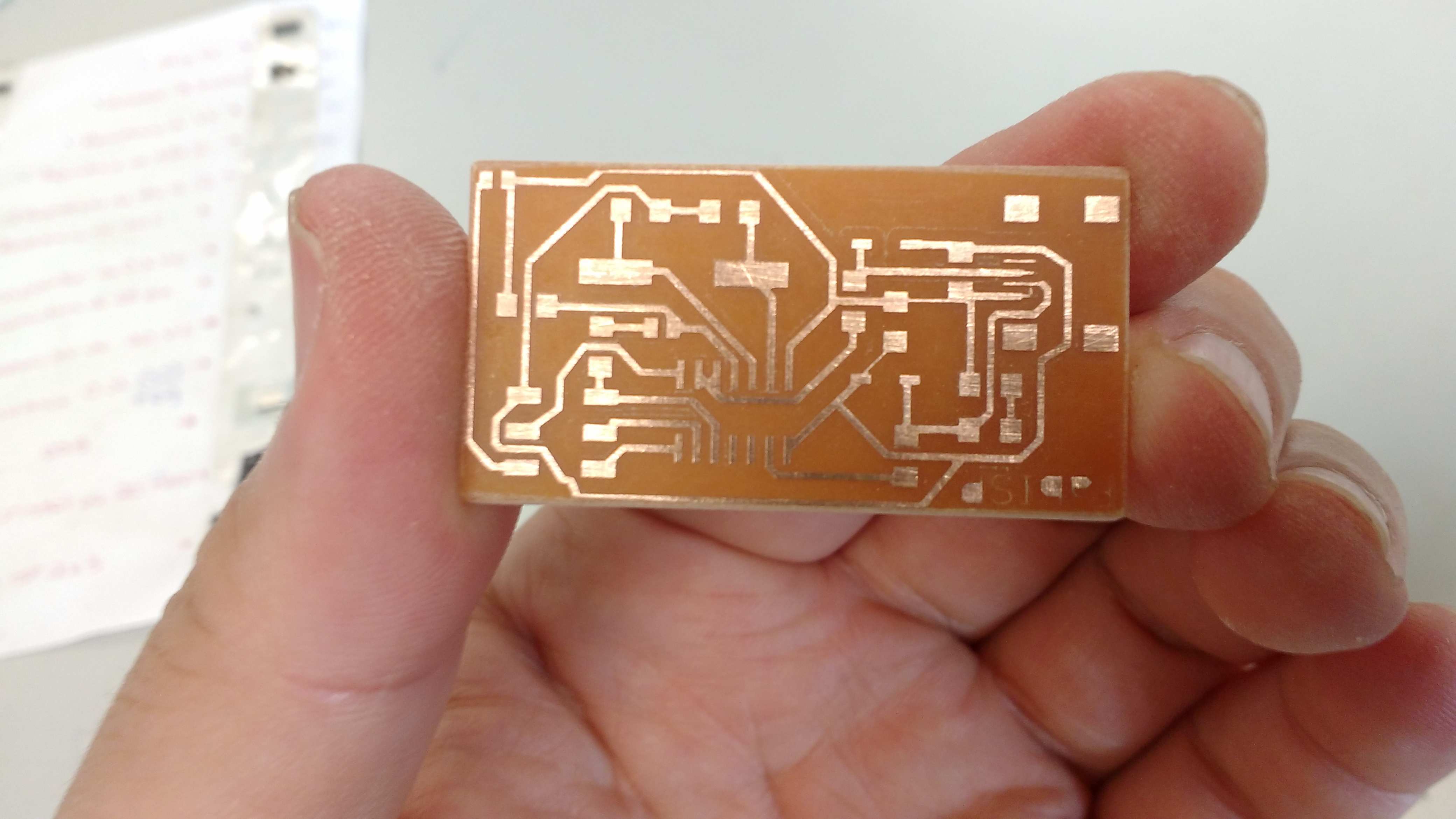
Once the componentes are solded in the board is looks like this.
The next step is to program the new board using the Fab ISP and excuting some commands.
* An iron soldering tool.
* Metal welding tongs.
* Tin alloy 50/50.
* Magnifying glass.
Once the componentes are solded in the board is looks like this.
The next step is to program the new board using the Fab ISP and excuting some commands.
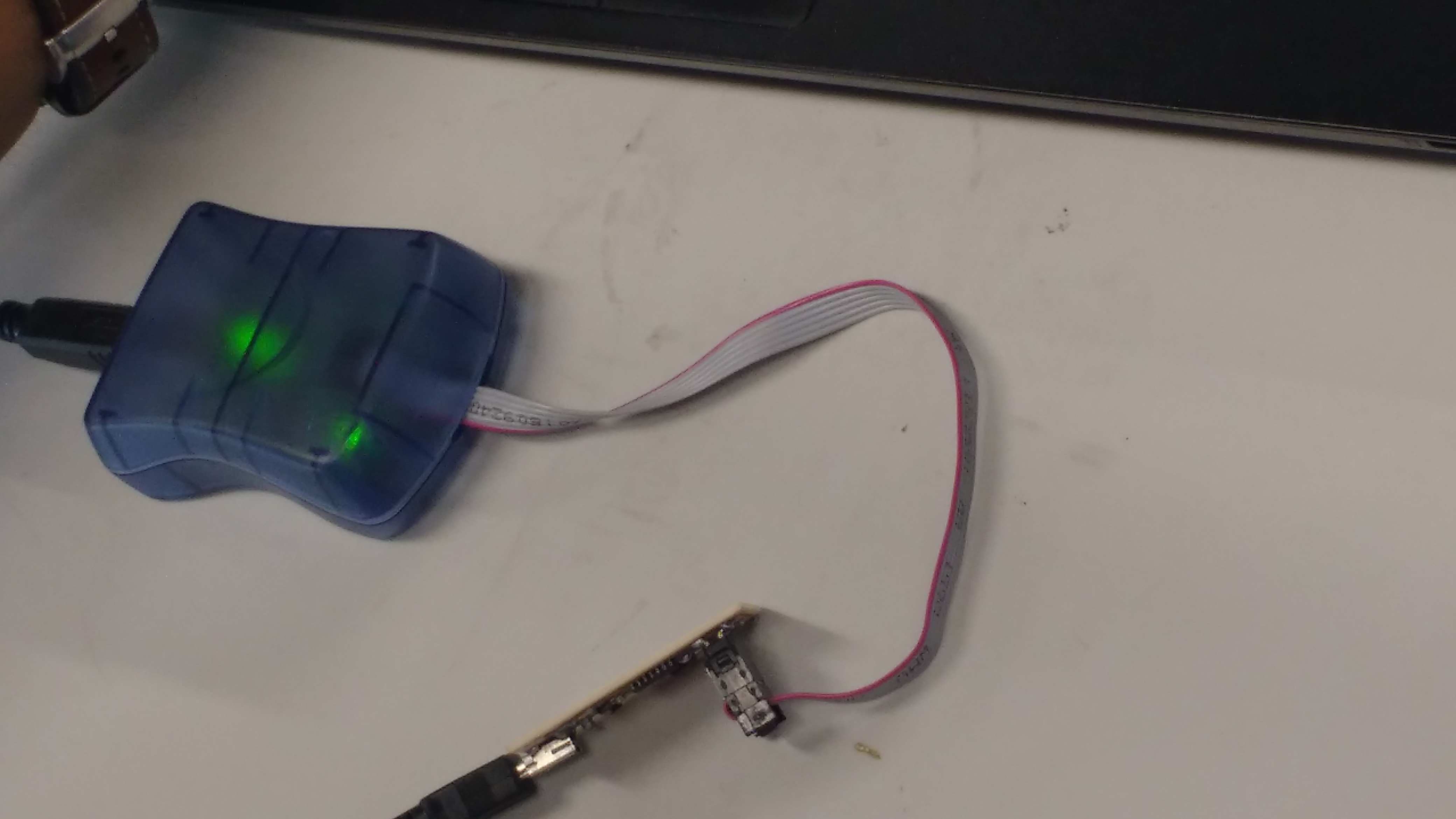
The Fab ISP that i choice is the David Mellis model, that looks like the picture below.
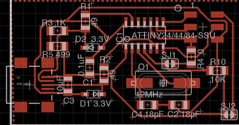
To have a second alternative of a ISP, I milled and make the Ali version of this. All the preocess is the same including soldering and programing.
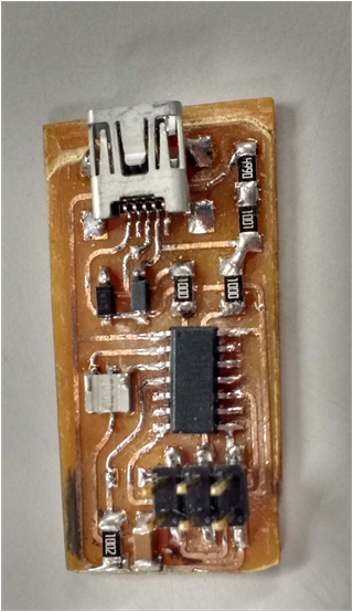
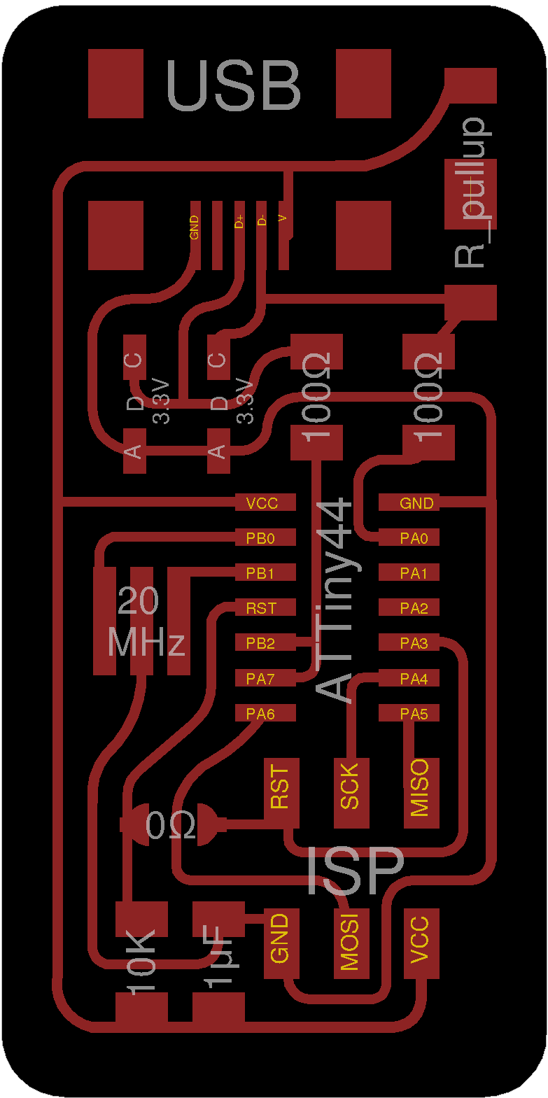
The new BIM to prepare this board is:
* 01 jack USB mini
* 02 1k ohm resistor
* 01 10k ohm resistor
* 01 499 ohm resistor
* 02 100 ohm resistor
* 02 3.3v zener diode
* 01 0.1uF condenser
* 01 0 ohm resistor
* 01 20 MHz crystal
* 01 2x3 jumper pinheader
* 01 AtTiny 44 microcontroller
* 01 jack USB mini
* 02 1k ohm resistor
* 01 10k ohm resistor
* 01 499 ohm resistor
* 02 100 ohm resistor
* 02 3.3v zener diode
* 01 0.1uF condenser
* 01 0 ohm resistor
* 01 20 MHz crystal
* 01 2x3 jumper pinheader
* 01 AtTiny 44 microcontroller
The process to generate the g code to mill the board, is documented here, in the week6.