


week 16
Interface & Application Programming.
Assignment:
Write an application that interfaces with an input &/or output device that you made, comparing as many tool options as possible.
Write an application that interfaces with an input &/or output device that you made, comparing as many tool options as possible.
Guillermo Jaramillo :: Fab Academy 2017
Fab Academy 2017

I take the Neil's Code in Python to interface the hello mic board, i modified the code to get another appearance an colors. So, the purpose of the program is read the serial data from the board that uses a Attniy45 micro controller and move a bar and display a number in order to the data readed.
I must modify the code because the original python code has a difference with the library tkinter, that has two different names, so to fix this, i modified the code to run both versions.
Here the python code.
try:
# for Python2
from Tkinter import *
except ImportError:
# for Python3
from tkinter import *
import serial
WINDOW = 300 # window size
eps = 0.75 # filter fraction
filt = 0.0 # filtered value
def idle(parent,canvas):
global filt, eps
#
# idle routine
#
byte2 = 0
byte3 = 0
byte4 = 0
ser.flush()
#
# find framing
The second tool that I try is with processing. Based on a free sample code by Ira Greenberg I make a adaptation to open a serial port and read data from it. This program makes a non-orthogonal reflection, based on the equation (R = 2N(N*L)-L) where R is the reflection vector, N is the normal, and L is the incident vector. Here is the code:
import processing.serial.*;
int inByte = 0;
// The serial port:
Serial myPort;
// Position of left hand side of floor
PVector base1;
// Position of right hand side of floor
PVector base2;
// Length of floor
float baseLength;
// An array of subpoints along the floor path
PVector[] coords;
// Variables related to moving ball
PVector position;
PVector velocity;
float r = 6;
float speed = 3.5;
void setup() {
// List all the available serial ports
printArray(Serial.list());
// Open the port you are using at the rate you want:
myPort = new Serial(this, Serial.list()[32], 9600);
size(640, 360);
fill(0,0,0);
base1 = new PVector(0, height-150);
base2 = new PVector(width, height);
createGround();
// start ellipse at middle top of screen
position = new PVector(width/2, 0);
// calculate initial random velocity
velocity = PVector.random2D();
velocity.mult(speed);
}
void draw() {
while (myPort.available() > 0) {
//inByte = myPort.read();
//inByte = myPort.readChar();
//myPort.clear();
for (int i = 0; i < 1; i = i+1) {
inByte = myPort.read();}
// if (inByte = 0) { inByte = random(255)*1;}
println(inByte);
}
// draw background
fill(0, 12);
noStroke();
rect(0, 0, width, height);
// draw base
fill(0,255,255);
quad(base1.x, base1.y, base2.x, base2.y, base2.x, height, 0, height);
// calculate base top normal
PVector baseDelta = PVector.sub(base2, base1);
baseDelta.normalize();
PVector normal = new PVector(-baseDelta.y, baseDelta.x);
// draw ellipse
noStroke();
fill(inByte*random(50),inByte*random(50),inByte*random(50));
ellipse(position.x, position.y, r*2, r*2);
// move elipse
position.add(velocity);
// normalized incidence vector
PVector incidence = PVector.mult(velocity, -1);
incidence.normalize();
// detect and handle collision
for (int i=0; i<coords.length; i++) {
// check distance between ellipse and base top coordinates
if (PVector.dist(position, coords[i]) < r) {
// calculate dot product of incident vector and base top normal
float dot = incidence.dot(normal);
// calculate reflection vector
// assign reflection vector to direction vector
velocity.set(2*normal.x*dot - incidence.x, 2*normal.y*dot - incidence.y, 0);
velocity.mult(speed);
// draw base top normal at collision point
stroke(255, 128, 0);
line(position.x, position.y, position.x-normal.x*100, position.y-normal.y*100);
}
}
// detect boundary collision
// right
if (position.x > width-r) {
position.x = width-r;
velocity.x *= -1;
}
// left
if (position.x < r) {
position.x = r;
velocity.x *= -1;
}
// top
if (position.y < r) {
position.y = r;
velocity.y *= -1;
// randomize base top
base1.y = random(height-100, height);
base2.y = random(height-100, height);
createGround();
}
}
// Calculate variables for the ground
void createGround() {
// calculate length of base top
baseLength = PVector.dist(base1, base2);
// fill base top coordinate array
coords = new PVector[ceil(baseLength)];
for (int i=0; i<coords.length; i++) {
coords[i] = new PVector();
coords[i].x = base1.x + ((base2.x-base1.x)/baseLength)*i;
coords[i].y = base1.y + ((base2.y-base1.y)/baseLength)*i;
}
}
And to see the final result is execute the code in terminal window with an order like this:
nemo@NEMOSTATION:~/Downloads/processing-3.3.3$ sudo ./processing ./prg1/prg1.pde
#
while 1:
byte1 = byte2
byte2 = byte3
byte3 = byte4
byte4 = ord(ser.read())
if ((byte1 == 1) & (byte2 == 2) & (byte3 == 3) & (byte4 == 4)):
break
#
# read and plot
#
up_low = ord(ser.read())*10
up_high = ord(ser.read())*10
down_low = ord(ser.read())*10
down_high = ord(ser.read())*10
up_value = 256*up_high + up_low
down_value = 256*down_high + down_low
value = (up_value - down_value)
filt = (1-eps)*filt + eps*value
x = int(.2*WINDOW + (.9-.2)*WINDOW*filt/10000.0)
canvas.itemconfigure("text",text="%.1f"%filt)
canvas.coords('rect1',.2*WINDOW,.05*WINDOW,x,.2*WINDOW)
canvas.coords('rect2',x,.05*WINDOW,.9*WINDOW,.2*WINDOW)
canvas.update()
parent.after_idle(idle,parent,canvas)
port = '/dev/ttyUSB0'
#
# open serial port
#
ser = serial.Serial(port,9600)
ser.setDTR()
#
# set up GUI
#
root = Tk()
root.title('Probe.serial.py :: Fab UTEC (e to exit)')
root.bind('e','exit')
canvas = Canvas(root, width=WINDOW, height=.5*WINDOW, background='grey')
#
canvas.create_text(.1*WINDOW,.125*WINDOW,text="1",font=("Helvetica", 24),tags="text",fill="#0000b0")
canvas.create_rectangle(.3*WINDOW,.2*WINDOW,.2*WINDOW,.05*WINDOW, tags='rect1', fill='#00ff00')
canvas.create_rectangle(.9*WINDOW,.2*WINDOW,.3*WINDOW,.05*WINDOW, tags='rect2', fill='#0000b0')
canvas.pack()
#
# start idle loop
#
root.after(100,idle,root,canvas)
root.mainloop()
The next step is execute the code in a terminal window:
nemo@NEMOSTATION:~/Downloads/Hello45$ sudo python3 Probe.serial.py
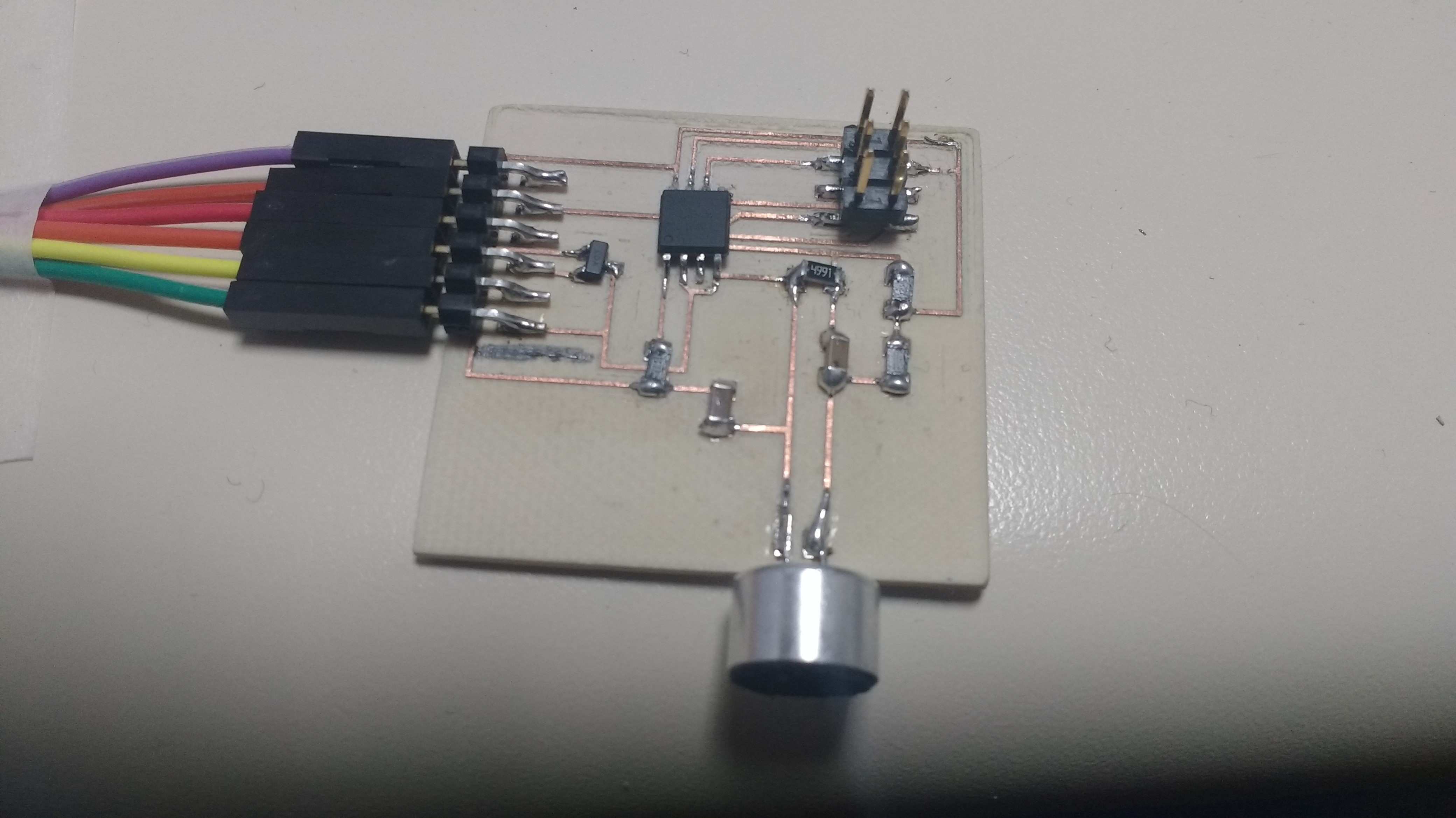
This is the Hello Mic 45 board
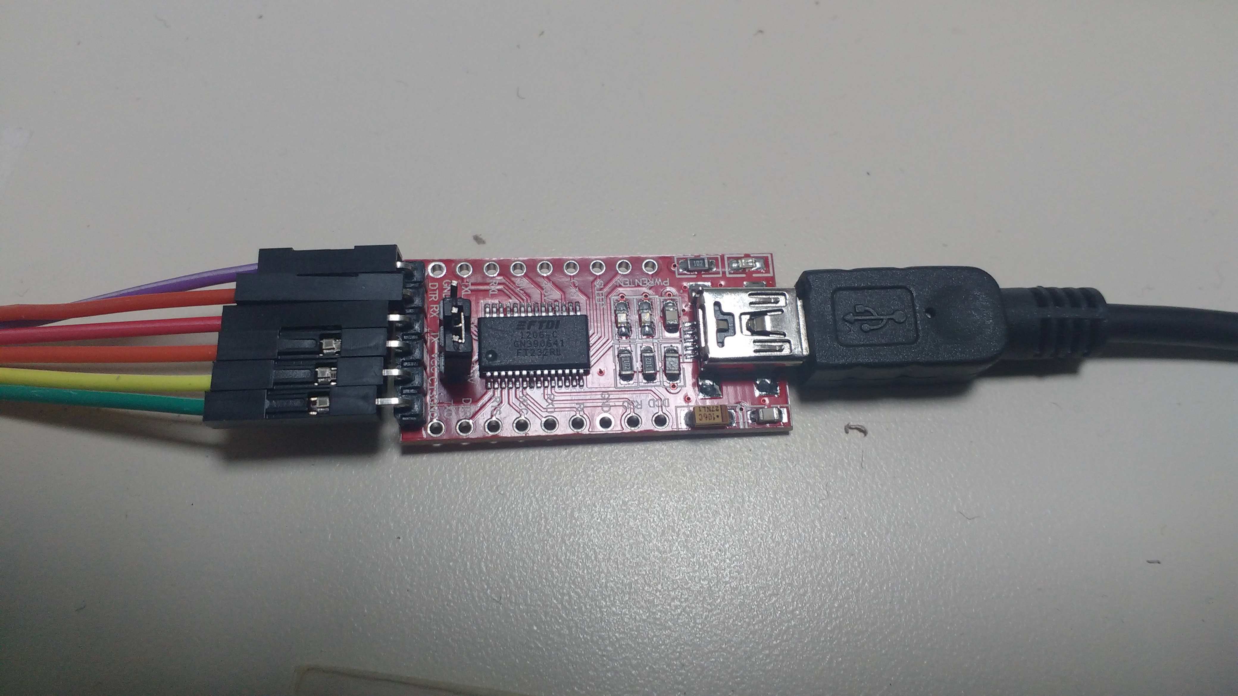
This is the FTDI RS232 board to communicate via serial port.
So when the data in the serial port changes, the color of the bouncing ball in screen changes over colors. The data that was reading is visible too as numbers in the bottom side of the IDE of processing, because i insert a code line to print this such as a control mechanism.
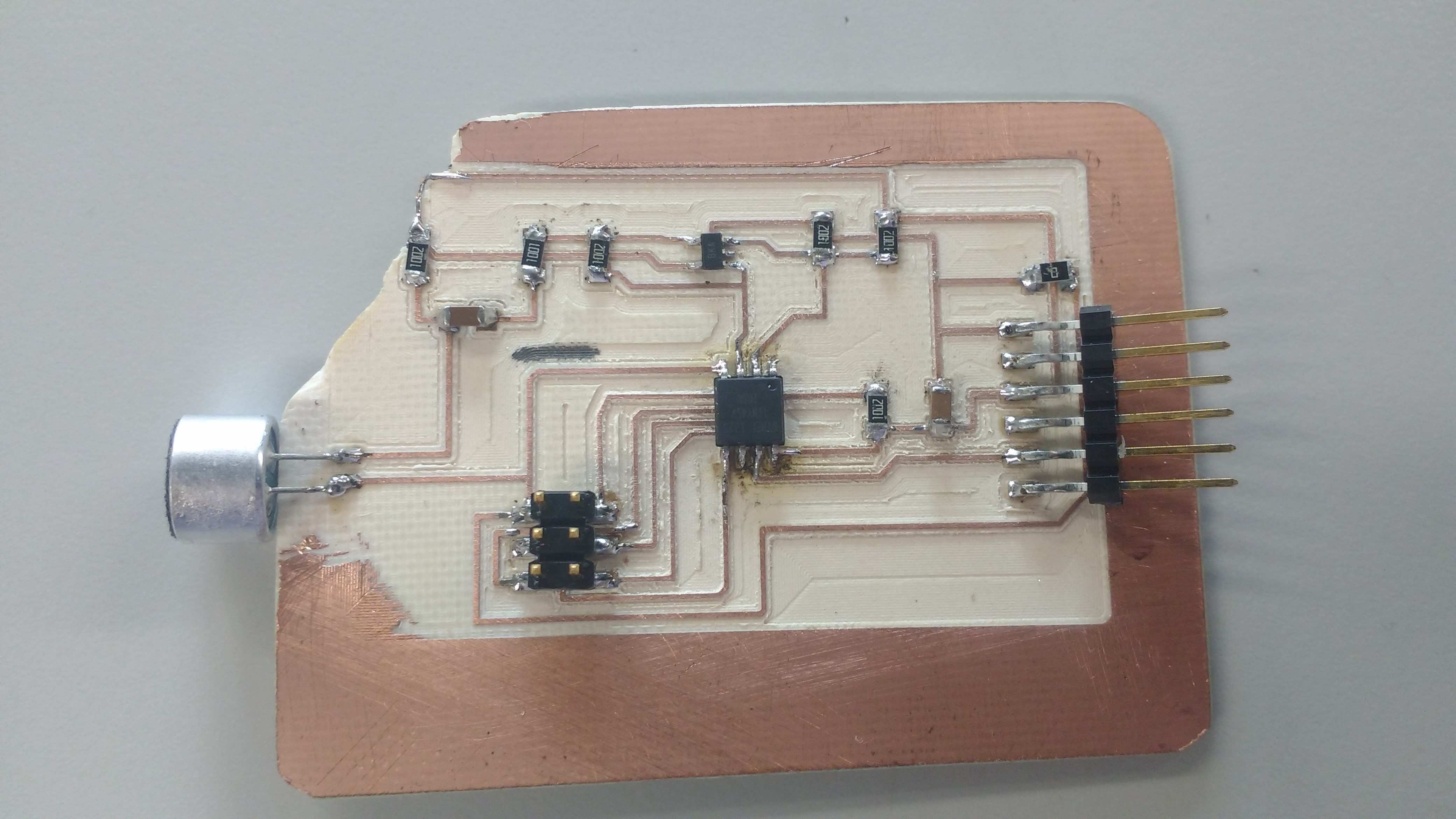
Here is my own version of the input microphone adding a opamp to amplify the signal and get best results.