week 15
Networking & Communications.
Assignment:
Design and build a wired &/or wireless network connecting at least two processor.
Design and build a wired &/or wireless network connecting at least two processor.
Guillermo Jaramillo :: Fab Academy 2017
Fab Academy 2017

Ok, now I start with the Neil's Attiny45 board serial communication board. In talk with my Instructor and he tell me that its necessary to redisign the board and plain ho to communicate them.
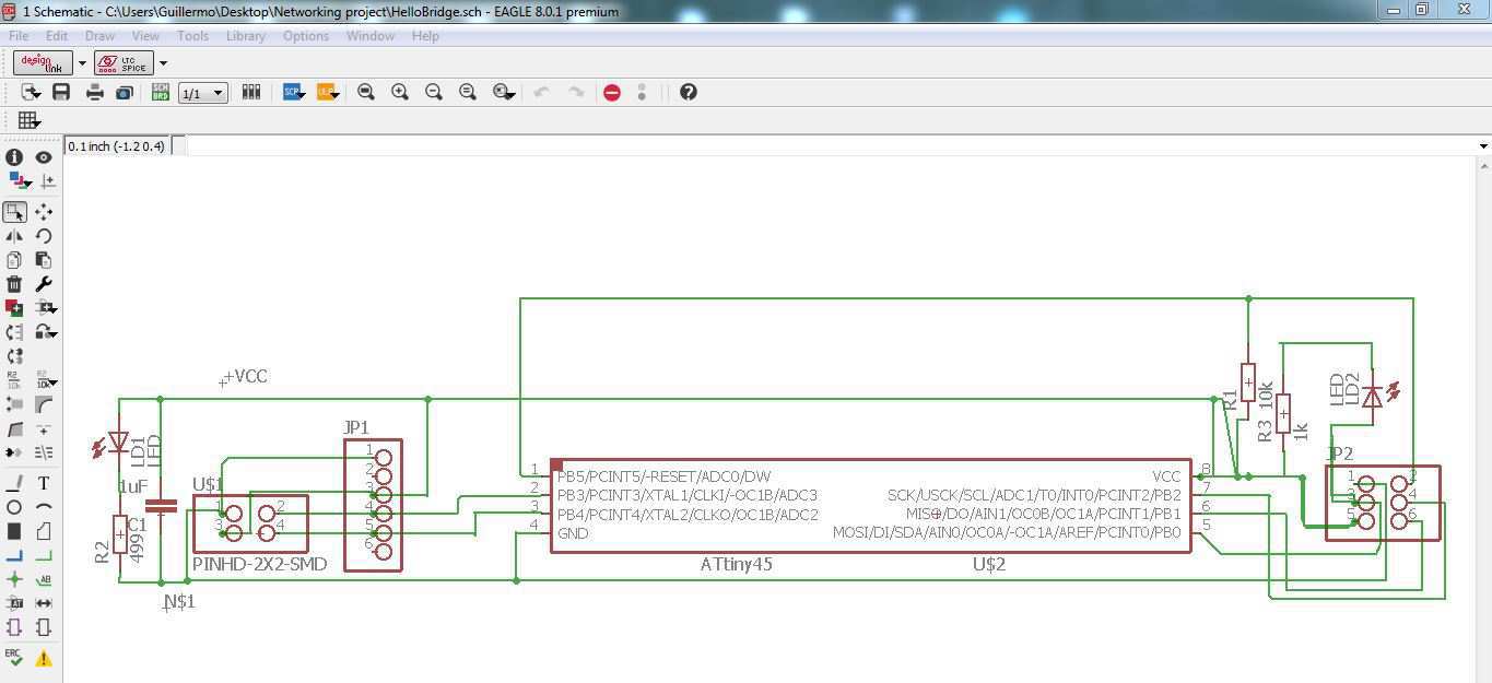
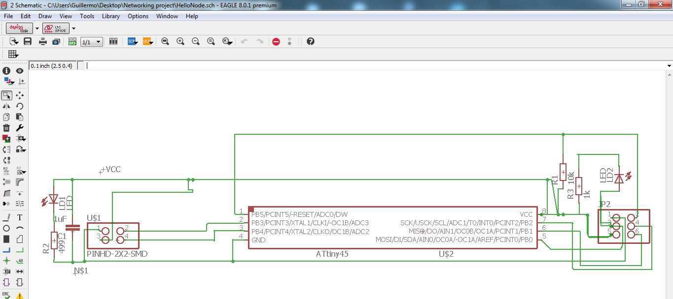
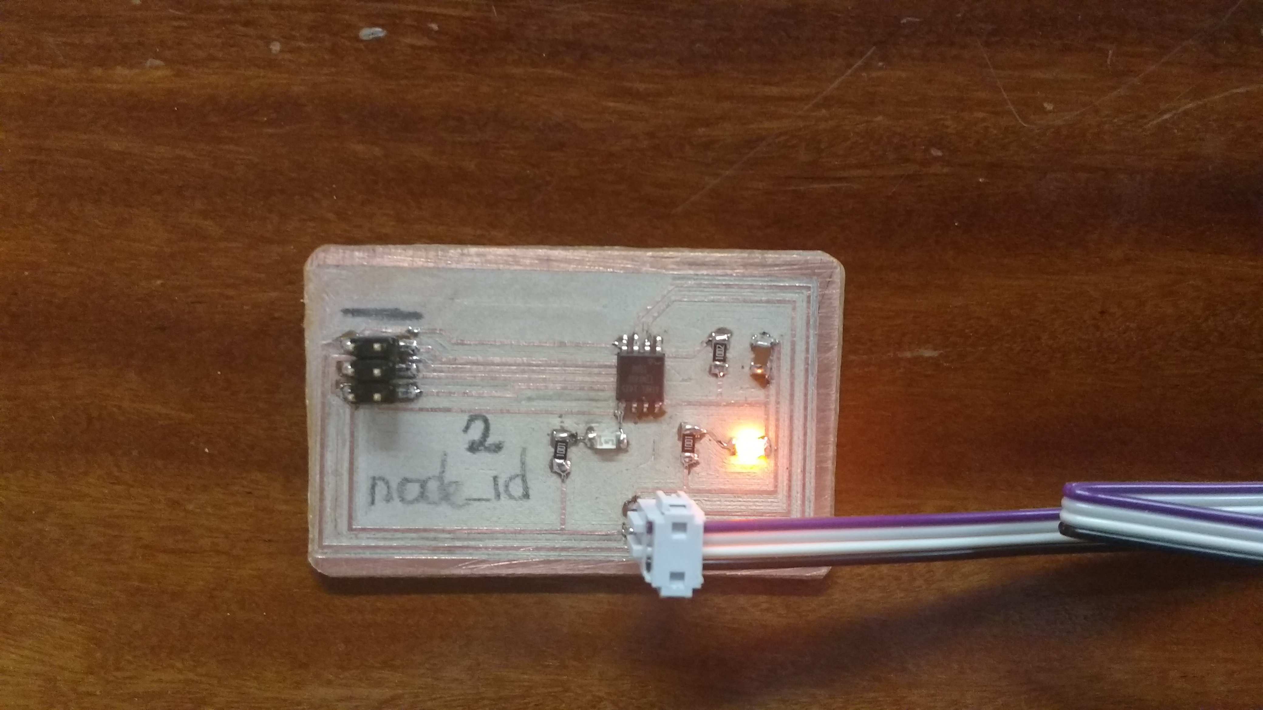
So, here is my versión of the Neil's Attiny45 board, including a led for indicate power supply.
So, here is my versión of the Neil's Attiny45 board, including a led for indicate power supply.
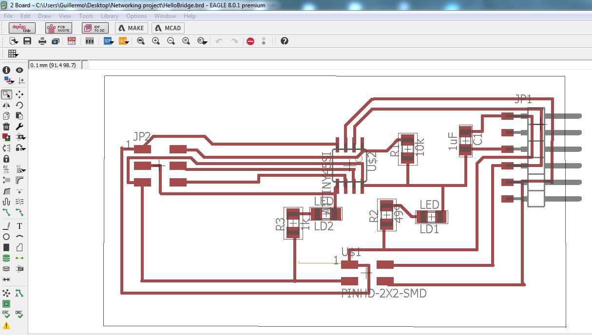
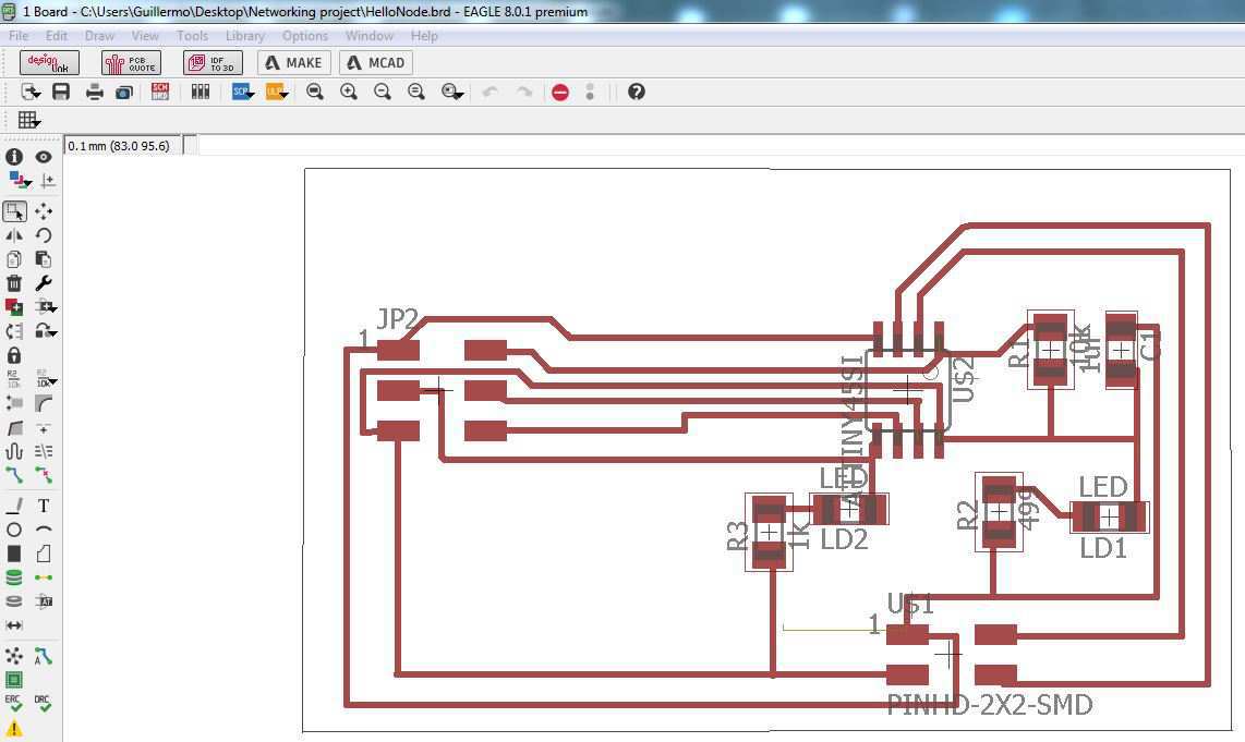
And here the board design.
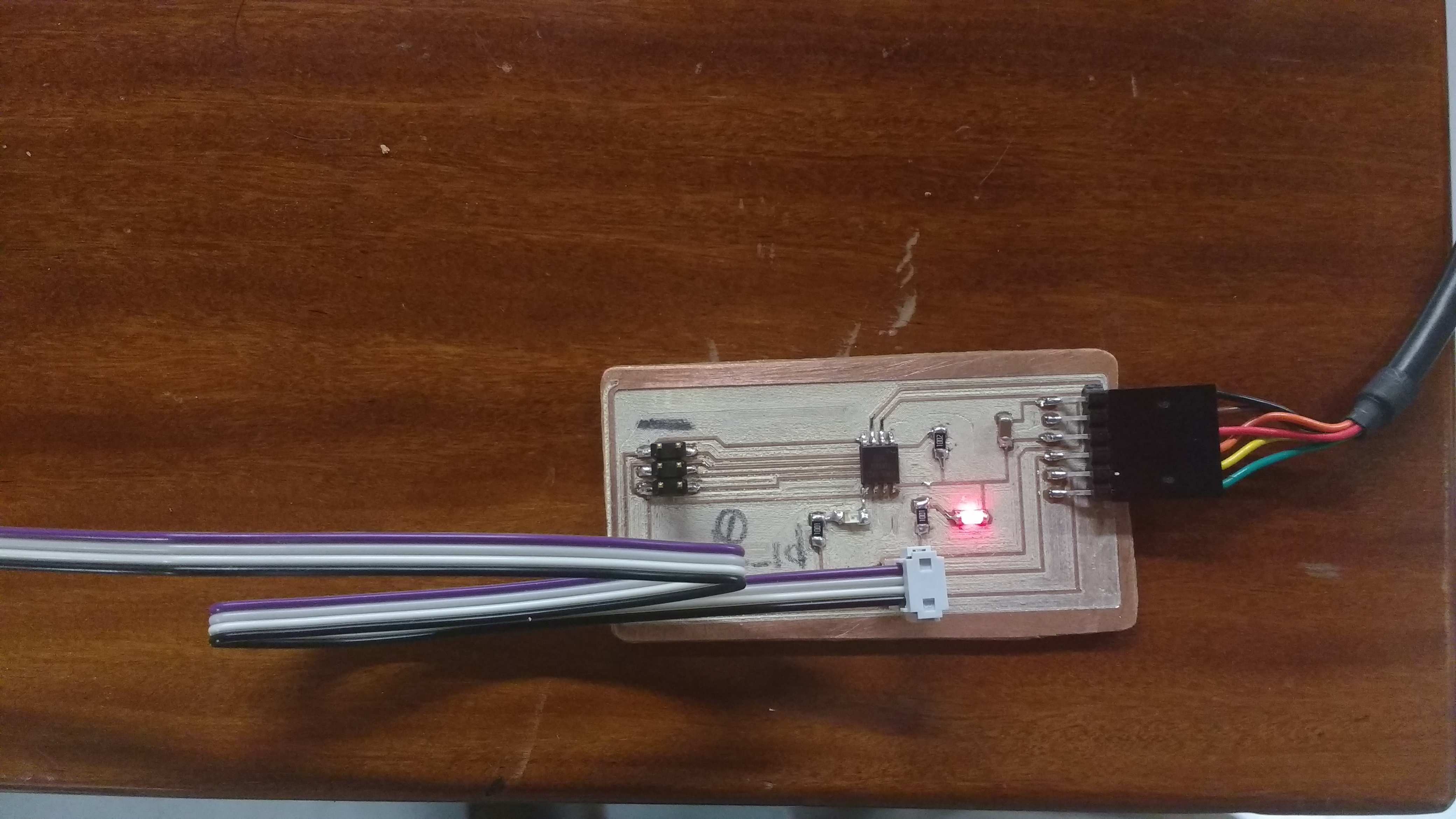
The same process is made with the other card. Last one is called bridge node, because is the final part of the network, and includes one jumper pin (1x6) where connects TFDI cable to communicate the network with the PC. The second card is called just node, and i will make a couple of this. Here the design.
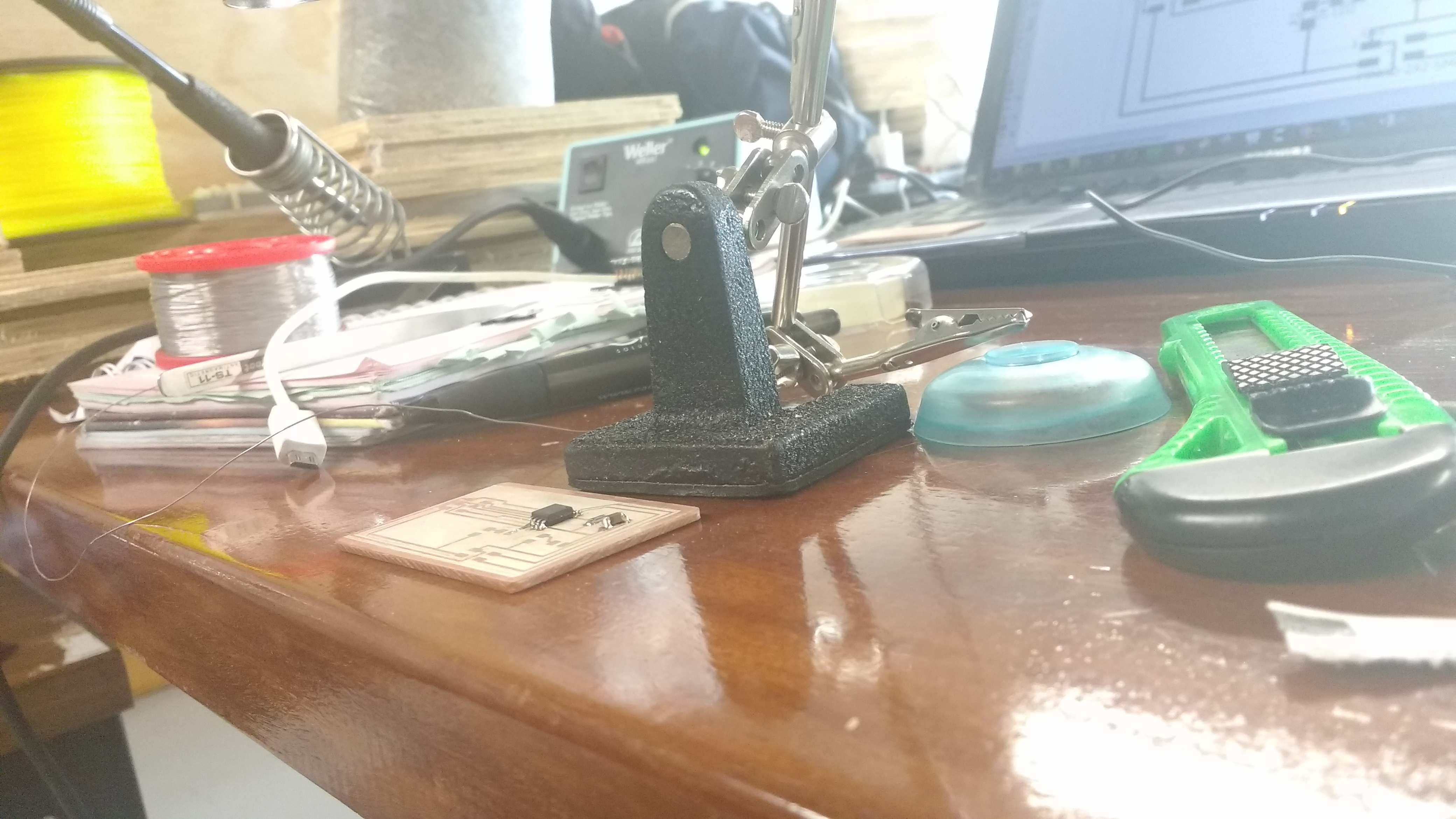
So the next step is make the boards milling it. And the next step is solder the components. In a part of laboratory called: "Jaramillo Ecosystem"
Now when the board are ready, its time to program them. To do this i must change the line:
#define node_id '0'
Because there are three nodes such are: 0, 1 and 2. So I need three version of the code, each with the right number of the node. Finally its necessary program each board with a unique code in three versions.
nemo@NEMOSTATION:~/Downloads/node.bridge$ sudo make -f hello.bus.45.make program-usbtiny
[sudo] password for nemo:
avr-objcopy -O ihex hello.bus.45.out hello.bus.45.c.hex;\
avr-size --mcu=attiny45 --format=avr hello.bus.45.out
AVR Memory Usage
----------------
Device: attiny45
Program: 766 bytes (18.7% Full)
(.text + .data + .bootloader)
Data: 4 bytes (1.6% Full)
(.data + .bss + .noinit)
avrdude -p t45 -P usb -c usbtiny -U flash:w:hello.bus.45.c.hex
avrdude: AVR device initialized and ready to accept instructions
Reading | ################################################## | 100% 0.00s
avrdude: Device signature = 0x1e9206 (probably t45)
avrdude: NOTE: "flash" memory has been specified, an erase cycle will be performed
To disable this feature, specify the -D option.
avrdude: erasing chip
avrdude: reading input file "hello.bus.45.c.hex"
avrdude: input file hello.bus.45.c.hex auto detected as Intel Hex
avrdude: writing flash (766 bytes):
Writing | ################################################## | 100% 0.74s
avrdude: 766 bytes of flash written
avrdude: verifying flash memory against hello.bus.45.c.hex:
avrdude: load data flash data from input file hello.bus.45.c.hex:
avrdude: input file hello.bus.45.c.hex auto detected as Intel Hex
avrdude: input file hello.bus.45.c.hex contains 766 bytes
avrdude: reading on-chip flash data:
Reading | ################################################## | 100% 0.87s
avrdude: verifying ...
avrdude: 766 bytes of flash verified
avrdude: safemode: Fuses OK (E:FF, H:DF, L:62)
avrdude done. Thank you.
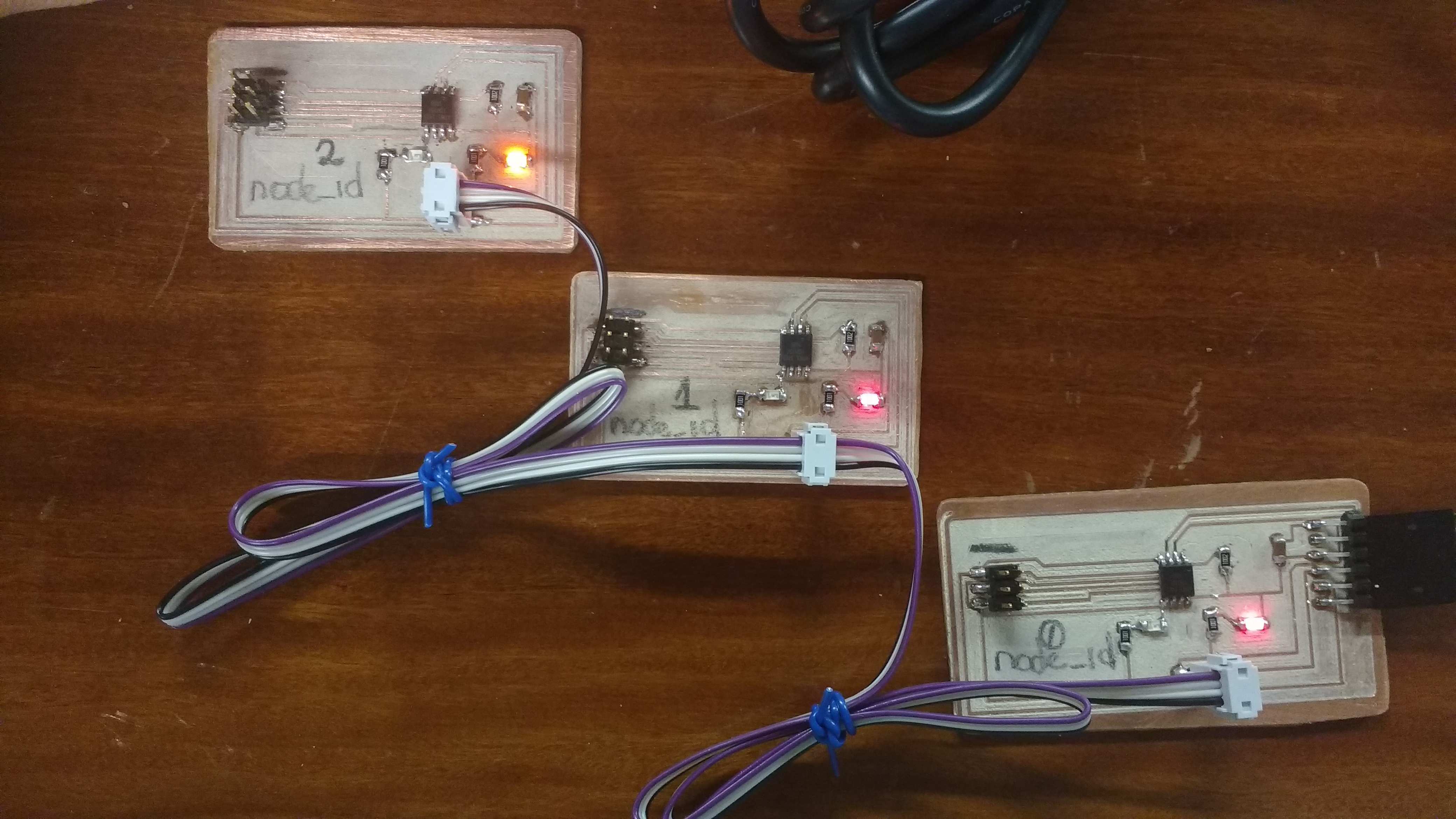
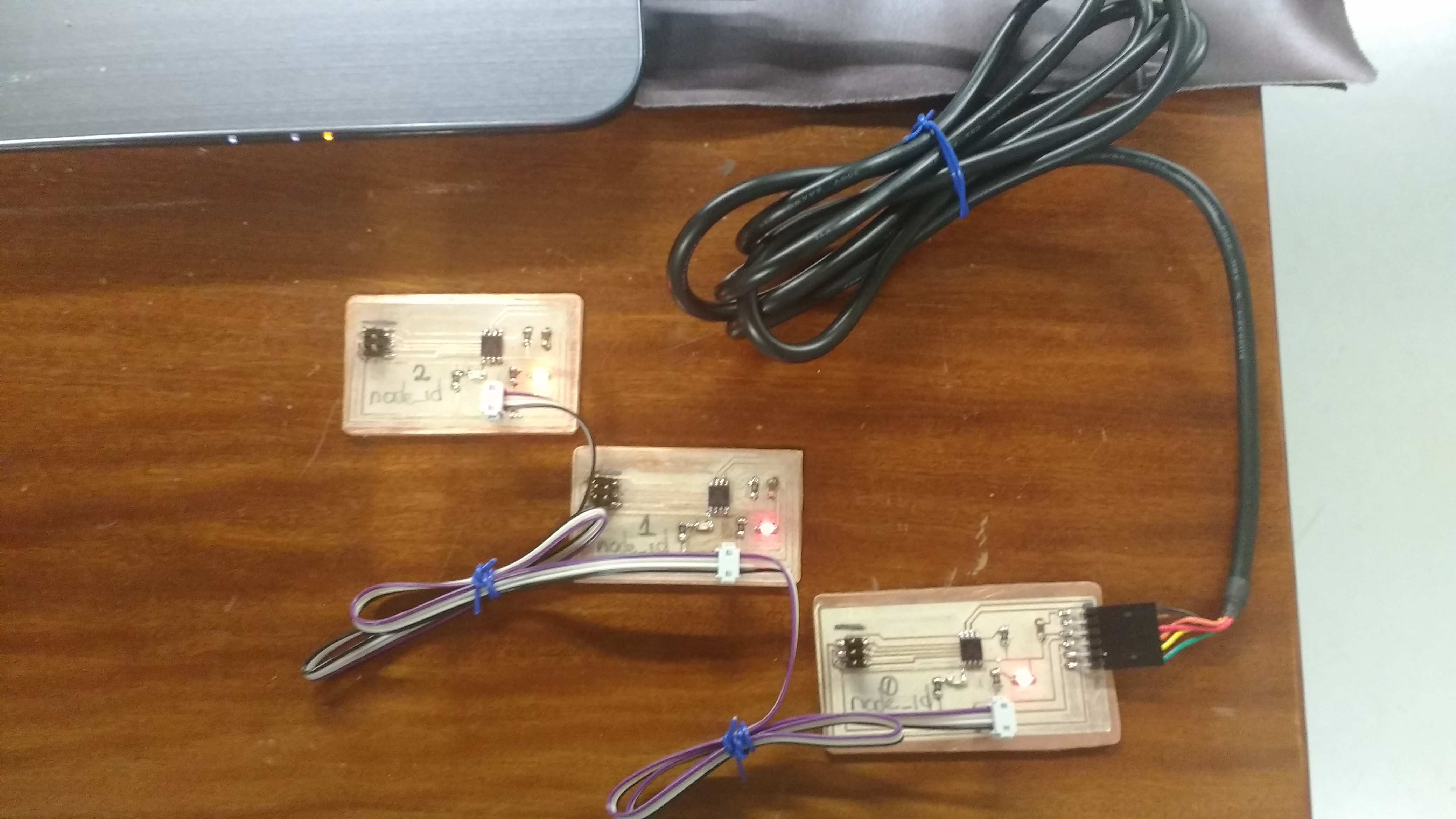
Now its time to to assemble the network, disconnect the ISP and connect the flat with 4 wires to create the physical layer of the network.
Three times . . . using my ISP programmer.
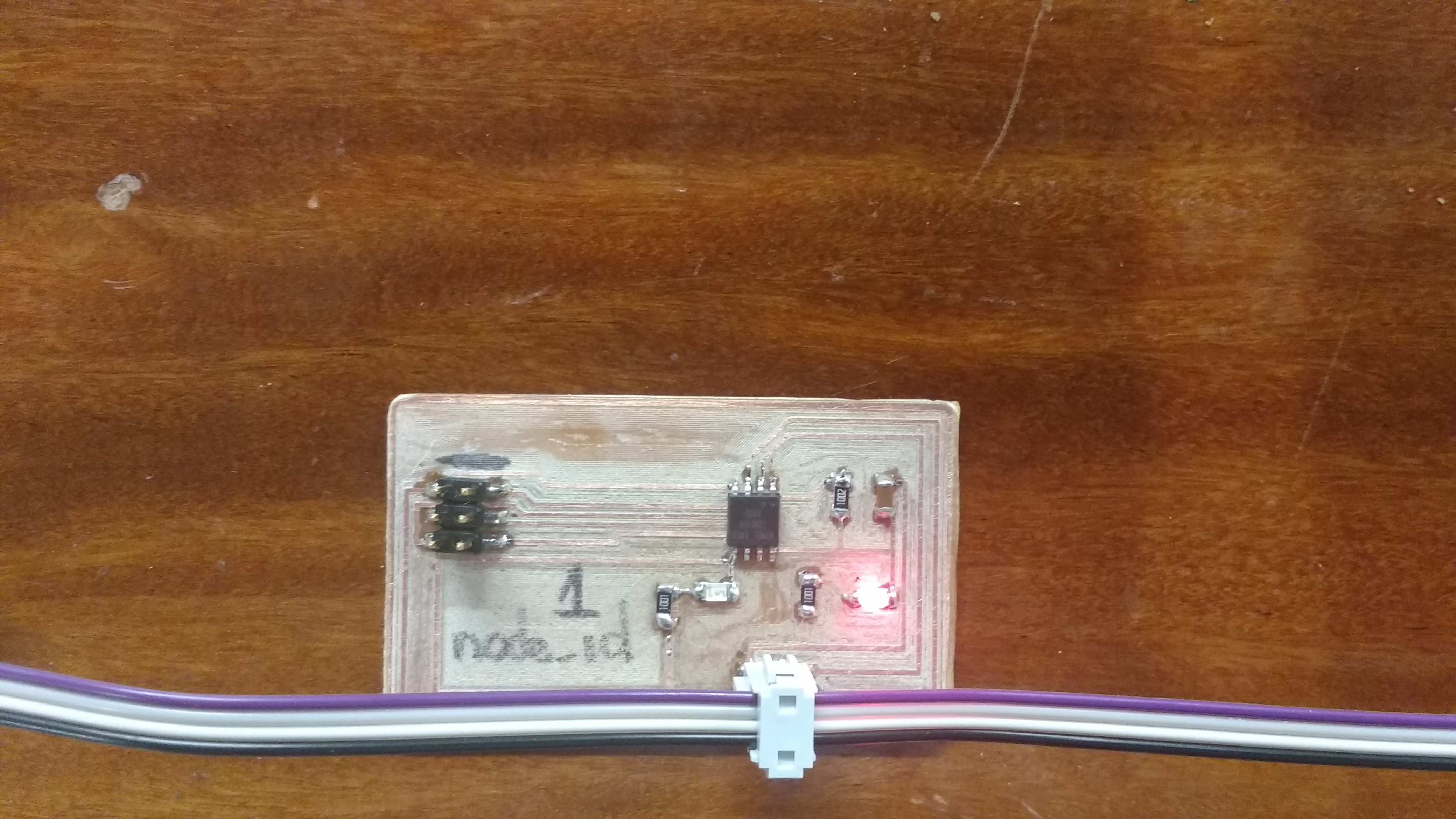
The network is ready and works properly.

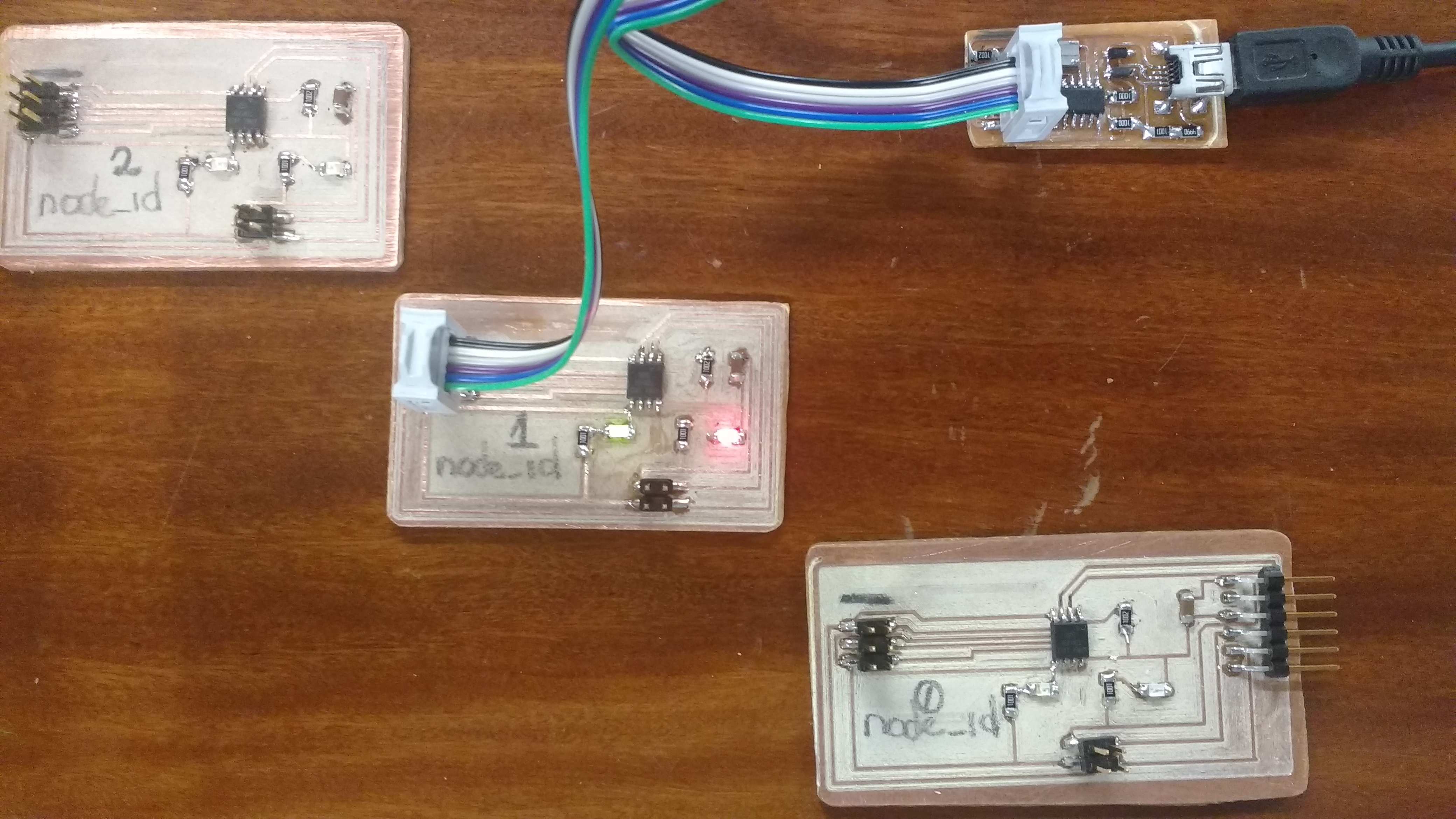

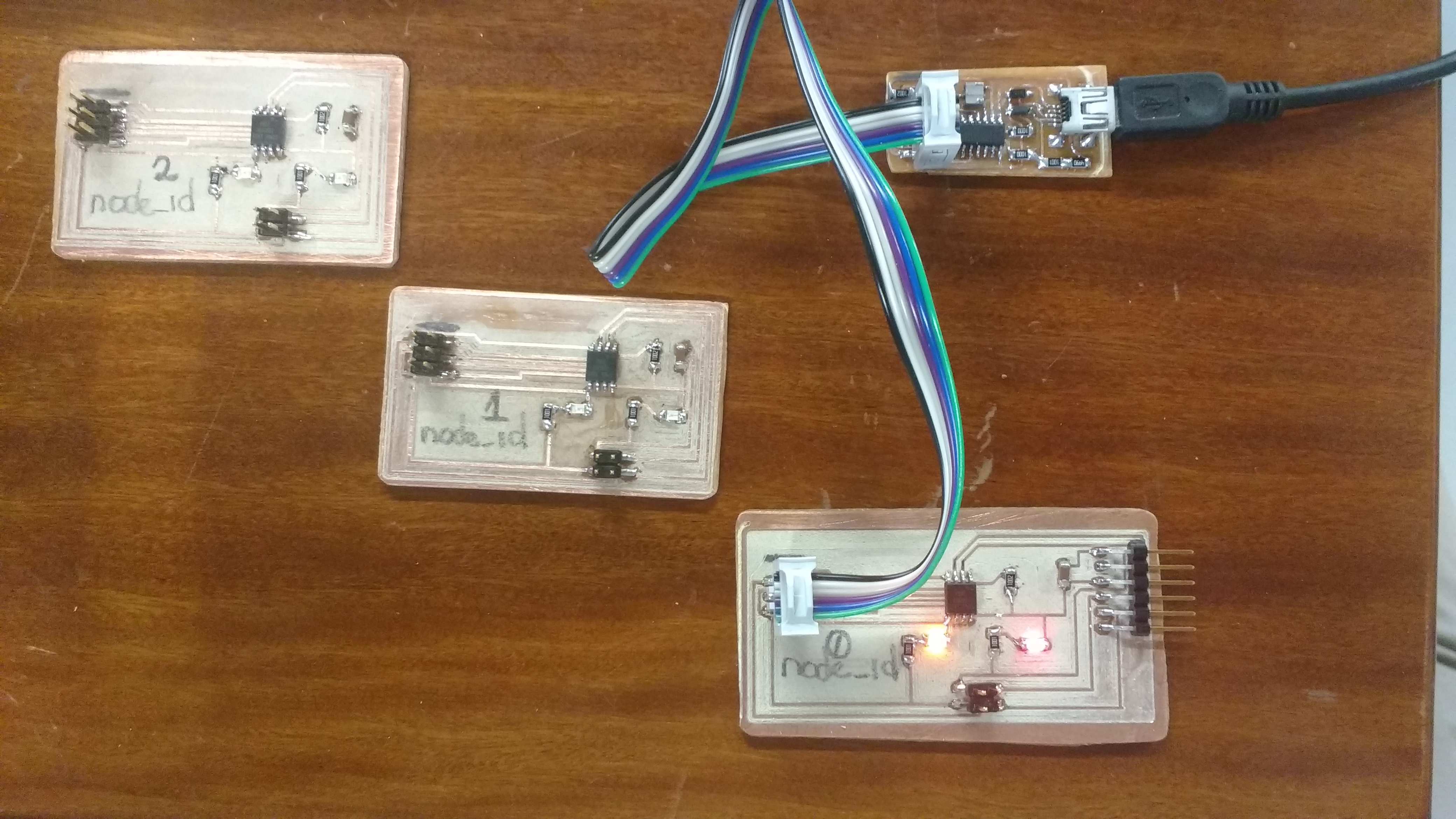
Node_id = 2
Node_id = 1
Node_id = 0
Next I connect the FTDI cable to communicate the network with the PC, now using Arduino on Windows. Finally I probe the connection with the serial monitor