


week 13
Input Devices.
Assignment:
Measure something: add a sensor to a microcontroller board that you have designed and read it.
Measure something: add a sensor to a microcontroller board that you have designed and read it.
Guillermo Jaramillo :: Fab Academy 2017
Fab Academy 2017

I started researching Niels' design for the Attiny45 and tested with an arduino one and an electret microphone.
When looking at the design I took into account that an external power supply is used with a 9V battery. Then I thought about modifying the design and powering the circuit from the FTDI.
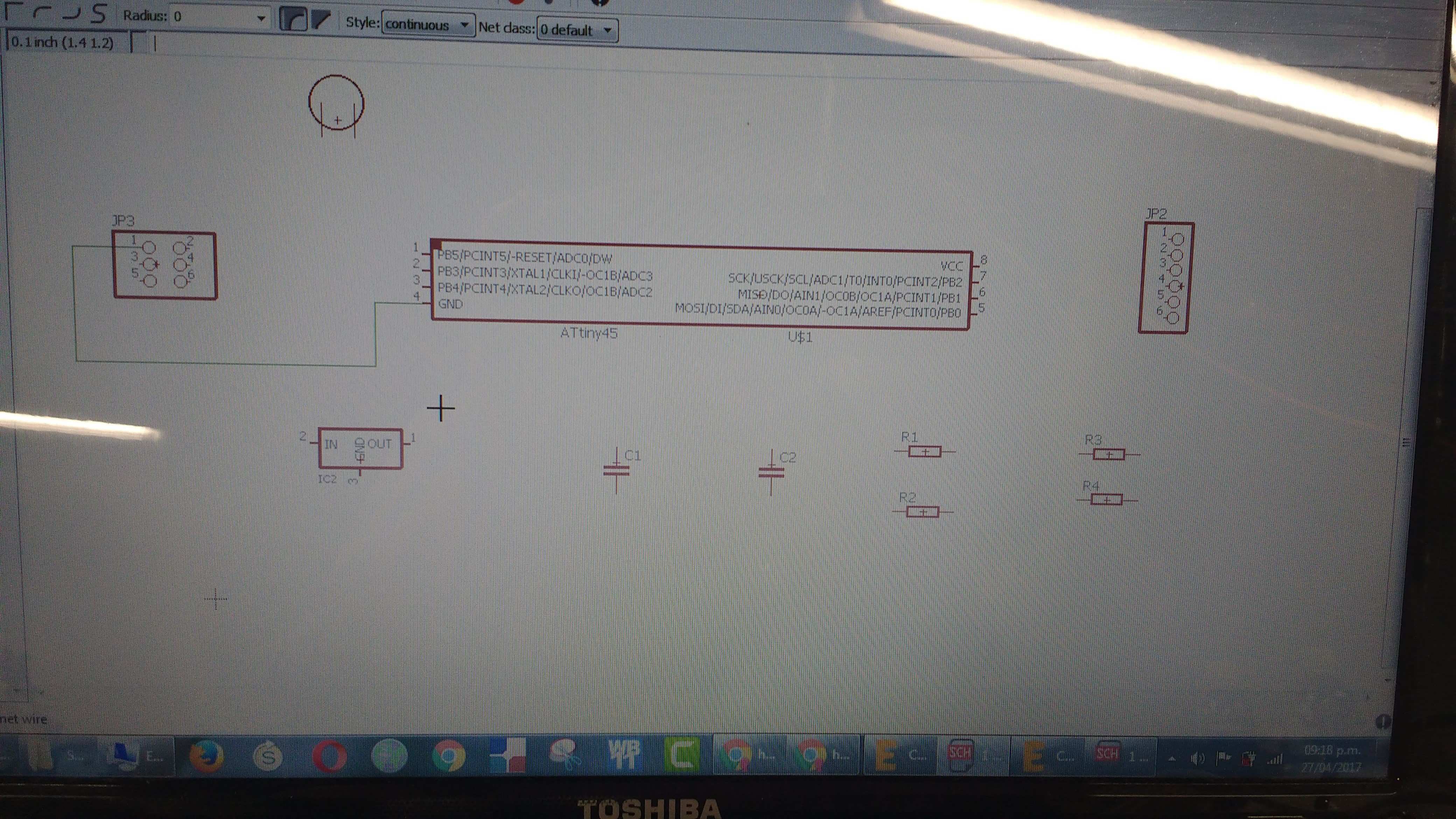
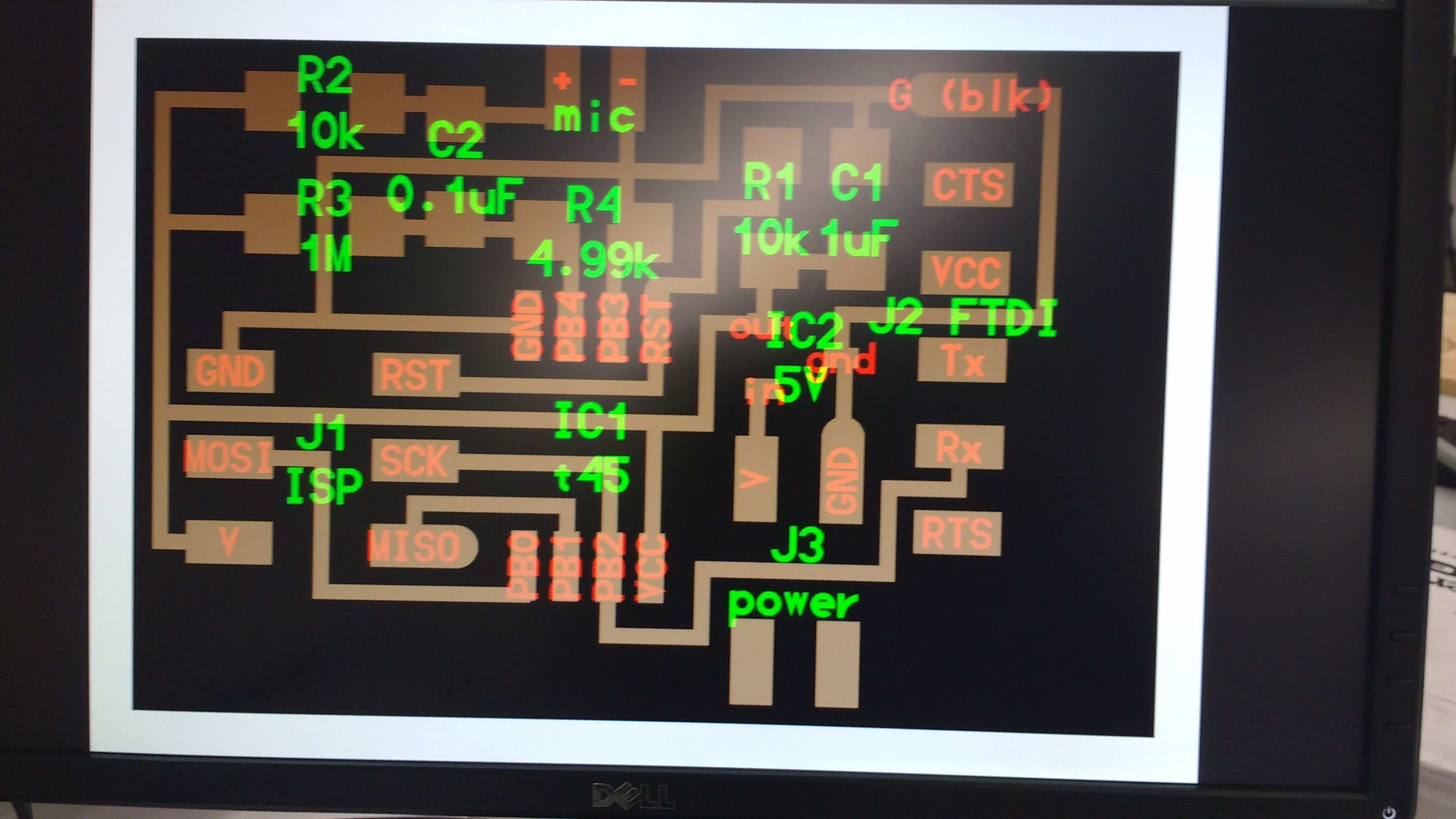
I used Eagle to completely redesign the Attiny45 board and make my own.
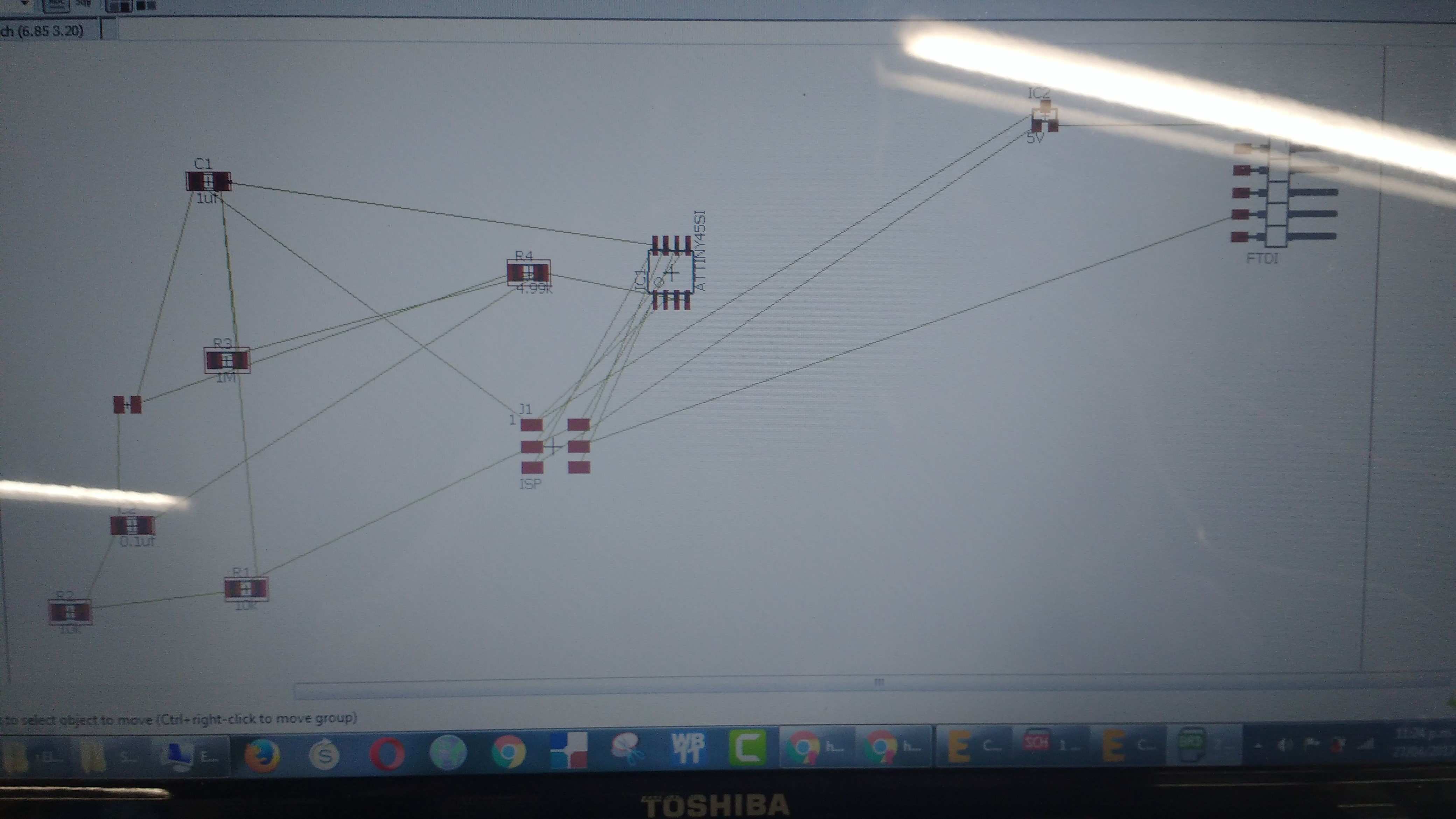
After much work I managed to rearrange the components to optimize the space.
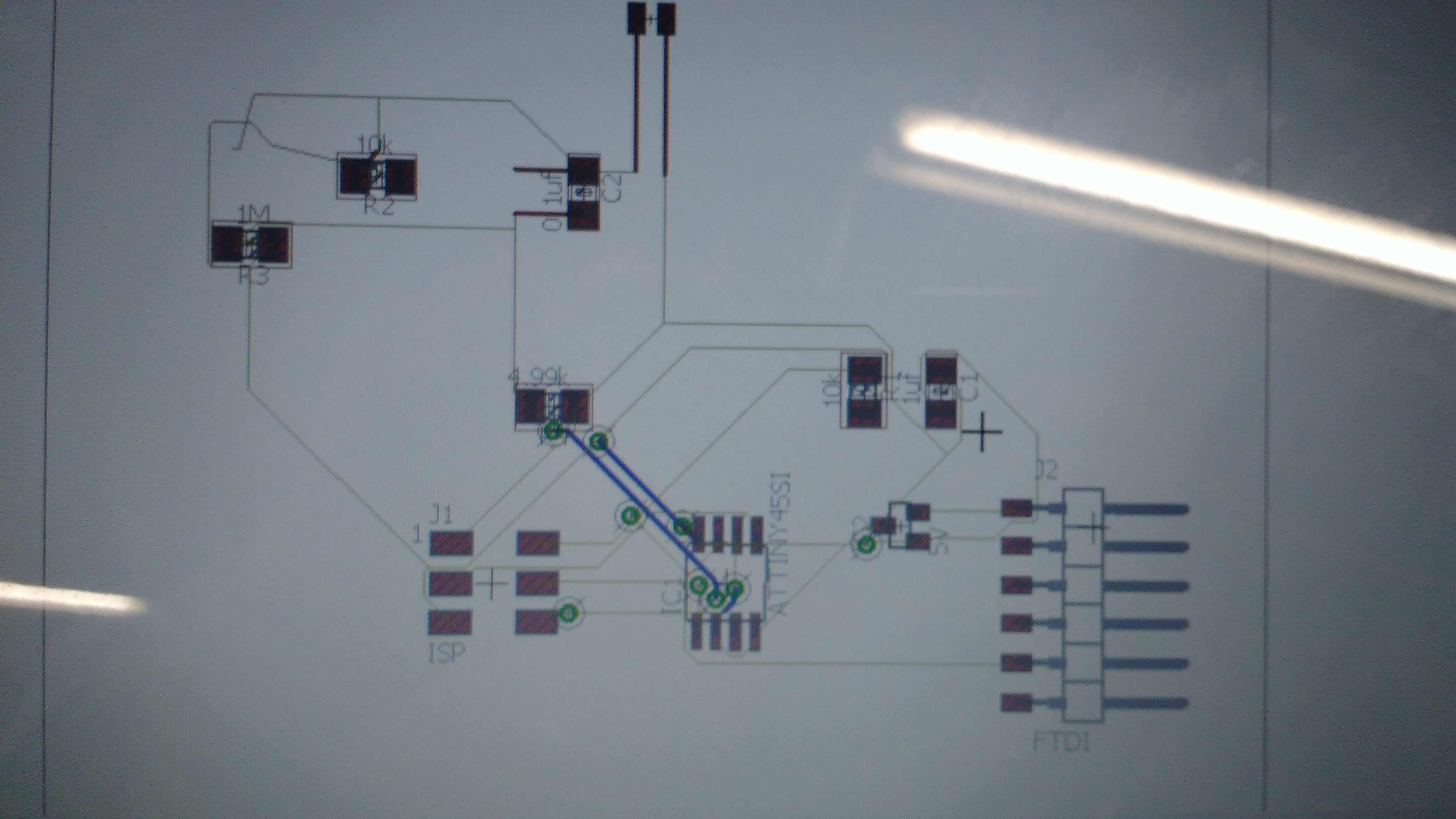
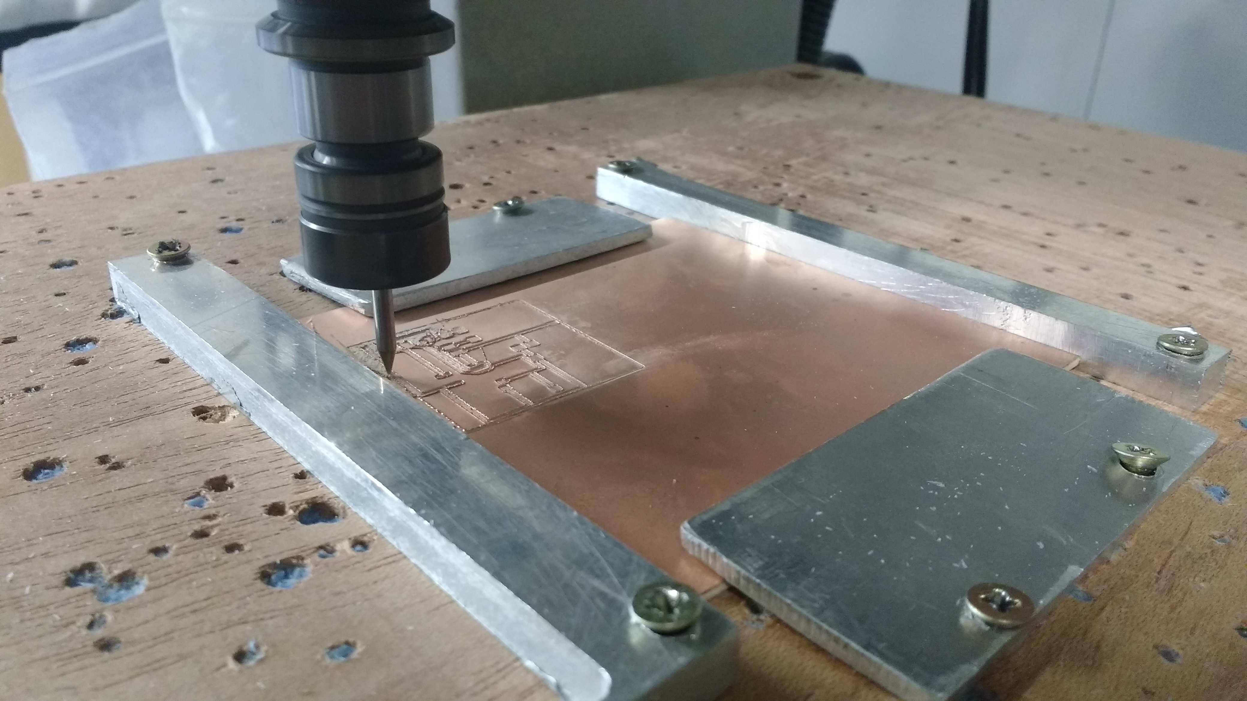
Once the board design was created I started to mill it in the Model 540.
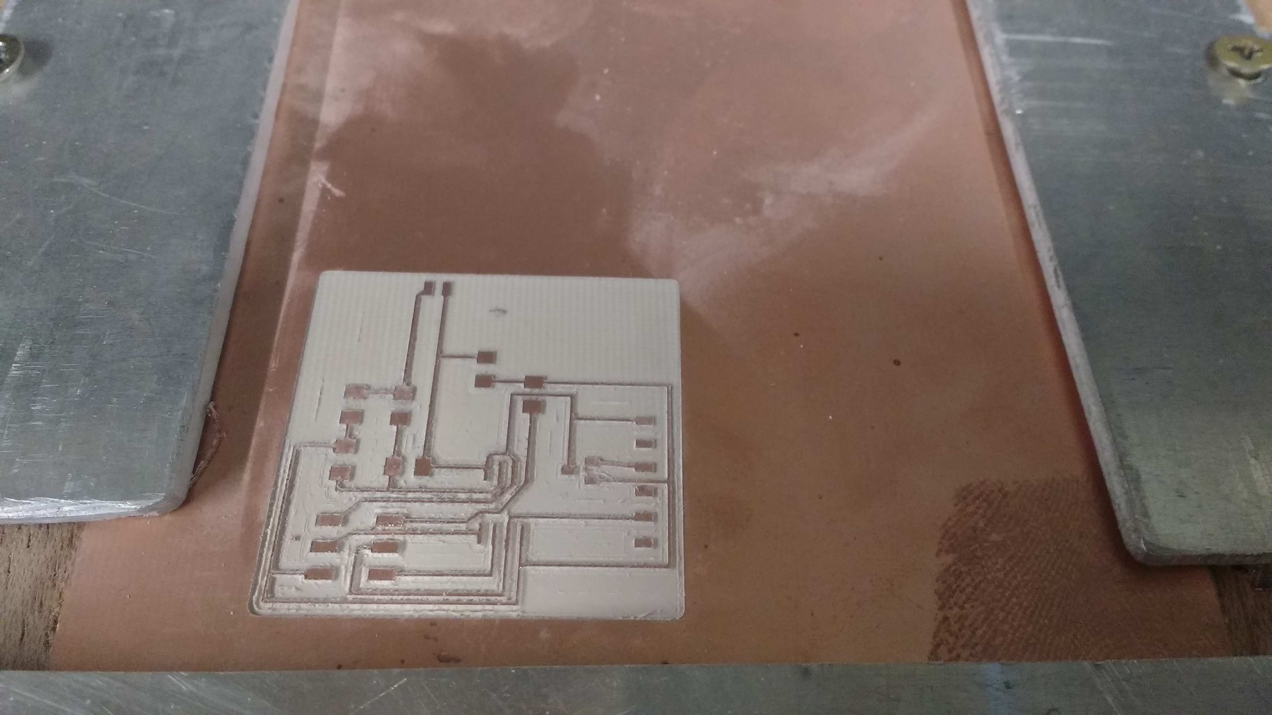
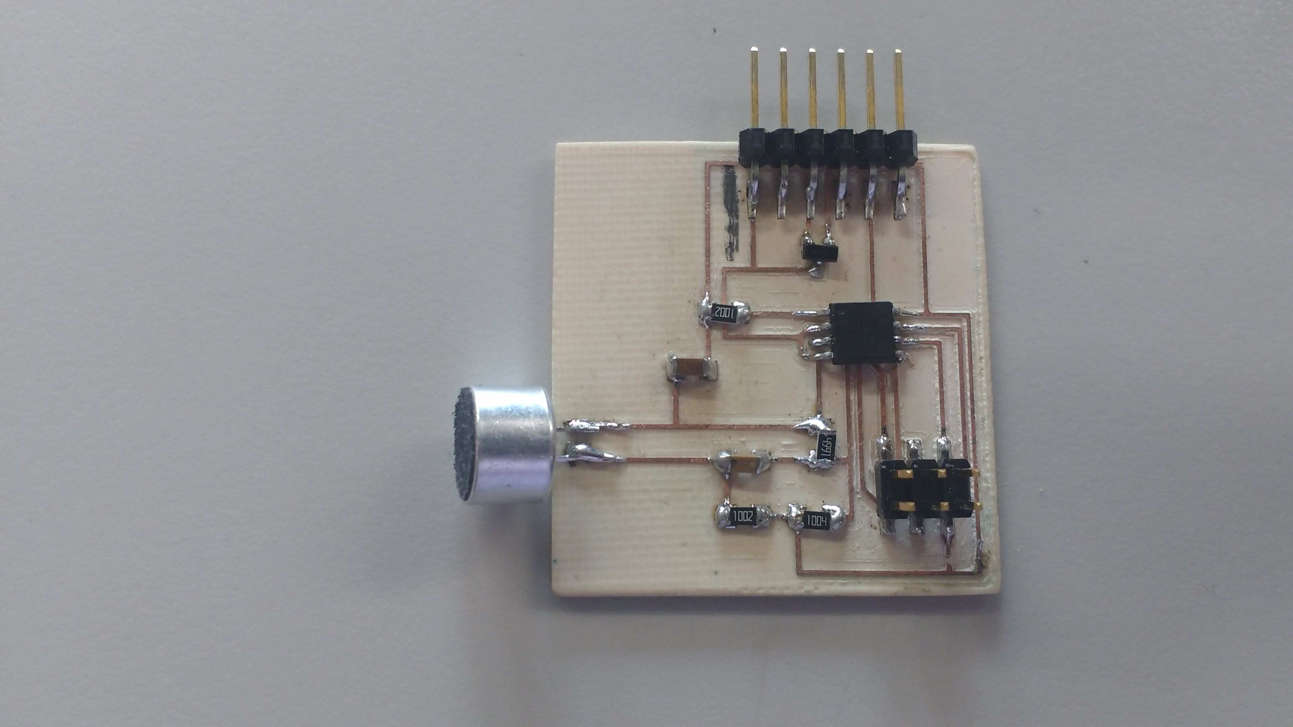
The board finally looks like this.
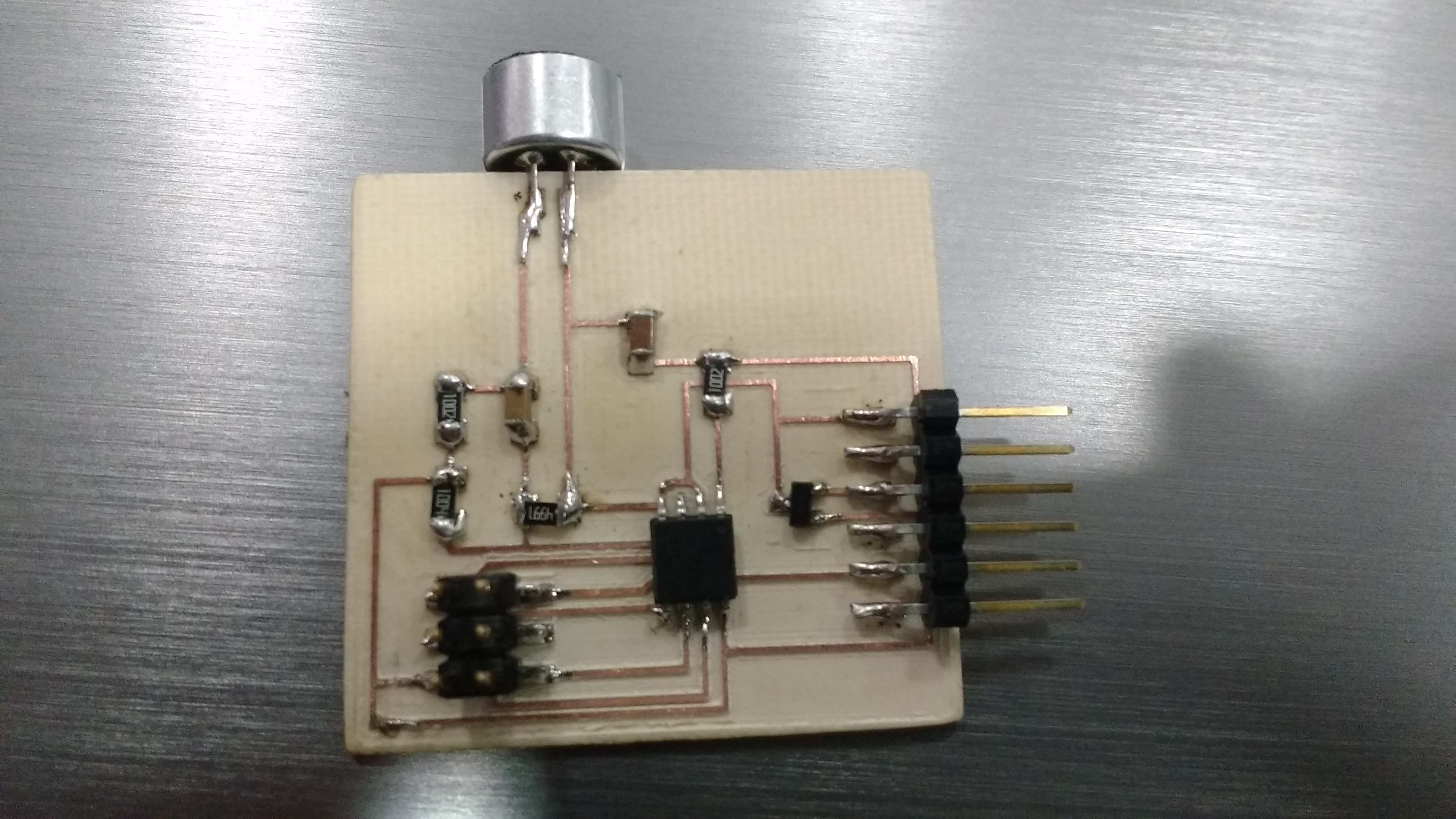
And when I finished soldering all the components the board looks like this.
The program of the board I did with my ISP and the code for this pourpose.
nemo@NEMOSTATION:~/Downloads/Hello45$ sudo make -f hello.txrx.45.make program-usbtiny
avr-gcc -mmcu=attiny45 -Wall -Os -DF_CPU=8000000 -I./ -o hello.txrx.45.out hello.txrx.45.c
avr-objcopy -O ihex hello.txrx.45.out hello.txrx.45.c.hex;\
avr-size --mcu=attiny45 --format=avr hello.txrx.45.out
AVR Memory Usage
----------------
Device: attiny45
Program: 558 bytes (13.6% Full)
(.text + .data + .bootloader)
Data: 201 bytes (78.5% Full)
(.data + .bss + .noinit)
avrdude -p t45 -P usb -c usbtiny -U flash:w:hello.txrx.45.c.hex
avrdude: AVR device initialized and ready to accept instructions
Reading | ################################################## | 100% 0.00s
avrdude: Device signature = 0x1e9206 (probably t45)
avrdude: NOTE: "flash" memory has been specified, an erase cycle will be performed
To disable this feature, specify the -D option.
avrdude: erasing chip
avrdude: reading input file "hello.txrx.45.c.hex"
avrdude: input file hello.txrx.45.c.hex auto detected as Intel Hex
avrdude: writing flash (558 bytes):
Writing | ################################################## | 100% 0.56s
avrdude: 558 bytes of flash written
avrdude: verifying flash memory against hello.txrx.45.c.hex:
avrdude: load data flash data from input file hello.txrx.45.c.hex:
avrdude: input file hello.txrx.45.c.hex auto detected as Intel Hex
avrdude: input file hello.txrx.45.c.hex contains 558 bytes
avrdude: reading on-chip flash data:
Reading | ################################################## | 100% 0.66s
avrdude: verifying ...
avrdude: 558 bytes of flash verified
avrdude: safemode: Fuses OK (E:FF, H:DF, L:62)
avrdude done. Thank you.
Finally I used python3 to run the program that captures the data, I did some modifications of code directly in the python code. The programs was called hello.txrx.45.py
Here some fragments and samples:
try:
# for Python2
from Tkinter import *
except ImportError:
# for Python3
from tkinter import *
#import Tkinter
#from Tkinter import *
import serial
And this too:
#if (len(sys.argv) != 2):
#print ("command line: hello.txrx.45.py serial_port")
#sys.exit()
#port = sys.argv[1]
port = '/dev/ttyUSB0'
#
# open serial port
#
ser = serial.Serial(port,9600)
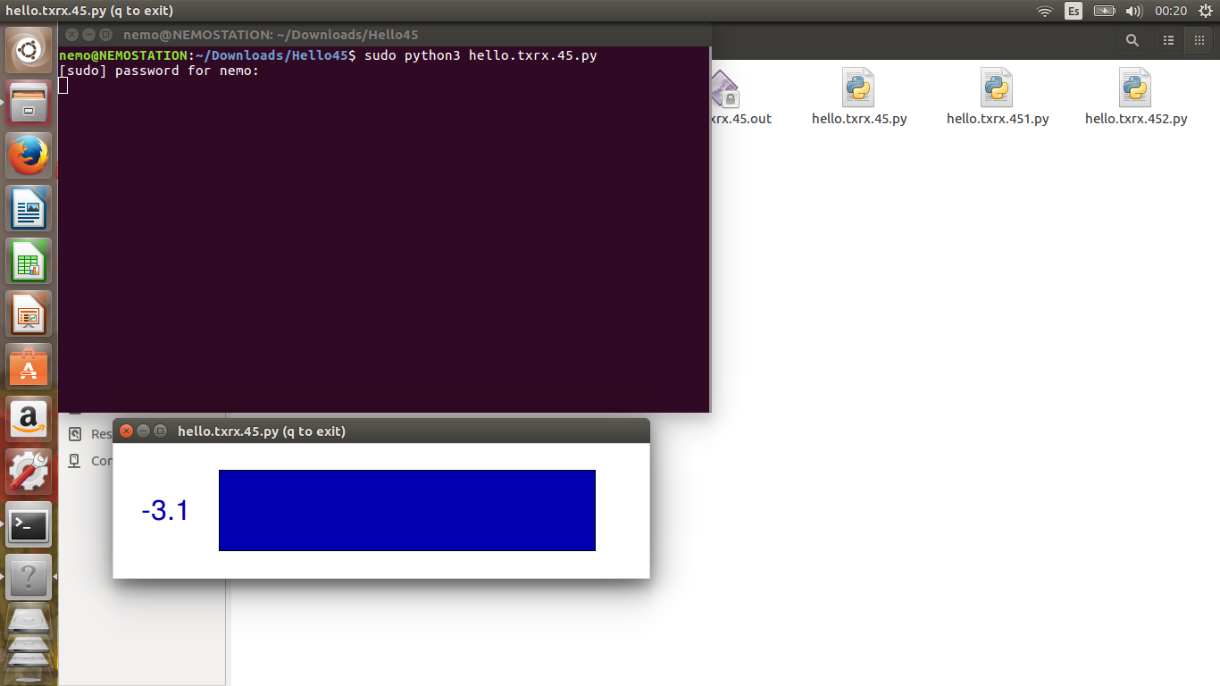
Finally I run this command:
nemo@NEMOSTATION:~/Downloads/Hello45$ sudo python3 hello.txrx.45.py
And here is the result of this command measurig the sound that microphone gets to the Attiny45.
Here some fragments and samples:
try:
# for Python2
from Tkinter import *
except ImportError:
# for Python3
from tkinter import *
#import Tkinter
#from Tkinter import *
import serial
And this too:
#if (len(sys.argv) != 2):
#print ("command line: hello.txrx.45.py serial_port")
#sys.exit()
#port = sys.argv[1]
port = '/dev/ttyUSB0'
#
# open serial port
#
ser = serial.Serial(port,9600)
Finally I run this command:
nemo@NEMOSTATION:~/Downloads/Hello45$ sudo python3 hello.txrx.45.py
And here is the result of this command measurig the sound that microphone gets to the Attiny45.
Here is the code in text mode in linux to run the python code
nemo@NEMOSTATION:~/Downloads/hello45Mic$ sudo python2 hello.mic.45.py /dev/ttyUSB0
[sudo] password for nemo:
from Tkinter import *
import serial
NX = 500
NY = 500
nloop = 100
path = []
baseline = 0
baseline_filt = 0.01
gain = .2
def idle(parent,canvas):
global path, baseline
#
# idle routine
#
# look for framing
#
byte2 = 0
byte3 = 0
byte4 = 0
while 1:
byte1 = byte2
byte2 = byte3
byte3 = byte4
byte4 = ord(ser.read())
if ((byte1 == 1) & (byte2 == 2) & (byte3 == 3) & (byte4 == 4)):
break
path = []
for i in range(nloop):
lo = ord(ser.read())
hi = ord(ser.read())
if (hi < 2):
reading = 512 + 256*hi + lo
else:
reading = 256*hi + lo - 512
baseline = baseline_filt*reading + (1-baseline_filt)*baseline
value = NY/2 + gain*(reading - baseline)
path.append(i*NY/float(nloop))
path.append(value)
canvas.delete("path")
canvas.create_line(path,tag="path",width=3,fill="#00b000")
parent.after_idle(idle,parent,canvas)
#
# check command line arguments
#
if (len(sys.argv) != 2):
print "command line: hello.mic.45.py serial_port"
sys.exit()
port = sys.argv[1]
#
# open serial port
#
ser = serial.Serial(port,9600)
#
# start plotting
#
root = Tk()
root.title('hello.mic.45.py')
root.bind('q','exit')
canvas = Canvas(root, width=NX, height=NY, background='white')
canvas.pack()
root.after(100,idle,root,canvas)
root.mainloop()
The results obtained with the first board no have succesful results as shown in video below.
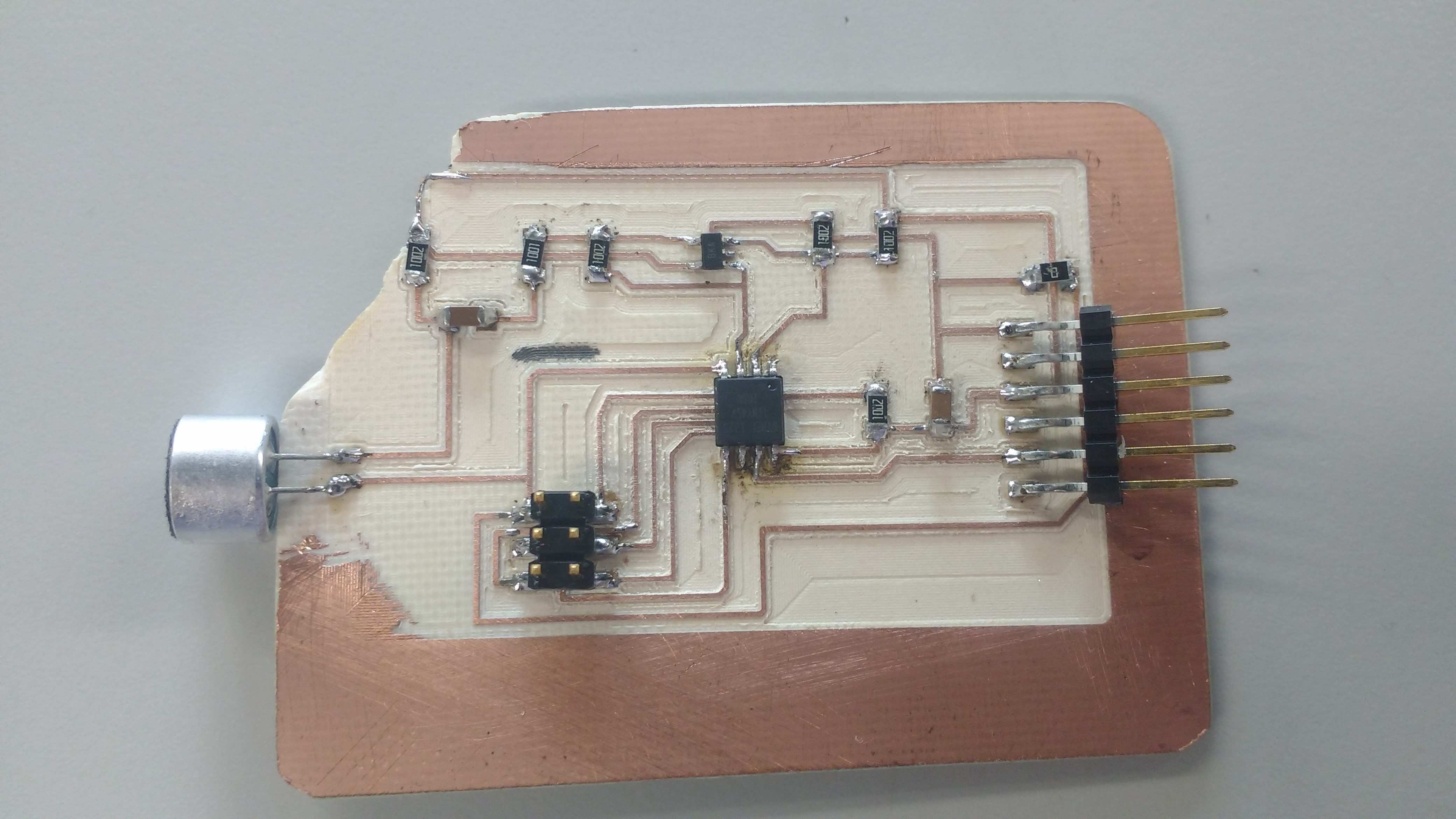
So, to get better results i modify the board adding an OpAmp to the original board. I made other board and i test it with the same python code, obtain best results.