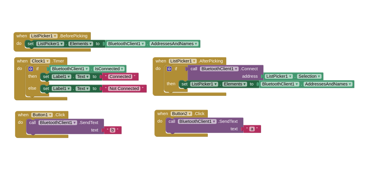
This week assignment require us to make application that interfaces at least one input or output. I made a simple android app using MIT APP Inventor 2 that sends letter 'a' if button 1 is pressed and letter 'b' if button 2 is pressed. The app communicates to my week 6 board via the HC-06 bluetooth to serial module.
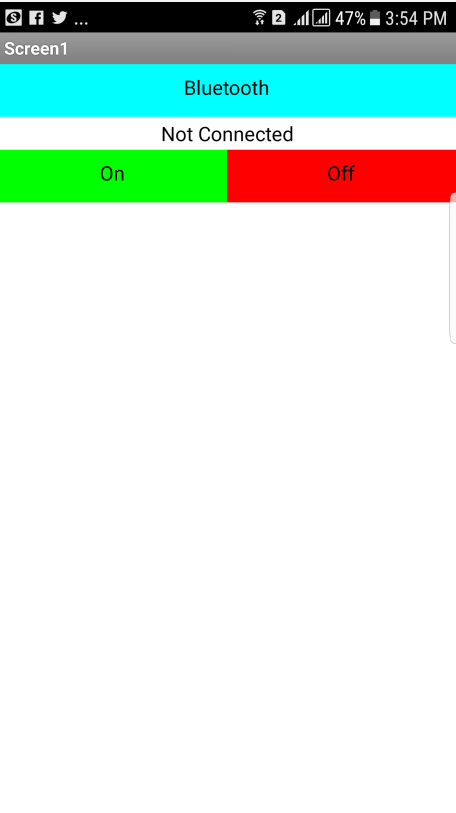
At the begining I made a simple application to get used with app after learning from this nice tutorial by Magesh Jayakumar. So I made a simple anrdiod app that has 3 buttons which are:
Bluetooth: connect the bluetooth to the bluetooth to serial module that is connected to the board that has the LED.
On: when clicked sends character a to turn on the LED.
OFF: when clicked sends character b to turn on the LED.
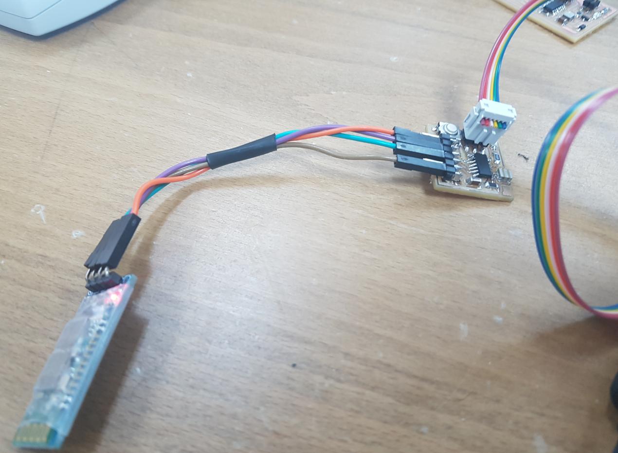
First I tested the app on my week 6 board that has serial interface. I connected the HC-06 bluetooth module to the board using female wires as shown below:
Then I edited Neil's serial bus code and made it switch on the LED if letter 'a' is received and switch it off if letter 'b' is received. The below video shows the system working:
With this I am ready to work on the final project mobile app!
My final project FabRover has 7 different electronic boards or lets call them nodes. There 3 main type of boards which are the main board, the motors board and the sensor board. The doucmentation of the motors board and sensor board can be found at week 10 and week 13 respectively while the documentation of the main board will be in this week.
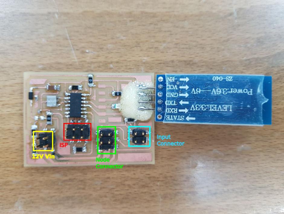
The main board as shown below has a bluetooth connection via serial communication, I2C port, motor node port and sensor node port and of course ISP port that is also meant for supplying the 5V voltage for the MCUs of all the boards.
As seen in the picture, the HC-06 bluetooth module pads borke and go removed from their place because I was trying to adjust the orinetation of the module after soldering it, so I used glue-all max glue to stick it back to its place.
In general, the anrdoid app should control the movement of the FabRover wheels as well as gets the readings from the LDR board. I have 6 wheels to control but I will start with controling one wheel and getting the readings from the LDR. So I need to desing an app that do the following:
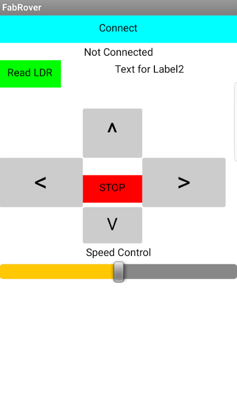
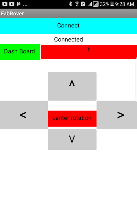
I designed the first draft of the app to have a simple control buttons that control the FabRover as well as displaying the readings of the LDR. The below screenshot shows the interface of the app:
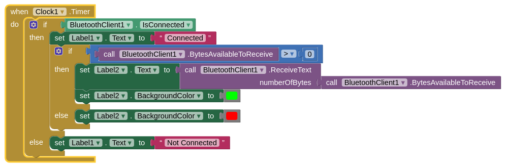
This time I am sending and receiving data from the board the HC-06 is connected to which is in this case the main board. The above blocks work as the following:
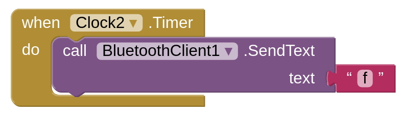
On the other hand, from the main board side, I programmed it to send a letter "a" when a letter "f" is received which is done every 1 ms using another clock on the app as shown below:
The below video shows the app working and label color is being changed every time the app receives something from the main board.
With this I am done with displaying the data on the app now the only thing remaining is controling the motors from the app itself. I started with the controling the DC motors, the idea was to make the motor move in a given direction while the button on the app is pressed down and to stop it after releasing the button. Luckily there are blocks for pressing down and relesing the buttons in MIT app inventor which are when touch down and when touch up. Most of the youtube tutorials about controling motors in youtube using MIT app inventors depends on the click event of the button because it is easy to implement so I searched more about this issue and found a the solution in this nice tutorial.
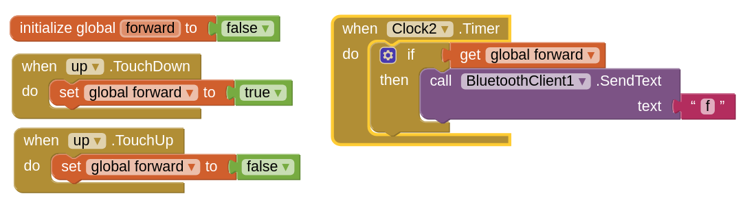
They used the touch down event of the canvas to set a golbal variable to true then a clock that excute whatever inside it when this specific global variable is set to true and finally a touch up event that set the global variable that is assocated with the button to false to stop excuting whatever inside the conditional clock event. The below screenshot shows how I applied this technique to the ^ button in the app to control the DC motor.
This system consists of 3 main components which are the main board that has the bluetooth module, the motor board and the app. The main board has two serial ports one of them is for communicating with the app and one for communicating with the motor board. The code that is in the main board does nothing but forwarding the message sent via the app.
I also uploaded a video demonstrating the functionality of the app.
Finally, I made a serial communications between the main board and three wheels. The main board was actining as serial bridge with two serial ports. It is connected to the mobile app via serial port one (PA1 & PA2) and connected to the 3 wheels via serial port two (PA4 & PA6). So the main board receives characters from the mobile app and forward them to the 3 wheels.
Then each wheel acts according to the characters it receives from the mobile app. The communication protocol is shown in the table below:
| Mobile App | Character | Wheel 1 | Wheel 2 | Wheel 3 | Rover |
|---|---|---|---|---|---|
| Up Button | 'f' | Forward | Forward | Forward | Move Forward |
| Down Button | 'b' | Backword | Backword | Backword | Move Backword |
| Left Arrow | 'l' | left | Forward | Forward | Turn Left |
| Right Arrow | 'r' | right | Forward | Forward | Turn Right |
| Mid Button | 'c' | right+forward | Forward | left+forward | Center Rotation |
| Nothing Pressed | 's' | idle | idle | idle | idle |
I implemented this program in the app using the following blocks which are based on the continuous control of the wheel that I did before:
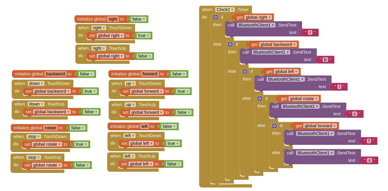
The final app consisits of 4 main buttons and label that shows the received charater that is forwarded from the main board.
The main board forwards the received characters from the app to the wheels using the following code:
while (1) {
get_char(&serial_pins, serial_pin_in, &chr); // receive characters from the mobile app
 if (chr > 0)
 {
     output(serial_direction, serial_pin_out);
     output(serial_direction, serial_pin_out1);
     put_char(&serial_port, serial_pin_out, chr);
     put_char(&serial_port, serial_pin_out1, chr);

   else
 {
    input(serial_direction, serial_pin_out);
    input(serial_direction, serial_pin_out1);
 }
Finally each wheel will move according to what the character it receives. I programmed 5 modes of movements which are moving forward, backword, left, right and center rotation. The below video shows me using the mobile app to control the rover to perform these modes of operations: