Interfacing Bluetooth and OLED
So this week, I would be building an android application that uses bluetooth to control the OLED display. So to start with that, I had to build up the bluetooth interfacing with arduino (and then with Satsha kit).
I found lot of DIY Intructables that gives detailed steps to get started with bluetooth integration to control LED.
I followed this Instructable to get started with OLED and to control via bluetooth using this Instructable
I also tried out OLED display using arduino sometime back; I wanted to use arrow icons on the display. So I designed an arrow in photoshop and converted it into bitmap binary code. I used this link for this conversion. This is the arrow image I designed and its resolution is 32 x 16. Its really small!!
I wrote the arduino code based on the instructables I read,
#include < Adafruit_SSD1306.h >
#include < SoftwareSerial.h >// import the serial library


#define OLED_RESET 4
Adafruit_SSD1306 display(OLED_RESET);

static const unsigned char PROGMEM logo16_glcd_bmp[] =
{ 0x00,0x00,0x00,0x00
,0x00,0x00,0x00,0x00
,0x00,0x00,0x02,0x00
,0x00,0x00,0x03,0x00
,0x00,0x00,0x03,0x80
,0x00,0x00,0x01,0xc0
,0x00,0x00,0x01,0xe0
,0x0f,0xff,0xff,0xf8
,0x0f,0xff,0xff,0xf8
,0x00,0x00,0x01,0xe0
,0x00,0x00,0x01,0xc0
,0x00,0x00,0x01,0x80
,0x00,0x00,0x03,0x00
,0x00,0x00,0x02,0x00
,0x00,0x00,0x00,0x00
,0x00,0x00,0x00,0x00
,0x00,0x00,0x00,0x00
,0x00,0x00,0x00,0x00

 };

#if (SSD1306_LCDHEIGHT != 32)
#error("Height incorrect, please fix Adafruit_SSD1306.h!");
#endif


SoftwareSerial Genotronex(10, 11); // RX, TX
int ledpin=13; // led on D13 will show blink on / off
int BluetoothData; // the data given from Computer

void setup() {
  // put your setup code here, to run once:
  // Genotronex.begin(9600);
  // Genotronex.println("Bluetooth On please press 1 or 0 blink LED ..");

  Genotronex.begin(9600);
  Genotronex.println("Bluetooth On please press 1 or 0 to direct ..");
  // dht.begin();
  display.begin(SSD1306_SWITCHCAPVCC, 0x3C);  // initialize with the I2C addr 0x3D (for the 128x64)
  pinMode(ledpin,OUTPUT);
}

void loop() {
  // put your main code here, to run repeatedly:
   if (Genotronex.available()){
      display.display(); //I love Adafruit :D
    BluetoothData=Genotronex.read();
    if(BluetoothData=='1'){   // if number 1 pressed ....
      digitalWrite(ledpin,1);
      Genotronex.println("LED  On D13 ON ! ");

      display.clearDisplay();   // Clear the buffer.

      display.drawBitmap(0, 0,  logo16_glcd_bmp, 32, 32, 1);
      display.display(); //I love Adafruit :D
      // delay(1000);


    }
    if (BluetoothData=='0'){// if number 0 pressed ....
      digitalWrite(ledpin,0);
      Genotronex.println("LED  On D13 Off ! ");
      display.clearDisplay();   // Clear the buffer.
      display.setTextSize(1);
      display.setTextColor(WHITE);
      display.setCursor(0,0);
      display.println("#Distance");
      // display.setCursor(20,0);
      // display.println(10);
      display.setTextSize(1);
      display.setCursor(0,10);
      display.println("#Address");

      display.display(); //I love Adafruit :D
    }
  }
  delay(100);// prepare for next data ...
}
I was able to get it functioning, but there seems to be some junk data coming along with the image(arrow), after the image. I will need to fix it later.
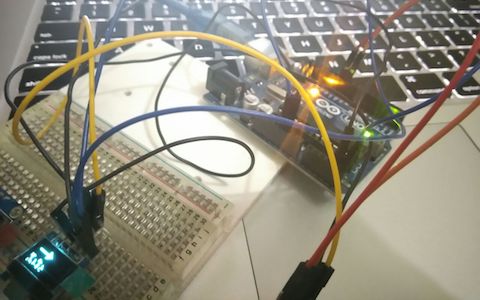
I used adafruit SSD1306 module to handle displaying on the OLED. I didn't quiet invest my time to the working details of this module though. The following is a a picture of the OLED displaying via bluetooth.
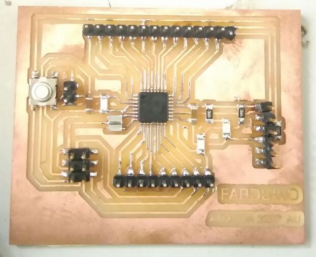
Designing Satsha Kit
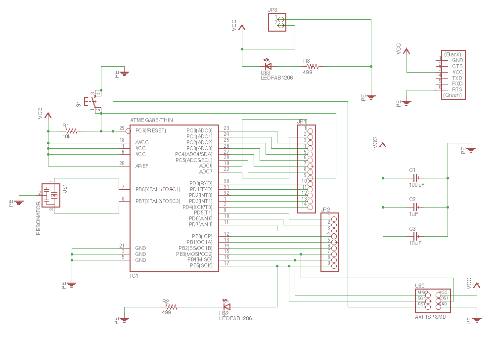
Since this weeks assignment includes me to work with a board I designed, I decided to build Satsha kit. The following is the schematic I made based on Daniele Ingrassia's work.
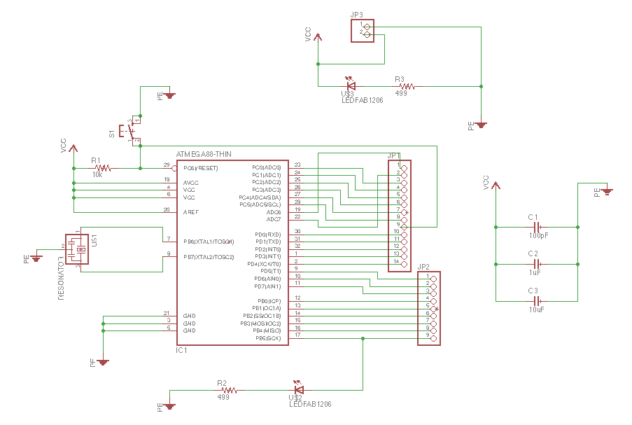
I also referred Rahul's documentation of satsha kit, he informed me of his challenges, so I added a couple of pins for vcc and gnd; added pins for ftdi as well. Routing was getting challenging, so I deleted the Rx, Tx on the FTDI that helped me to route successfully manually.

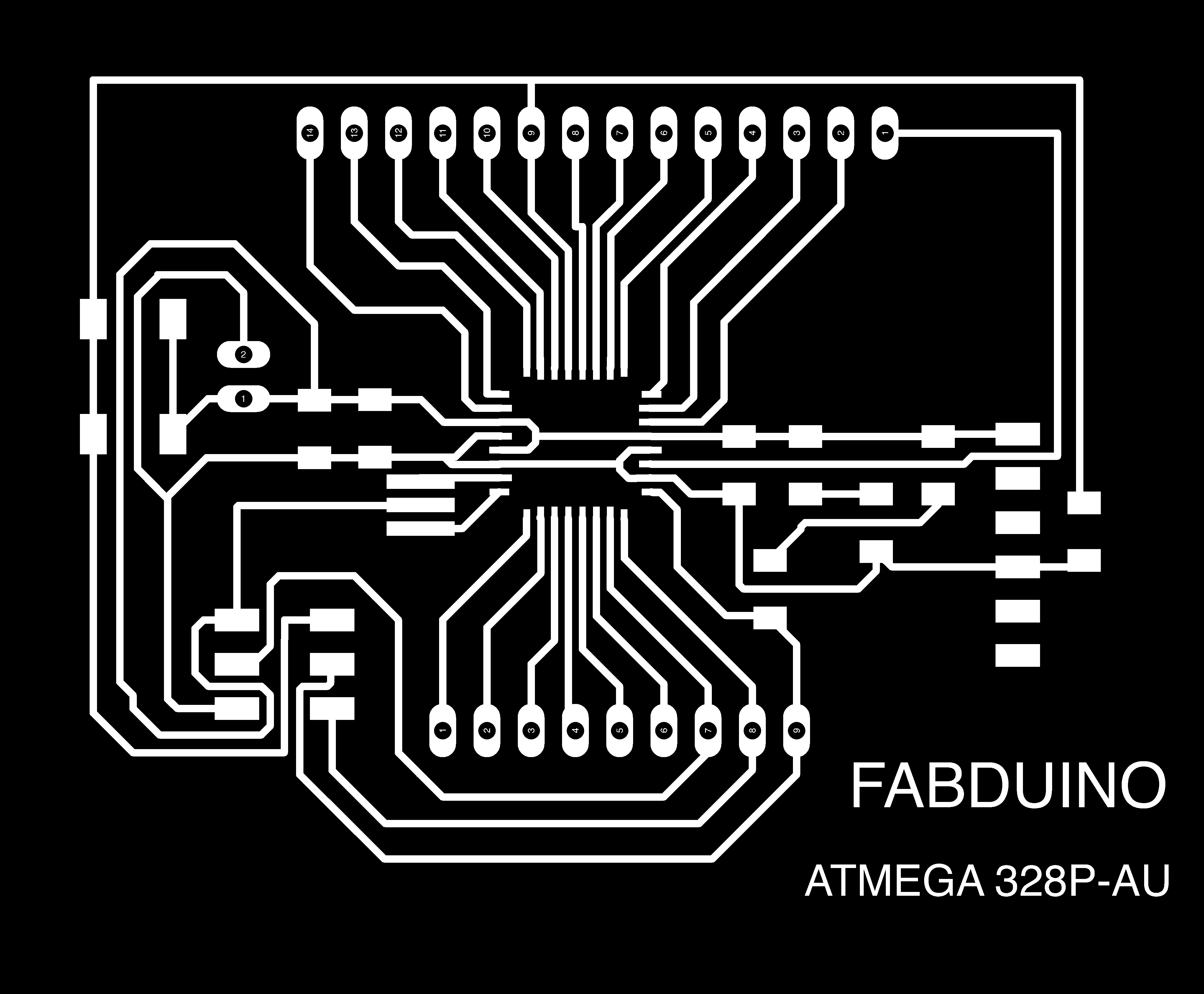
Milling Satsha Kit
I exported the board trace and cut outline for the Fabduino board I created.
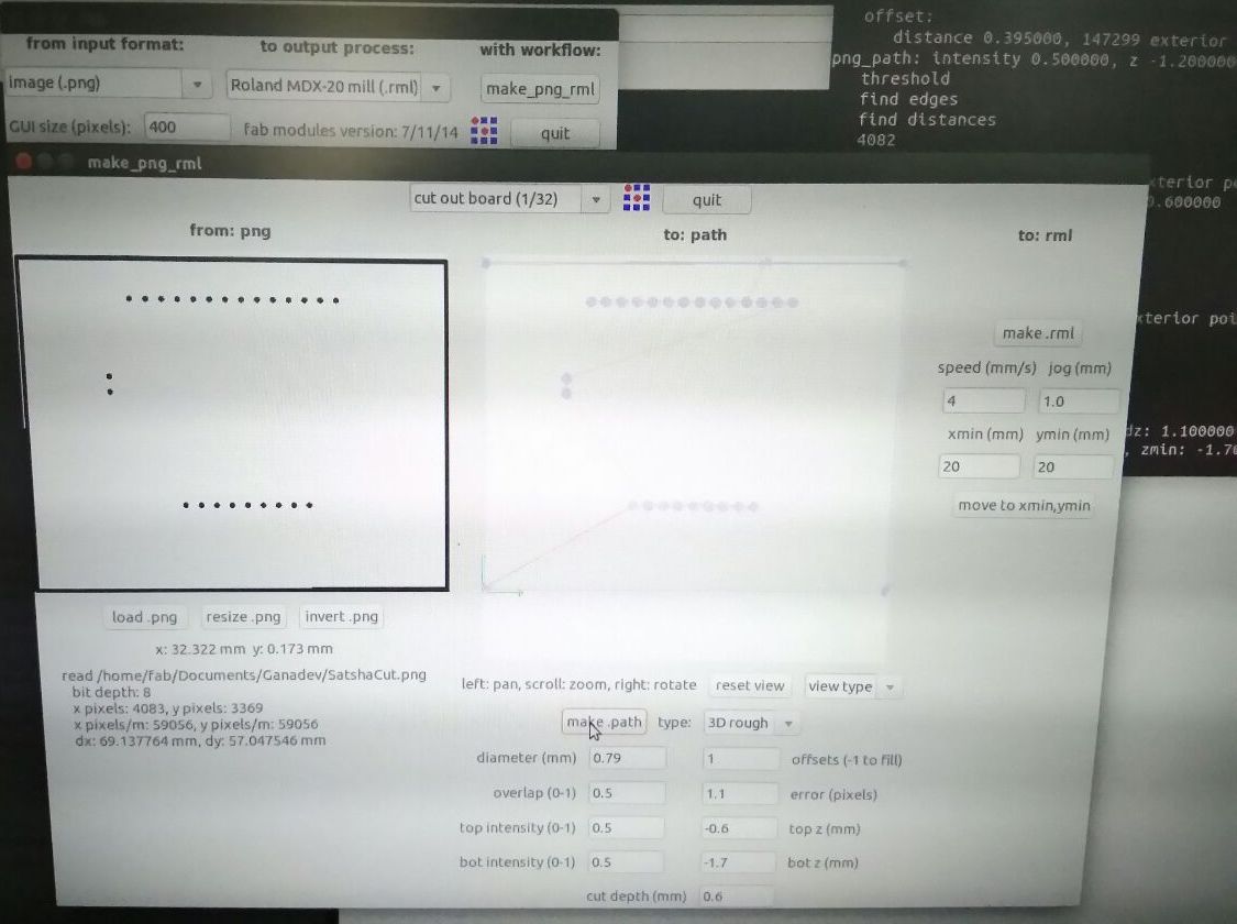
I used the fab modules to mill my design. Following are the screenshots I took when initiating the milling and cutting.

After milling and cutting out the board,
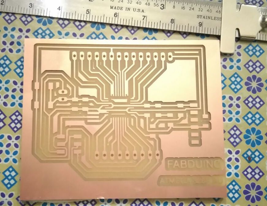
There are some traces that were not separated. I had to manually cut out those traces.

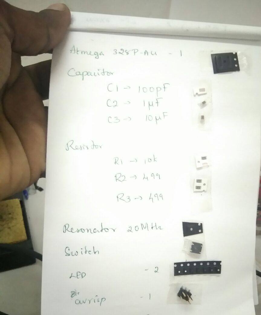
Assembling the board
After collecting the components,
Soldering was challenging as the traces were small and so close, and but was able to get it all assembled neatly.

MIT App Inventor
I used MIT App Inventor to create my android application because that was the easiest way to build it. I started off with some tutorials, and found the block really easy to work with.
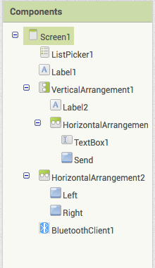
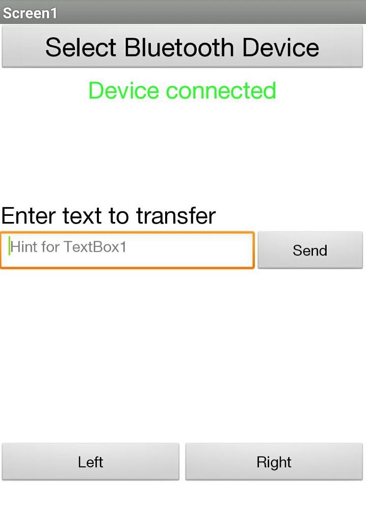
There are 2 sections in App Inventor, one is Designer and the other is Blocks.The Designer section, we select the features we want to work with and the UI elements. There is hierarchy to some elements as well which lets us put other elements in it. I seen this in the Layout element. The invisible component here is the BluetoothClient element which I need for working with Bluetooth connections.
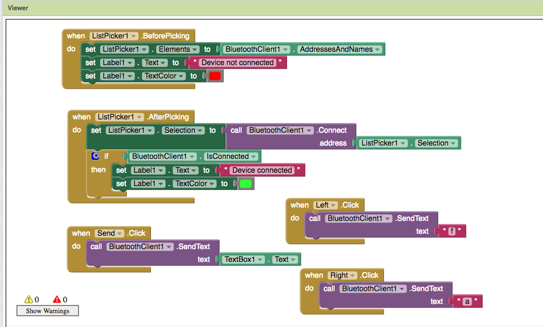
The Blocks section lets us work with the logic behind the UI elements. Its all drag and drop, you would get an idea which type of blocks fits where based on the shape of the block. The following is the screenshot of my work in MIT App Inventor.
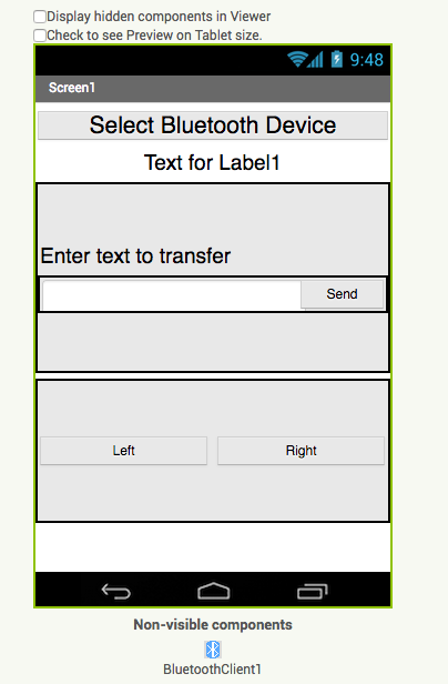
The app allows to connect with a bluetooth module, and send control signals to it. The following is a screenshot of the mobile app.
Programming on Satsha kit
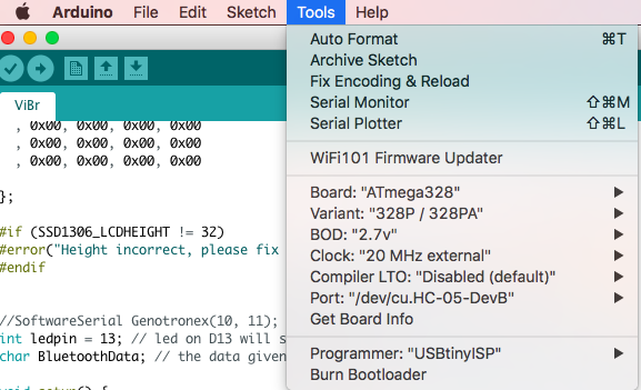
To start programming on Satsha kit, I used my fabISP to burn the bootloader, which can be done on Arduino IDE itself. You would need to add MiniCore to board manager.

Then Go to Tools, since my board has an Atmega 328P-AU, I selected the same, set the external clock to 20MHz and changed the programmer to USBtinyISP. The rest I made no change and ran Burn Bootloader.
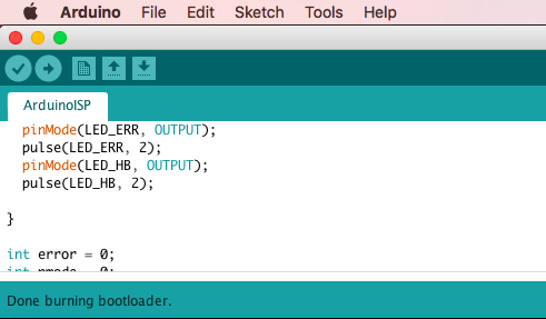
And wait for the confirmation !!
I redid the Arduino setup on Satsha kit to test out the code. It did not quiet work as earlier and details on that is mentioned later down the documentation.

Since the problem was with Serial printline, I commented those lines; changed from SoftwareSerial to the default Serial and made some more updates on the code.
#include < Adafruit_SSD1306.h >
//#include < SoftwareSerial.h >// import the serial library


#define OLED_RESET 4
Adafruit_SSD1306 display(OLED_RESET);

static const unsigned char PROGMEM logo16_glcd_bmp[] =
{ 0x00, 0x00, 0x00, 0x00
  , 0x00, 0x00, 0x00, 0x00
  , 0x00, 0x00, 0x02, 0x00
  , 0x00, 0x00, 0x03, 0x00
  , 0x00, 0x00, 0x03, 0x80
  , 0x00, 0x00, 0x01, 0xc0
  , 0x00, 0x00, 0x01, 0xe0
  , 0x0f, 0xff, 0xff, 0xf8
  , 0x0f, 0xff, 0xff, 0xf8
  , 0x00, 0x00, 0x01, 0xe0
  , 0x00, 0x00, 0x01, 0xc0
  , 0x00, 0x00, 0x01, 0x80
  , 0x00, 0x00, 0x03, 0x00
  , 0x00, 0x00, 0x02, 0x00
  , 0x00, 0x00, 0x00, 0x00
  , 0x00, 0x00, 0x00, 0x00
  , 0x00, 0x00, 0x00, 0x00
  , 0x00, 0x00, 0x00, 0x00

};

#if (SSD1306_LCDHEIGHT != 32)
#error("Height incorrect, please fix Adafruit_SSD1306.h!");
#endif


//SoftwareSerial Genotronex(10, 11); // RX, TX
int ledpin = 13; // led on D13 will show blink on / off
char BluetoothData; // the data given from Computer

void setup() {
  // put your setup code here, to run once:
  Serial.begin(9600);
//  Serial.println("Bluetooth On please press 1 or 0 to direct ..");
  display.begin(SSD1306_SWITCHCAPVCC, 0x3C);  // initialize with the I2C addr 0x3D (for the 128x64)
  pinMode(ledpin, OUTPUT);
//  BluetoothData = '0';
}

void loop() {
  if (Serial.available()) {
    display.display(); //I love Adafruit :D
    BluetoothData = Serial.read();
//    Serial.println(BluetoothData);
    switch(BluetoothData) {
      case 'a': digitalWrite(ledpin, 1);
//              Serial.println("LED  On D13 ON ! ");
              display.clearDisplay();   // Clear the buffer.
              display.drawBitmap(0, 0,  logo16_glcd_bmp, 32, 32, 1);
              display.display();
              break;
      case 'f': digitalWrite(ledpin, 0);
//              Serial.println("LED  On D13 Off ! ");
              display.clearDisplay();   // Clear the buffer.
              display.setTextSize(1);
              display.setTextColor(WHITE);
              display.setCursor(0, 0);
              display.println("#Distance");
              // display.setCursor(20,0);
              // display.println(10);
              display.setTextSize(1);
              display.setCursor(0, 10);
              display.println("#Address");

              display.display();
              break;
      default: break;
    }
  }
//  delay(100);// prepare for next data ...
}
The control signals were 'a' and 'f' to change the content displayed on the OLED. A video I took to show case that.
Challenge Faced
The same code I wrote which worked in arduino failed to work in Satsha kit I build. It was not working promptly; I found out that other data were being received other than 0 and 1 which was randomizing the output.
The following video kind of shows the problem, the output was changing very fast.
I used the serial monitor (BlueTerm)in my mobile phone to see that the following line of code was actually interfering with the data flow,
Serial.println("Bluetooth On please press 1 or 0 to direct ..");
What I found was that the Serial print line was getting acknowledged as data to be processed. These lines where overlapping my control signals and since I havent written code to process these, it was kind of ignoring (or processing really fast) the control signals I'm sending via my mobile app or arduino serial monitor.
Eventhough the solution was pretty easy, it took my a lot of time to figure it out. :(
Design Files and Source Code
Arrow.jpg
SatshaTrace.png
SatshaCut.png
Satsha.sch
Satsha.brd
ViBr.ino
bluetooth.ino
ViBr.aia