8. EMBEDDED PROGRAMMING
Index
- Assignment
- Introduction
- The Datasheet
- Key Features
- Other things i learned about the microcontroller
- Low Fuse bytes
- High Fuse bytes
- Programming with C
- Setting up the C programming environment
- The LED blink program
- Making the breakout board
- The switch program
- Timer/counter program
- Interrupts program
- Making some noise with AVR
- Making a piano with AVR
- Programming with arduino
- Blinking the LED
- Tools Required
- Step by step
- Button program
- Summary
A. Assignment
- Read a microcontroller data sheet.
- Program your board to do something, with as many different programming languages and programming environments as possible.
- Optionally, experiment with other architectures.
B. Introduction
This week we are working on embedded programming. I have a basic working experience with
arduino and
i have done C programming before but AVR C is new to me. This week i am looking forward to learn more
about
them.
I think this is good time to brush up my arduino skills and build a solid background on AVR C
programming.
There are lots of tutorials and documents available for AVR as it is one of the most popular MC
avaiable. Its
hard if
you have no documentation and if there is too much documentation. I think the case of avr programming is
the
later, where you
have tutorials and samples all around the web. You need to be picky on choosing resources for learning.
My way
of doing this
is to find the best book you can get on the subject and do as the author instructs. Here also i am
following the
same.
After a serious of discussions and search i concluded on the book:
Make: AVR
Programming
by Elliot Williams.
This book is something which i would suggest for someone who want to start with AVR C programming, if
you have
some experiance with
arduino. If you want to learn arduino programming, i would suggest
Getting Started with
Arduino
– Massimo Banzi
c. The datasheet
You can find the datasheet here. If you are like me, reading a datasheet for the first time, you maight be thinking; why this huge documentaions for such a small chip :P. But once you get to know the power of this chip you will apperaciate the datasheet. As Elliot Williams, the author of Make: AVR Programming, says, use the datasheet as a dictionary. Dont try to learn from it when you are starting up. Get started and then use the datasheet for better understanding. If you are a beginer and just want to get started, you can skip this details for now and try out the programms and later once you have a basic idea about it you can come in and take a look at this.
First in the datasheet you will find the pin configurations of the chip, followed by the
descriptions of each
pin. These pins are grouped into different categories, Port B(PB0 to PB3), PortA the you have VCC,
Ground Reset pins.
Both PortA and PortB pins are IO pins and the difference i think is that Port A has alternate functions
as ADC, timer, couner, comparator
etc.
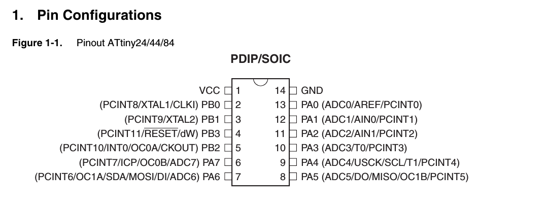
Pin configurations of attiny44
Then you have details on the architecture clock etc. The following is a summary of the specifications
and utilities of the chip
- Architecture: RISC(Reduced Instruction Set Computer)
For more details about this acrhitecture refer wikipedia - Speed - upto 20mhz at 4.5 - 5.5 V (upto 10mhz at 2.7 - 4.5 V)
This means that the chip can process 20000000 instructions per second. Your PC cam process 100 to 1000 times more instructions. - Power consumption: Low
This chip takes only very low power for its operation. - Number of registers: 32 8bit registers
Register is like a memory location uses to store data. 8 bit means a number is stored with a maximum of 8 bits, ie a byte. You cant store a number bigger that a byte in this memories - Flash momory: 4 Kilo Bytes
This means that we can load programs of maximum size of 4 KB in this chip - 56 bytes In system programmable EEPROM, 256 bytes of EEPROM
These are other kinds of memory - Clock: internal- 1mhz and external upto 20 mhzs
Clock speed determinies the speed of the processor - Digital Communication Peripherals: 1-SPI, 1-I2C
- Capture/Compare/PWM Peripherals: 11 CCP4
- Comparators: 1 NOS
- Operating Voltage Range (V): 1.8 to 5.5
- Programmable Watchdog Timer with Separate On-chip Oscillator
- debugWIRE On-chip Debug System
- In-System Programmable via SPI Port
- Internal and External Interrupt Sources
- Enhanced Power-on Reset Circuit
- Programmable Brown-out Detection Circuit
This means we can run a different funciotn when the chip is operated at sub optimal voltages. - Internal Calibrated Oscillator
c1. Key features
- A microcontroller is a small computer, with RAM, processor and pereferals etc. We can program the controller to do a task. It cannot multitask like our normal computer.
- MC is a digital device, it brings out the control operation by setting pins high( 5v) or low(0 volt). It can also take in voltages as input from sensors. There are specific pins in the chip which can be used for this purpose. Not every pin can be used for anolog input. These pins are marked ADC in the diagram.
- Except a few almost all pins can be used as either digital input or digital output. This can be done pragmatically.
-
Programming the MC
There is a special pin called 'RESET' this is critical in programming the MC. This pin is normally pulled high. If we pull the pin low for a few clock cycle(specific for the MC) the MC enters the programming mode and listens on the ISP pins. ISP pins are MISO( output from MC, after flashing code verification is done through this), MOSI ( input to the MC, programs are send to flash memory of the MC through this pin). SCK (clock, this pins is for syncing the clocks in the programmer and the MC being programmed). There is a VCC and GND pins also, the VCC can be used to power the MC from the PC where the programmer is connected.
Grounding the RESET pin momentarily will restart the MC. This process can be made use of in craating a reset button for our mc. -
CLock
Like computers clock is very essential for the MC also. Most AVR MC comes with an internal clock. For some MC, the clock is accurate and for some others they are not.A clock is powered by a resonator or a crystal. For attiny 45 it has a accurate clock with high speed, whereas the attiny44 has a less accurate and slow clock. The clock determines the speed of the MC. The higher the clock the higher the speed. But there is a limit for the clock speed for the MC, ususlly 20 mHz. For MC with less accurate and slow internal clock its a good option to use an external crystals/ resonator. Resonators are usually LC circuits whereas crystals are made of quatz. Crystals are much more accurate compared to the resonators. It is a good practice to use an external clock if we need accuracy. If using a resonator, make sure that you put it as close as possible to the clip to avoid noise.
Resonators are non polar components, you can connect them in any way in the circuit. The MC pins XATL1 and XATL2 are the point of connection for the crystal. resonator. -
Registers
The MC pins usually comes in group usually of 8. eg: PB0, PB1, PB2 etc. These are internal registers associated with each pin. usually 1 byte for 8 pins thus i bit per pin. We can set the pins to be input of output by toggling these bits. 0 for input and 1 for output. In AVR C, we can refer to the pin groups by DDRx where x if A, B etc ( from PB, PA ...). Eg: DDRA = 0b00000001; will set all pins in group A except the first one to input. The first one is set to output. 0b is for binary, 0x means hex. Remember setting the DDRx(DAta Direction Register) will only configure the pins to be output or input but does not actually output any thing. To output something, we need to use the PORTx register. To pull high the first pin, use PORTA = 0b00000001;.If you have not configured a pin to be output, the PORT setting will not work. IF you use led in this pins you will see that the led lights, but it will be very dim. Eg. DDRA = 0b00000001; and PORTA = 0b000011; will not turn on the second pin.
For inputs we use PINx. -
Voltage and Voltage drop
One early confusion i had was about voltage and voltage drop. If i connect an LED and resistor in series to a battery, the resistor drops voltage across it. Maybe 2 volt depending on its resistance and the rest 3v goes to the LED. This does not mean that the voltage in the whole circuit is now zero. So voltage is still 5 volt only, but voltage drop after the led is zero. If you are like me you should'nt imagine voltage like 5 balls, 2 you give to resistor and 3 to led and you have noting returning to the circuit. This concept is wrong. The voltage only depends on the type of power supply and not on the components you connect in the circuit. One more thing to remember is that you should only measure voltage drops if the circuit is closed. Ie, components only drop voltage when they are in a closed circuit. If you open a circuit and measure the end terminals voltages you will always get the source voltage. In such a situation don't misunderstand that the components are not droping any voltage, rather it is because the curcuit is not closed, you get such a result. To correctly measure the voltage drops, close the circuit and measure the voltage across the component.
In MC we have pull up resistors usually 10k, i use to think that if we put that huge resistance between the pin and the VCC, the pin gets negligable voltage only and how can it be called pull up??, but that is wrong. What ever resistance you put( not infinity) you will have the pin voltage to be 5 volt, but the current is limited by the resistor. -
Fuse bits
Fuse bits are like critical configuraions for the MC. We know that we can use inernal or esternal clock but how do we tell, the MC abt this. This is done using the fuse bits. By default the internal clock is used. It has a speed of 8 mHz in attiny44. These is a fuse bit called CKDIV8 which will divide the clock speed by 8 thus pulling down the speed to just 1 mHz. Lets dive deep into the fuse bits.
There are two sets of fuse bits: Low fuse bits and Hign fuse bits. Refer page 160 of datasheet.c3. Low fuse bytes
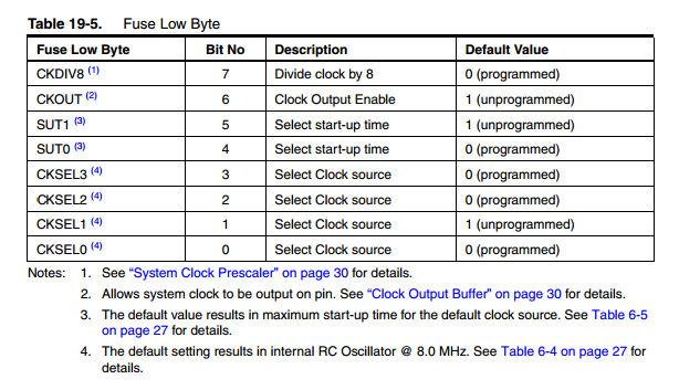
CKDIV8 This is the fuse which determines if the clock speed is scaled or not. It is often refered to as prescalar. If this is programmed( value 0 ) then the clock will be scaled down to a factor of 1/8, ie 8/8 = 1 mHz for internal resonator. Thus if we want the full 8 mHz we need to unprogram this fuse bit.
CKOUT This fuse bit can be programmed to enable system clock output on the CKOUT pin in the MC. This is useful if we need the MC clock to drive other circuits.
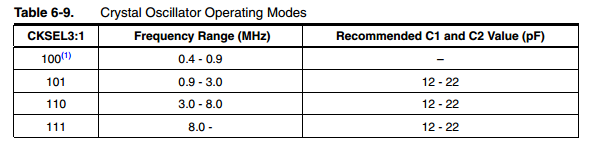
CKSEL3:1 These let the MC know the resonator we are using.
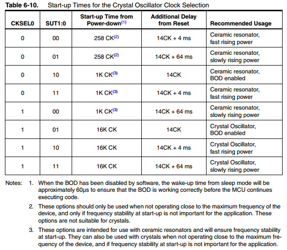
CKSEL, SUT1:0 This pair lets us choose the startup times. Refer the follwoing table.
c4. High fuse bytes
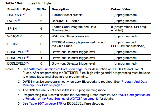
RDTDISBL If programmed, this will make the chip unprogrammable again. This is what we have done with the FABISP. We programmed this fuse and made it unprogrammable again.
DWEN This fuse bit enables debugging. Unprogram this for security
SPIEN Enables serial programming and data downloading when programed. It is programed by default
WDTON Enables watchdog
EESAVE EEPROM memory is preserved through the chip erase.
BOD 0-2 This is for blown out detection. This fuse helps detect low or high power beyond alowable levels and help turn on or off the MC saving it from damage.
Now you need to provide these fuse configurations during the flashing operaion to get the to work. Lets say the follwoing are the states we want.
CKDIV8 1
CKOUT 1
SUT1 0
SUT0 1
CKSEL3 1
CKSEL2 1
CKSEL1 1
CKSEL0 0
Thus Fuse Low Bye : 1101 1110
D E
To configure these in the MC run
avrdude -c usbtiny -p attiny -U lfuse:w:0xde:m
You can set high fuse using
-U hfuse:w:0xdf:m -
Interrupts
Interrupts are events requiring immediate attention, such as a button press. We can program the MC to do some specific task on such events. Thus on occurrence of such events the MC puts the regular processing in a task and move out to attend the interupt. This is basically done by defining a routane ( function) to be executed on specific interupt. Once the routane is complete, the MC returns to its normal operation. To enable interupt programming we need to enable Global Interrupt Enabled bit and the Interrupt Enable bit of the specific interrupt.
Interrupt Service Routine(ISR) of Intreupt Handler They are the routanes run on specific kind of interupt. -
Timers
We know that our MC has a clock which runs on configured rate. For attiny default is 8 mHz which is scaled down to a 1 mHz by the prescalar. Now the cpu is running at 1 mHz, if want to do something per second we can use the timers/ counters. Timers are a build in hardware which when enabled counts as per configured. We can ask the timer to count every clock cycle, every 8 clock cycle 64, 512 or 1024 clock cycles. But the timer is either 8 bit or 16bit, that is a 16 bit counter can count till 65535 only and an 8 bit one only the half of that. SO it is definite that your timer cant count till i million~ 1sec. So we can use the Prescalars. The pre-scalars are either 1,8,64,512 or 1024. If we configure the prescalar to 8 the counter will tick once every 8 ticks of the clock. Now we know the limit of out counter, we need to find the right prescalar which will give you enough values to count till a second. So we do : 1000000/ 65535 = 15.39 . The nearest prescalar is 64 (we cant take a smaller one). Now at every sec the counter value will be 1000000/64 = 15625. Ie if we use this configuration when the counter is at 15625 we have a second of time passed.
For more details refer this link
c2. Other things i understood about the microcontroller
C5. Questions i am having
- I have read that cpu clock speed can be set in fuse byte as well as pragmatically in c, Its not clear which will have a higher priority
- What is fully static operation
- Is there something like a factory reset for the avr microcontroller
d. Programming with C
Using C for embedded devices is highly flexible and powerful. We have to first write the program and use a make file to compile it to a .hex file which is later uploaded into the board.Infact this is the same operation happening in an arduino also but there, it happends under the hood and a developer need not know much of it, here we will have to dig deeper into all that. Using c gives a much deeper understanding into the hardware aspects whereas using arduino is more abstracted and easy. This is a excellent tutotial series which i personally used and i would recommend the same for others also.
d1. Setting up the C programming environment
-
Install avr-dude and other dependencies required to compile, flash and debug the board. You can do
that with the following command.
sudo apt-get install avrdude avrdude-doc binutils-avr avr-libc gcc-avr gdb-avr -
Check if the programmer is working properly. with the programmer in the USB port and board connected
to the programmer, run the following. Here 't44' stands for the MC here it is attiny44. and
'usbtiny' for the
programmer being used for the purpose. If you use some other MC and programmer then change them
accordingly. To
get the full list of programmers type "avrdude -c?" and for list of MC type "avrdude -p?" in the
terminal and
click enter.
avrdude -p t44 -c usbtiny
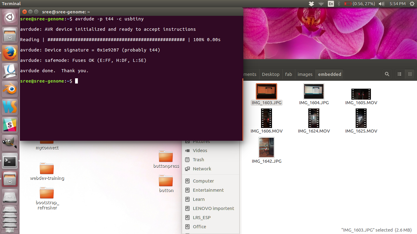
avrdude check success
If you get error try connecting the ISP properly and try again. Remember the -p and -c values here are specific to my device. If you are using another programmer and board, do change them before use. To find the short names of the board and ISP run "avr-gcc --target-help". Now you are ready to program your board.
d2. The LED Blink Program( Digital output)
-
Using your favorite text editor, write the program. This is the program i used. After writing it,
save it as "blinkLED.c"
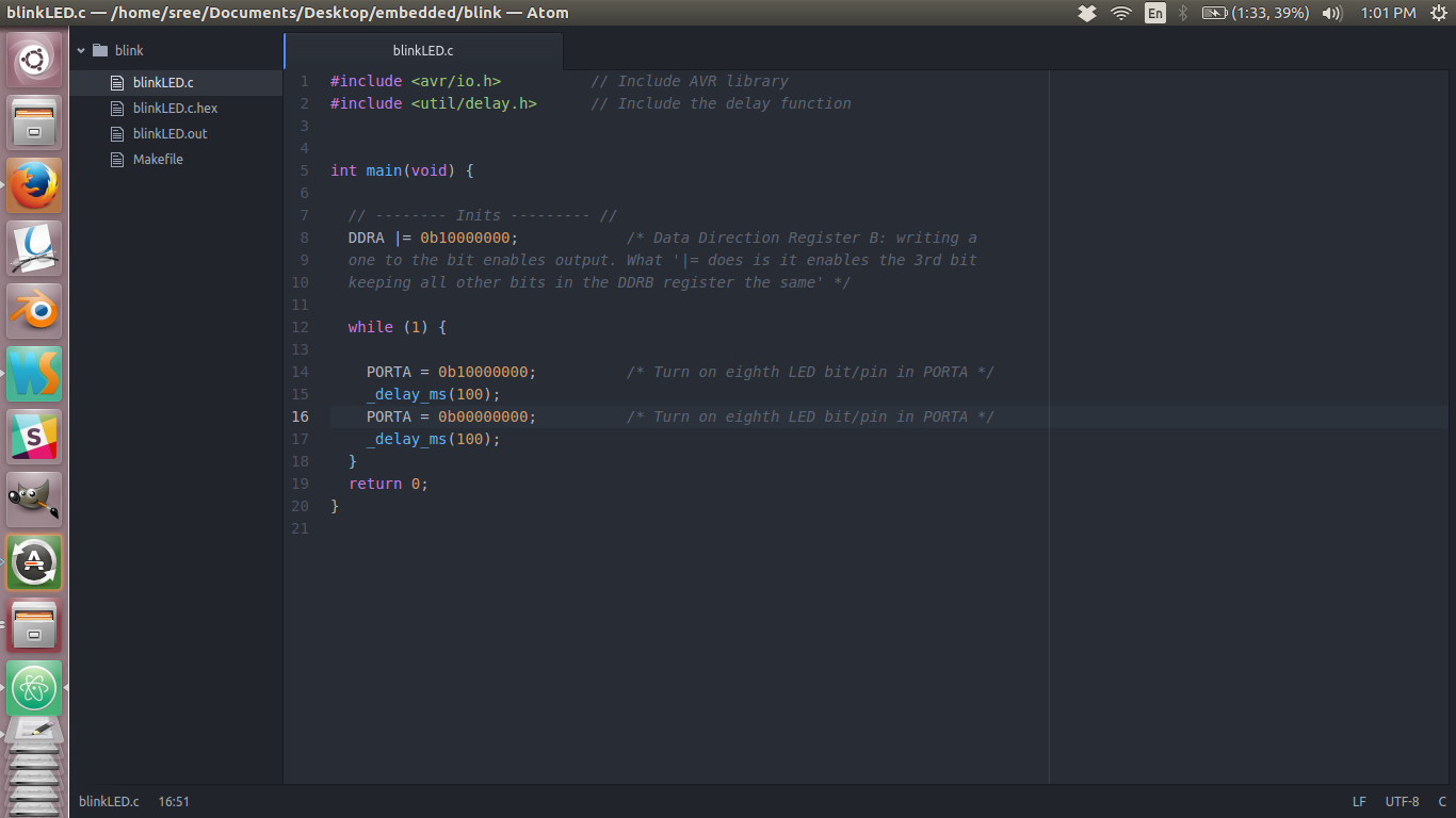
Led blinking program
-
Copy the make file from the following link and make changes if necessory
Make files help configuring and building c files with ease. I am using the make file from Neil's example . You can see that there are few variables being defined on the top. Edit the first line to "PROJECT=blinkLED". This will configure the make to build the blinkLED.c program. If you are not using attiny make sure to change this on the make file. For a complete list of supported chips, type "avr-gcc -- target-help" and about halfway down you’ll find a list of “Known MCU names.”
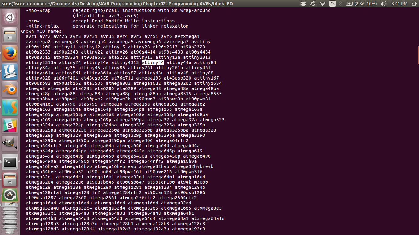
list of names for MC
Also Make sure to name the make file as "MakeFile" without any extension. This will make sure that you can simply call "make {commmand}" to run a routine such are flashing. If the file name is different you will have to use "make -f {filename} {command}". - Now run the make file by typing the following in the terminal.
make program-usbtiny
This command will generate the .hex files which get uploaded into the MC. IF everything works fine You will see the LED blinking.
Output of first program: blinking LED
The c file
The make file
Make files are just helping you easily compile and build the programs. You can even use make files available with any of Neils code to do the same. But make sure to set the CPU speed and MC type right or else you will get an error. Also the command for flashing is different. If you open up his make file you will find commands and the actual commands executed. So makefiles are like creating shortcuts for bigger commands. It also makes linking and other configurations easy.
Understanding the code
- First we include the libraries using the #include statement. For default libraries, ie those in the system include directory (usr/include) we use the angle brackets and for libraries we define(in the current directory) we use the double inverted comas.
- Next we define the main loop in which all the code get executed.
- Then we have the port initialization. As explained earlier we have Registers to be used to configure the ports as input or output. Here we are using the "A" port and using the 8th pin (PIN7) of the port as output. We can see the bitwise operators used in assigning the port. Refer this for more info. Understanding these operations are a key to AVR programming so take time to master them.
- Then we have a never ending loop using while. Inside this we enable the 8th pin in PORTA for 100 milli seconds and then disable for 100 ms thus getting a blinking effect.
e. Making a breakout board for learning AVR programming
The board build on the design week is all soldered up and has a limited potential in exploring the possibilities AVR has to offer. For further explorations with AVR i make a new breakout board. This board has all MC (almost all) pins connected to headers so that they can be connected over jumbers to introduce any periferal as we want. The ISP pins except the reset are reused. The resonator in the circuit can be optionally introduced with a couple connectors so that the board can be run with and without a resonator for learning purposes. The details are given below.
t.brdThis is the schematics i made out of eagle. Here i am using the Attiny 44 as the MC.
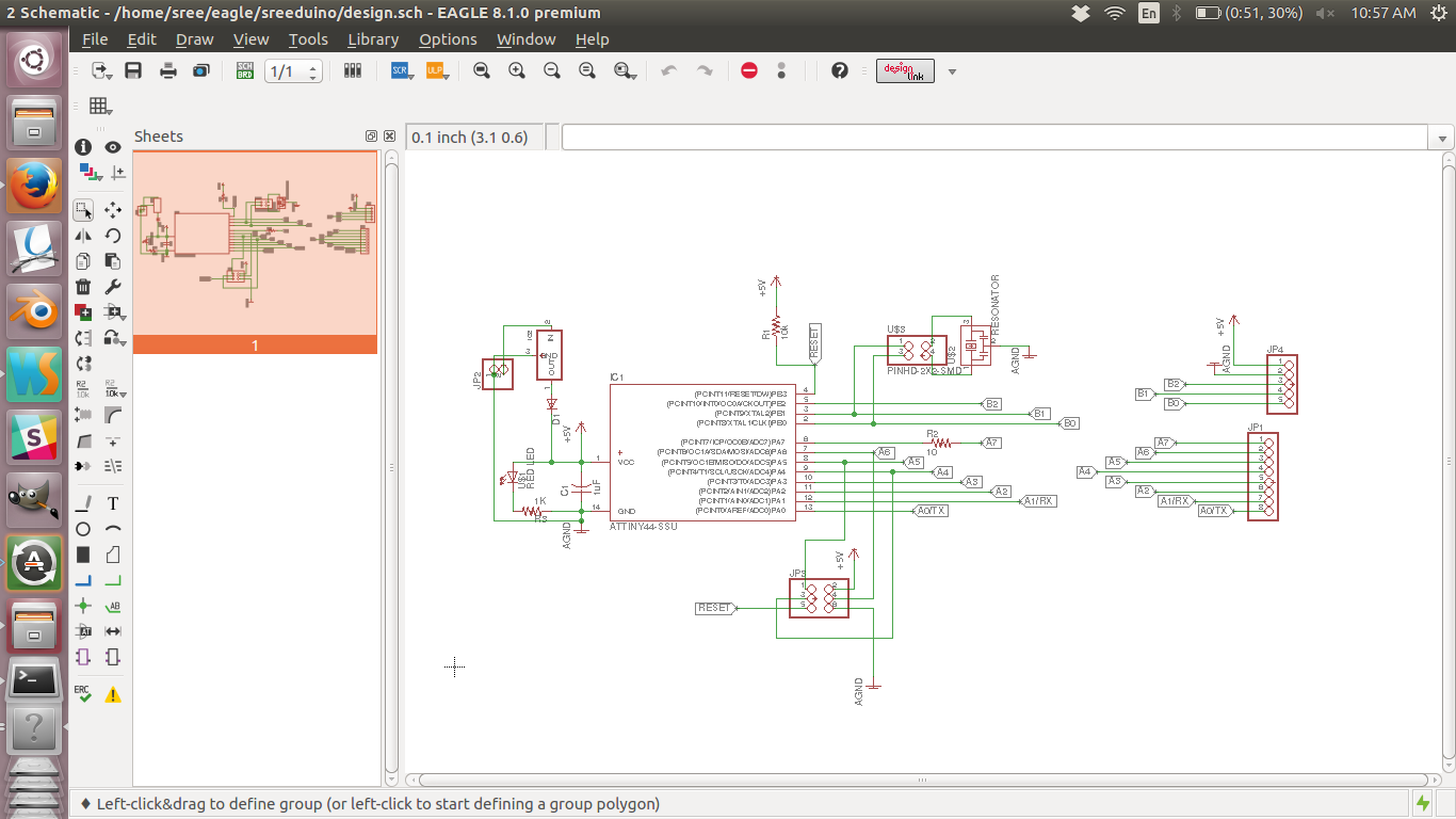
Board schematics
Now i made a board layout with manual routing.
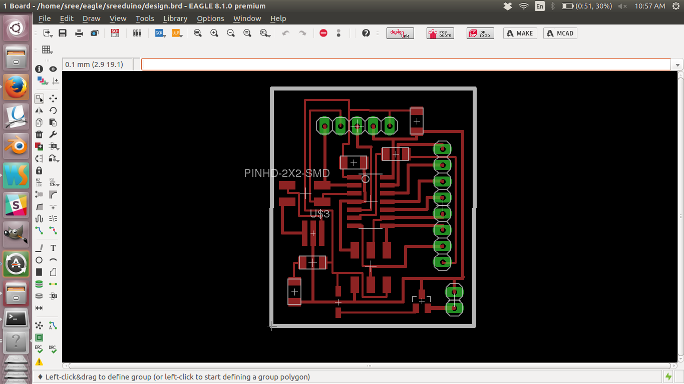
Board layout.
Original scnematics file
Original board layout file
Later i made the board using the modella milling machine and soldered all the components.
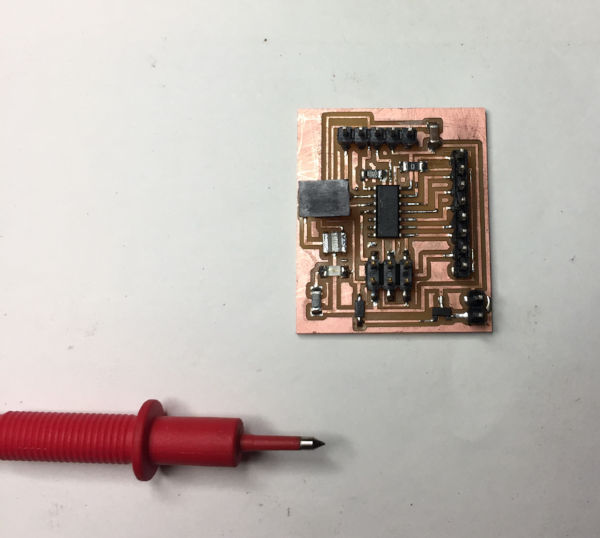
Final Circuit board
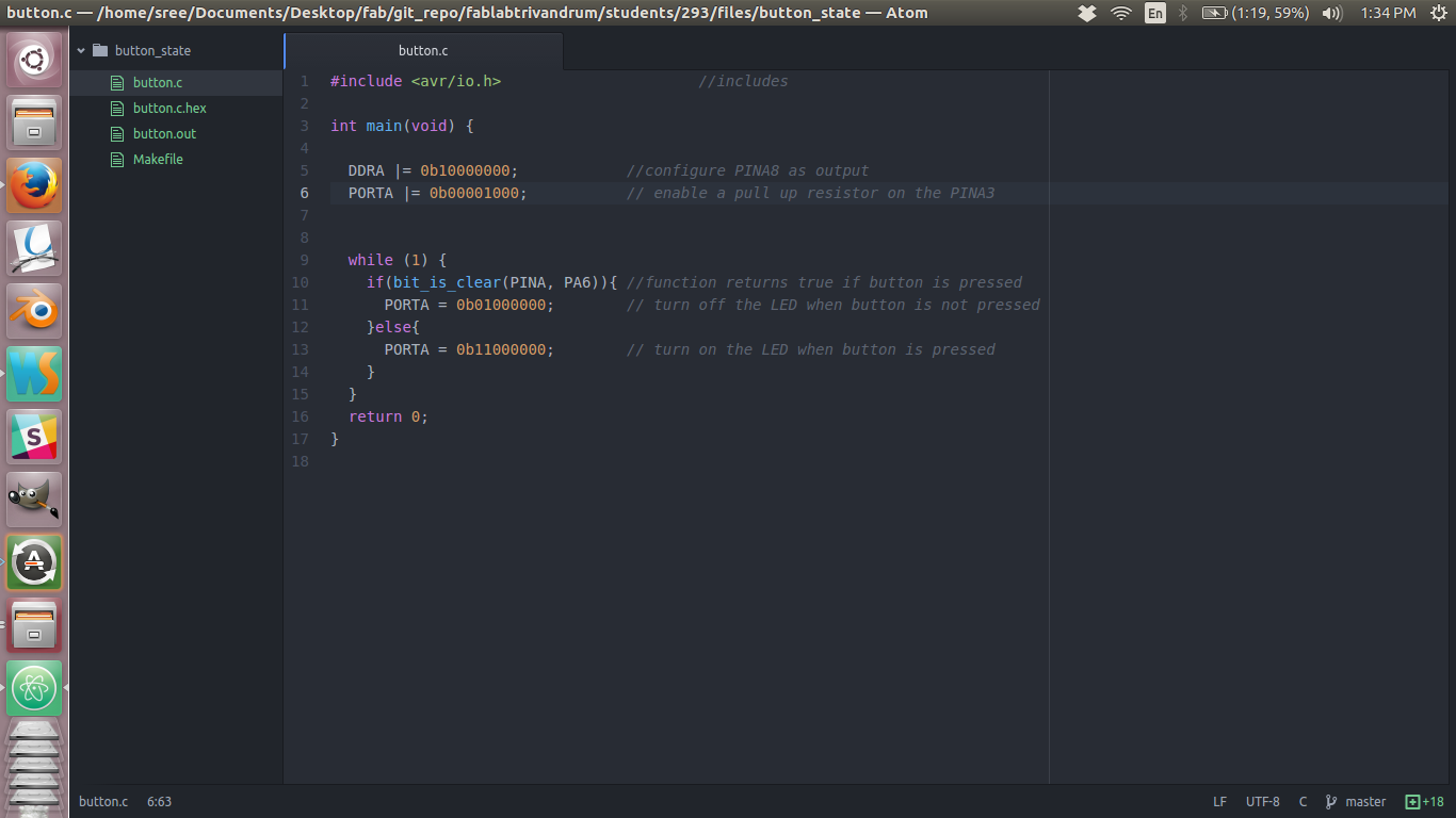
e1. The Switch Program (Digital input, On Attiny44 breakout board)
LED toggling on button press
Here is the code
Button program code
The c file
The make file
Understanding the code
- Most of the code are as our previous example. The main defence is that we are enabling a pull up resistor on PINA3. See that when the PORT is in input mode if we enable the purticular pin, then it will be pulled high (binary 1).
- We also use a function to check if the button is pressed or not. "bit_is_clear" return true if the pin state is low(button pressed) and false other wise. Thus the LED lights on pressing the button otherwise it is in OFF state.
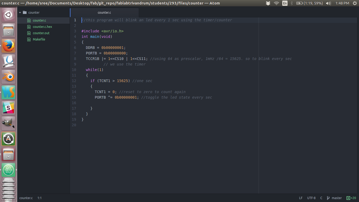
e2. The Timer/Counter Program (On Atmega16A-PU on breadboard)
This program is run on an ATMEGA16A-PU and the connections where made on the breadboard. Link to tutorial
i followed.
LED toggling on every second
Here is the code.
Timer/Counter program
The c file
The make file
Understanding the code
- Here we use the Timer/Counter Control Register (TCCR1B) which is a 16 bit counter with a prescalar of 64 giving 15625 counts equals one second.
- In the while loop we toggle the state of an LED once the counter had reached 15625, ie one second.
e3. Interrupts Program (On Atmega16A-PU on breadboard)
This program is run on an ATMEGA16A-PU and the connections where made on the breadboard. Link to tutorial
i followed.
This is the code.
The c file
The make file
Understanding the code
- On line 8 we are enabling the global interrupt with the function call.
- Then we turn on the timer and use prescalar of 64 as in the earlier program.
- LIne 14: we enable an output compare registor and sets the count for one sec to be 15625. Thus when the counter reaches 15625 a timer compare interrupt is fired. This interrupt is handled in line 21. We simple toggle the state of our LED on this interrupt.
e4. Making some noice with AVR
Music with AVR (On Attiny44 breakout board)
This is the code.
The c file
The make file
Understanding the code
- Here i am using the delay duration to make a music with the speaker.
- The speaker has very low resistance so we cannot connect it directly to our output. I use a 10 uF capasitor in series with it to limit current.
e5. Making a Piano with AVR
The AVR piano (On Attiny44 breakout board)
This is the code.
The c file
The make file
Understanding the code
- Here i am using the delay duration to make a music with the speaker. Each tune is enabled with a button press.
f. Programming with arduino
f1. Blinking the LED
Lets start of with the hello world program, ie the blink led program.
f2. Tools required
- Fab ISP; build in week 4
- Echo board; build in week 6
- ISP cable; from week 4
- Laptop; i Use ubundu
- Arduino IDE (software only)
f3. Step By Step
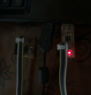
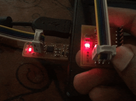
- I connected the FabISP which i made in the electronics production week to the echo
board varient made in the electronics design week. now this assembly was connected to the
pc as in the photo below.
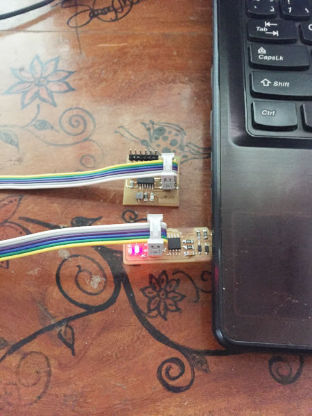
Connected boards
The red led in the ISP started to glow indicating that it is working properly. -
Next i downloaded the Arduino IDE from their website
and installed it.
Now i opened the example program which comes shipped with the IDE. The LED blinking example code was
opened. From reading the
datasheet of ATTiny and looking at my design on the board i could find that the LED is on the pin
number 7. So i edited
the code and click compile and clicked upload again. Now i got an error as follows.
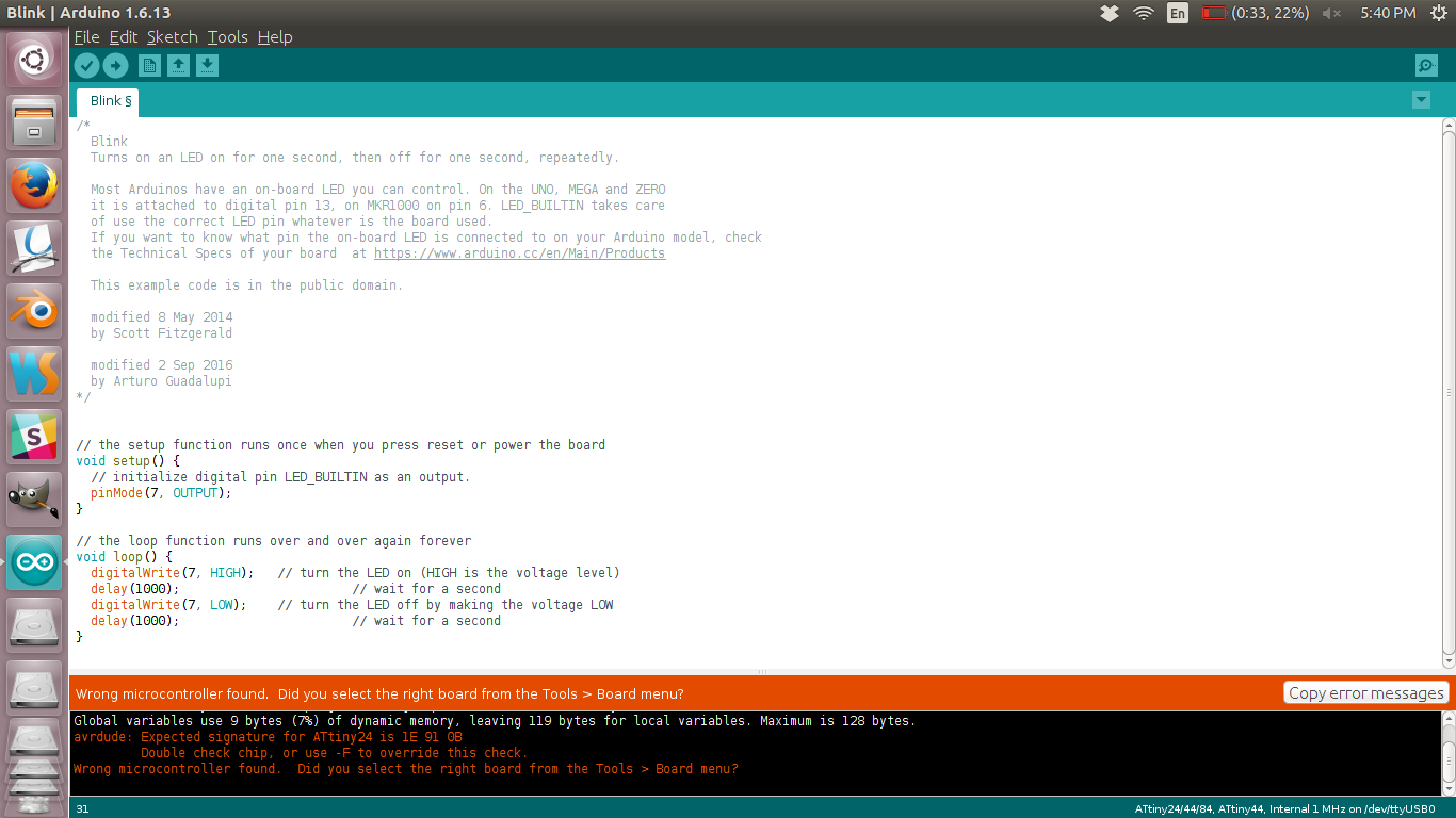
Error
- The error message was quite informative and i checked that Tools>> board menu.
I could find that the option was not ATTiny, which was active. I searched the dropdown for attiny
and was
unable to
find it in the list. I started searching and could find that Attiny doesnot come here by default and
we
need to
include it manually. This link referenced by
Yogi
Kulkarni
helped me add ATtiny to the list.
I gave the link for the json files and clicked okey and i could find ATTily in my list. Other
configuraiotions where also set in accodance with the
Attiny i am using. The image below shows the settings i used.
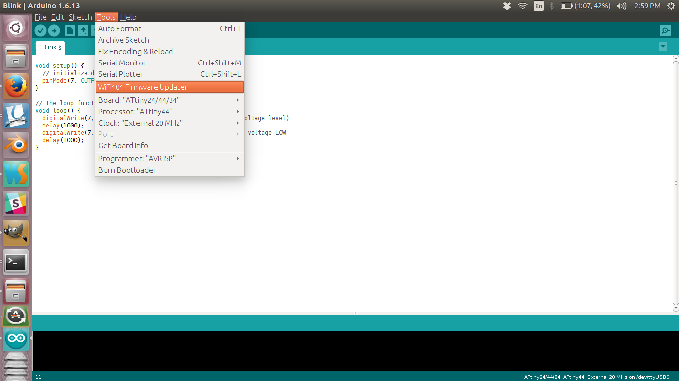
Settings
You can see the Board set to ATtiny24/44/84,the processor to ATtiny44, clock to Internal 20 MHz external also the Programmer to USBTinyISP. This means that we are using USBTinyISP as our programmer to program a board with ATtiny44 with external 20 MHz clock
- I uploaded the sketch again and the LED started to blink.
Blinking LED
The sketch file
-
I also experimented with different blink speeds. Now i wanted to try multiple LED blinking togather
but here in the board as it is already soldered i dont have an option to do that directly. So i took
my arduino and connected the LEDs and programmed it to get 5 LED blinking simultaniously.
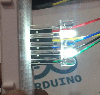
Blinking Multiple LED
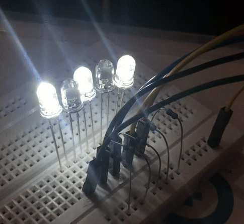
Fast blinking LED
The sketch file
f4. Using the button the button
-
Next thing i want to try is to light up the led on button click. I went throught Tutorial
points tutorial to refresh on my
skills on arduino. Refreshed the concept of Pull up and pull down resistors and
created the sketch for the button activated LED
program. This is the result.
Button activated LED
The sketch file
g. Summary
- Learned to program micro-controller with c and arduino.
- Tried most of the features in a microcontroller such as timer/counter interrupt, pwm etc
- Made an attiny breakout board to learn programming
- After trying to program in both c and in arduino i understood that arduino is useful when you dont want to dig deeper into the hardware aspects and need quick results. But is not very flexible when it comes to complex tasks and extreme flexibility. The code size is very large when using the arduino due to all the libraries. Whereas C is little bit difficult to learn but offers good flexibility and power to the user. I am planning to continue with C as i liked its flexibility.

This work is licensed under a Creative Commons Attribution-NonCommercial-ShareAlike 4.0 International License.