3. Computer-Controlled Cutting
Index
- Assignment
- Vinyl Cutter
- Few things i made with vinyl cutter
- Pitfalls
- Laser Cutting
- Step by step into how to use the laser cutter
- Pitfalls
- Group assignment for the week
- What is kerf
- How to find kerf
- Assignment for the week
- Showcasing the pressfit kit
- Problems faced and their solution
- Safety tips
- Summary
A. Assignment
- Make lasercutter test part(s), varying slot dimensions using parametric functions, testing your laser kerf & cutting settings (group project).
- Cut something on the vinylcutter.
- Design, make, and document a parametric press-fit construction kit, accounting for the lasercutter kerf, which can be assembled in multiple ways .
Machines where introduced this week. The machines we used this week where
- vinyl cutter
- laser cutter
B. Vinyl Cutter
My first encounter with a vinyl cutter was a couple of years ago when i made the
number plate for my bike.
The guy at the shop was printing the number on a plastic kind of sheet and i found that after the so
called printing the letters where
cut off leaving holes in there place. This sheet was used as a stencil to paint the numbers to the
number plate.
Now i find the same machine here. The model we have is Roland CAMM-1Servo.
After our instructor Yadhu gave us a demo i got really curious about how precise the
blade cut the sheets, just the top layer leaving the bottom layer intact.
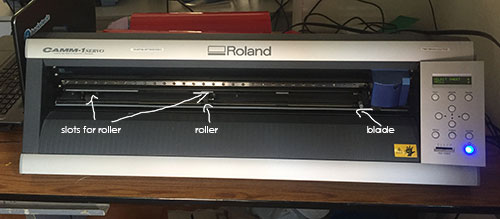
Vinyl Cutter with its parts
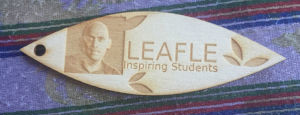
For vinyl cutting i had choose what to cut. First i picked a photo of myself to create
a sticker.
The major constrain in printing some thing like a photo is that you need to convert is
properly to a binary image(black and white only).
I used photoshop for the purpose. First i converted the image to a grayscale image and then used the
treshold function in photoshop to adjust the values of white and
black. I had to later do a bit of cleaning up to get an image as follows
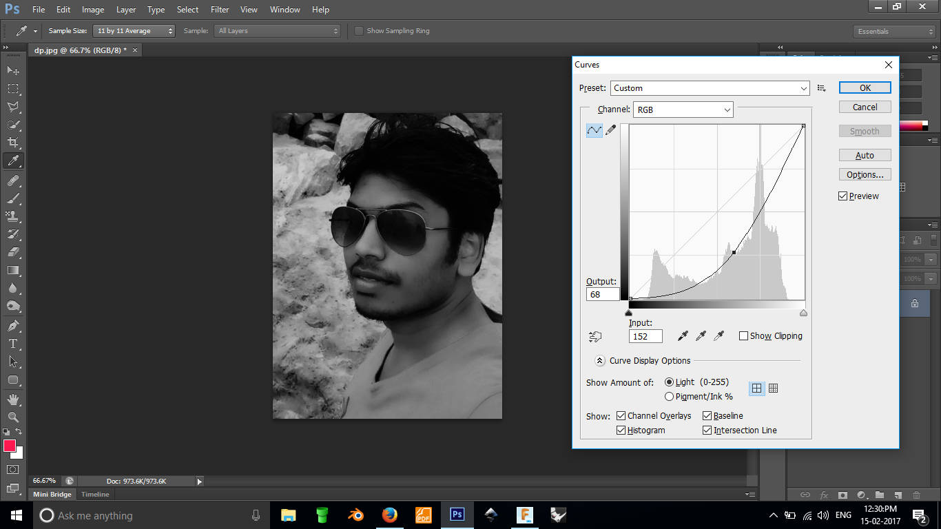
Convert the image into grayscale
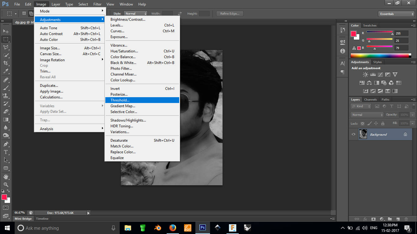
Tresholding the image
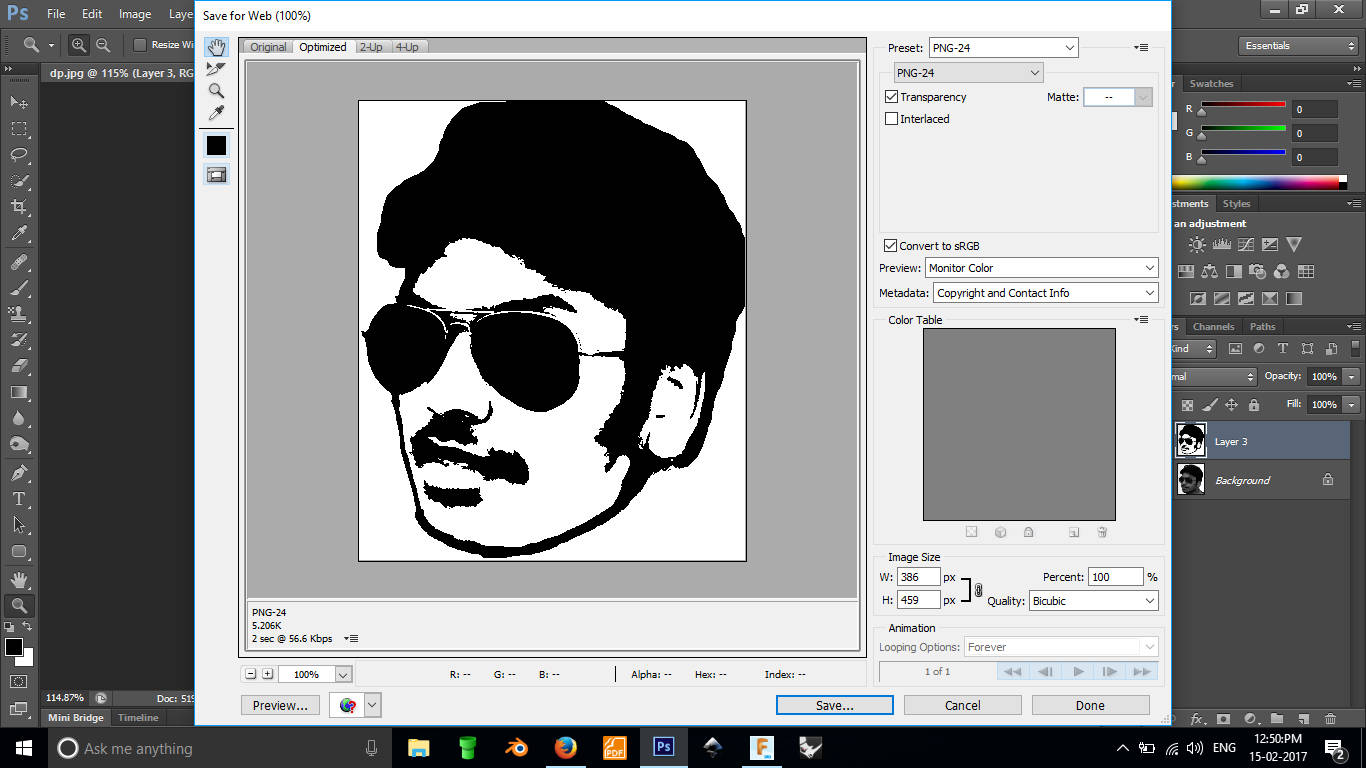
Saving as png
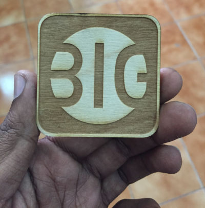
Later i used the same process to make a sticker of the logo of our company.
This machine needs a .camm file as input. The FAB team has a large set of tools to
convert images in different format to .camm.
This is called as a FAB MODULE. The program can be launched by running "fab" in the terminal. It is a
simple program which can first let you choose the input and output
file types.Next we can resize the image if needed and then you can vizualize the path; here we can fine
tune the
settings such are error pixel or power. Remember not to set the error pixel value to
very small values, if so the cutting will be worn out
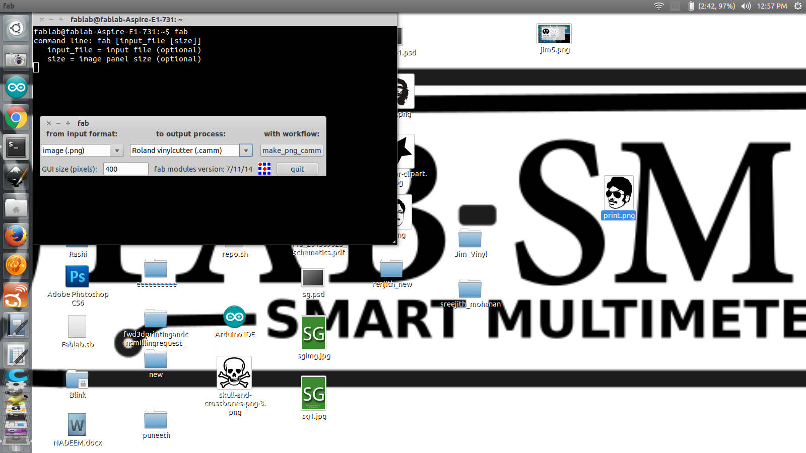
Launching the fab module
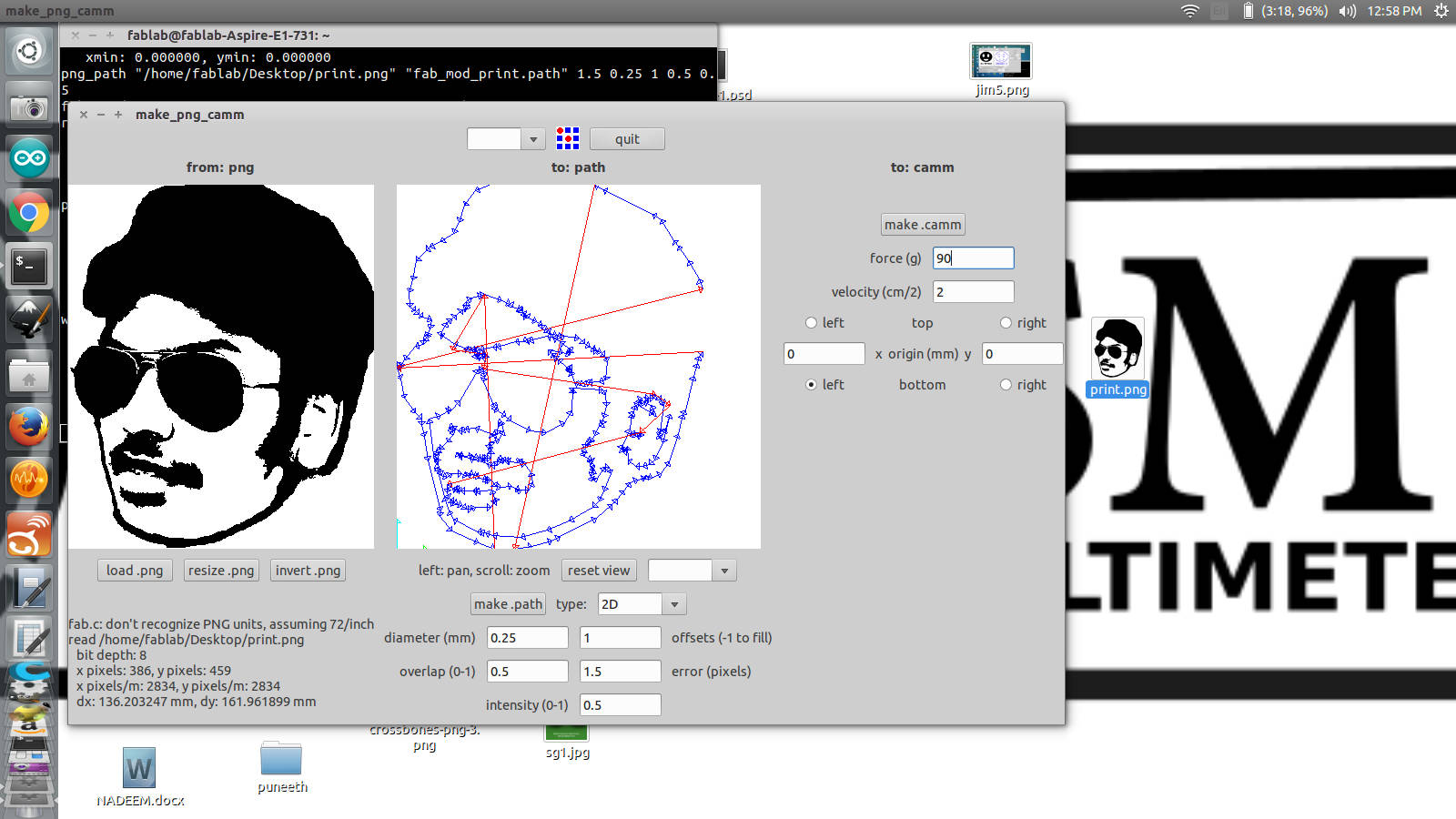
Resizing, fine tuning
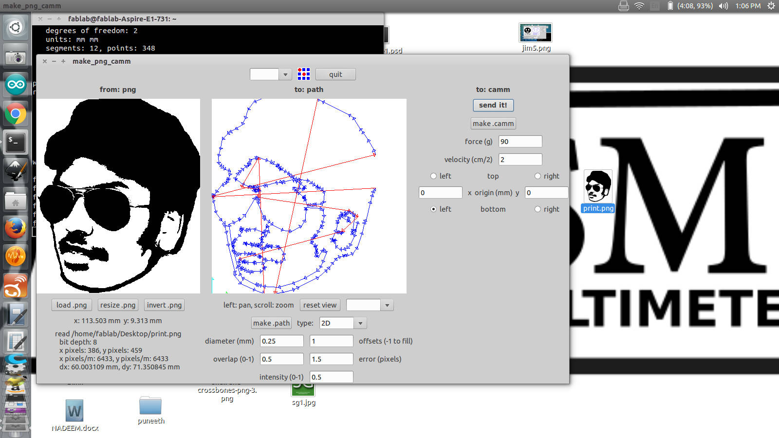
Generate and send the .camm file
In the machine there are just a few controls and adjustments. The primary thing is to load the sheet.
Sheets can be either a piece of a roll. There are wheels which pull the sheet in while cutting. The
placement of
these rollers are restricted to certain regions marked with white. Take care to always place the wheels
on these places.
If you are using a piece, then the machine measures the length of the piece before you cut. There is a
sensor in the
machine which lets it do that. So while using piece make sure that you place it above the sensor also so
that the
machine can measure it.
Once you have properly loaded the sheet you need to choose the type( piece or
roll) from the machine hard
control
after which you can place the blade where you want to start cutting and click and hold the origin button
to save the
position. With that done you can send in the file from the fab modules and get it done.
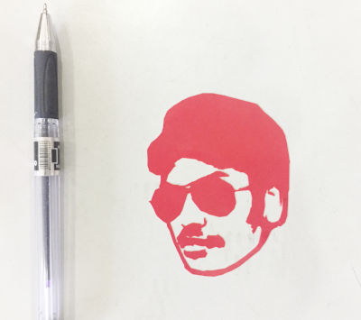
Final sticker sticked on to a table
Original file
b1. Few things i made with vinyl cutter.
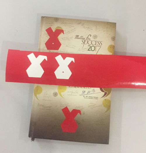
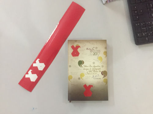
Original file of logo
b2. Pitfalls
Once in between someone else was using the machine and his cutting has already started. I opened up another file in the fab modules and suddenly the printing was haulted. So we realized that even after sending the .camm files we cant load another work in the fab module, we need to wait till the cutting is complete.
C. Laser Cutting
Lasers always fascinated me; the technology, the applications and the way it has
chained the things around us.
Few links about laser tech
laser tech
explained
video explanation
With laser cutting i was exploring more uses of laser. Our machine is Trotec Speedy
100. Our instructor Vishnu thaught me how to use
inkscape designed files in the laser cutter. He showed me some demo of cutting and engraving. I was
inpressed the way the machine engraves fine details into
craft wood.
c1. The laser cutter machine
The machine we are having in our lab is 'Tortac Speedy 100'. It has a bed size of 610 x 305 mm
and a height of 170 mm. It works at 12 -60 watts power depending on the settings. This machine does not have
auto focus and we have to manually set the focus.

Laser cutter,Speedy100
c2. machine control and workflow
- First when we turn on the machine, the bed moves down to zero and the control is handed over to the user of the machine.
- At this point we can load the material to be cut. Place the material in such a way that it is aligned to the base plate with honeycomb structure. Make sure that the material is evenly placed, use cellotapes if necessary
- Now use the laser head move controls to move the head somewhere to the middle of the material
- Place the apparatus to find the focus on the laser head, make sure that it is hanging and can move freely.
- Using the bed control slowly rise the bed till the point where the material in the bed touches the focusing apparatus and it falls down. Thus the focus is set.
- Now again using the controls, move the laser head to the origin point where you want the cutting to start from. This point will be the top- left of the shape. Cutting happens to right-down direction from this point
- With that you are done with setting up the machine. The speed, laser power, and freequency of the laser can be controlled from the software. The simplicity of this model of laser cutter is that it connects to the pc as a normal printer. From the designing software click print and choose the speedy100 as the target printer. In the settings select the print dimensions. WE usually give 2 mm padding on both axis. Ie if the cut size id 50x50 we give 52x52.
- The machine takes only vector files, so that means you can only print a vector shape. The machine has setting in which we can choose the color and corresponding function. The default is red to cut and black to engrave. We can add more or edit existing. The power of both can be specified by the user. It is ofter a good practice to find the right settings for the material on first use and save it within the interface
- Now once you have the design file first thing to do is to change the color of cut parts to red and engraveable parts to black in the design. Also make sure that the cut line thickness is around .01 mm. With all that set simply click ctrl +p and choose the laser cutter from available printers. Set the dimensions and choose the material from the list(already saved). If you are cutting acrylic 3mm see if there is a settings already saved for it, if not create one by trail and error. Once you are done with all that you can click print. The control will be passed over to job control software.
- In the job control software you can see the current job we just posted.
- Click on the connect button on the bottom left with an icon of usb to connect with the cutter. Once after connection is made a cross appears on the region showing the base. this cross represents the laser head position.
- Now drag and drop the job from the side panel into the cutting region on the software. Place it close to the cross and you can see the job getting snapped to the cross. Place it there
- Now simply press the play button, the cutting will start. If you are having a filter attached to the cutter make sure to ON that before starting the cutting operation.
- Later to remove or reset the job right click on the job to get a pop up with all the possible options.
c3. Step by step into how to use the laser cutter
-
1. Making the design
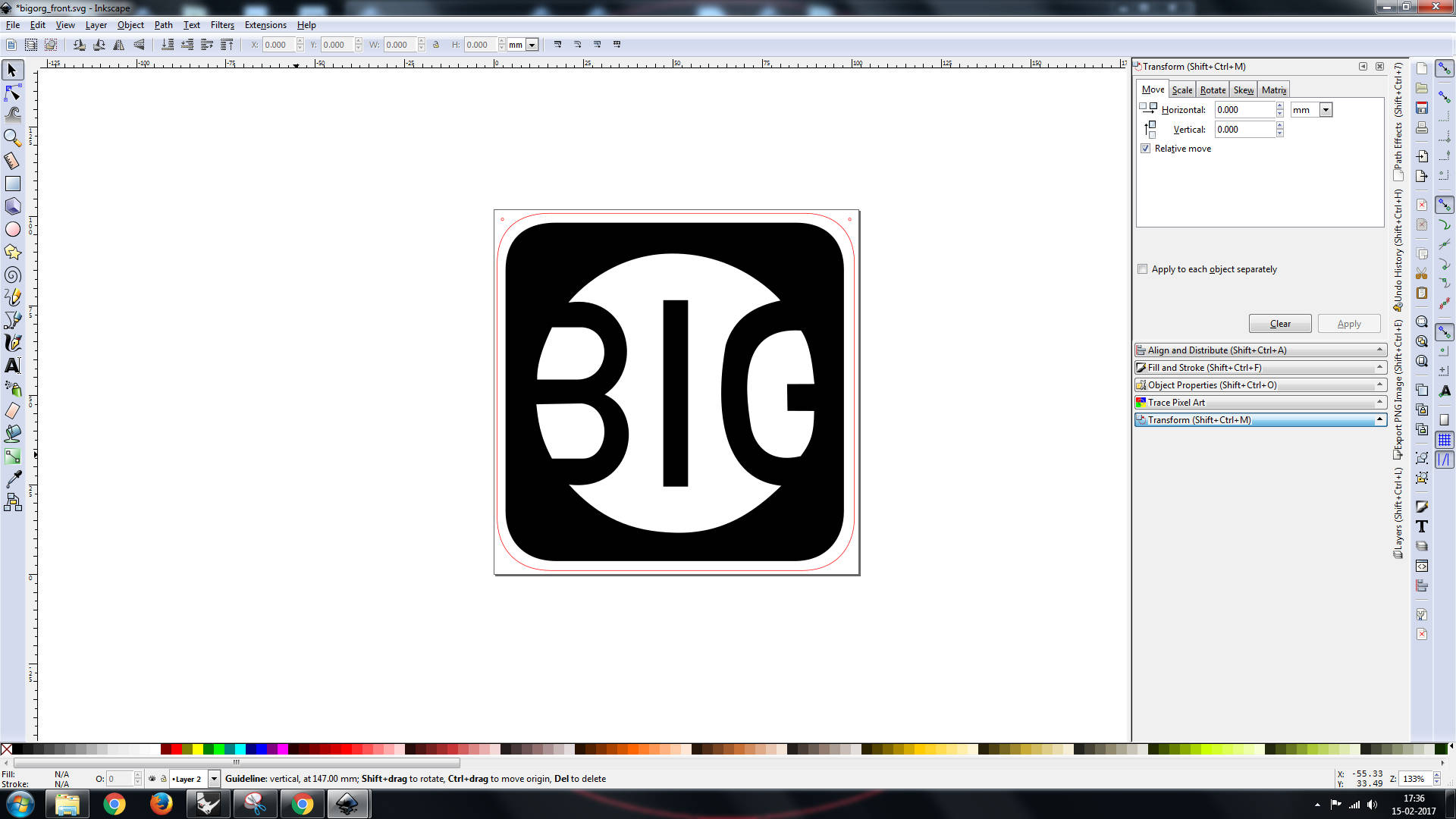
First you need to make the design using any vector software, i Used inkscape for this. While designing all the parts you need to make sure that the cut must be a path and preferably you should give a red stroke of 0.1 mm to the path. The engraving parts can be raster or a vector. The color prefered is black. While designing you need to have a size in mind and do it accordingly which can save you a lot of time later.
-
2. Preparing to print
Before printing make sure that the inkscape is in mm diamentions. Then adjust the document size to fit the design. Now double check that the cutting parts are using rgb(255,0,0) as stroke color. This is because the machine we use cuts with color code. It identifies the red lines to be cutted. If you have a different color it doesnt cut. This is a good point to check if you find that your machine is not cutting as you want it to be.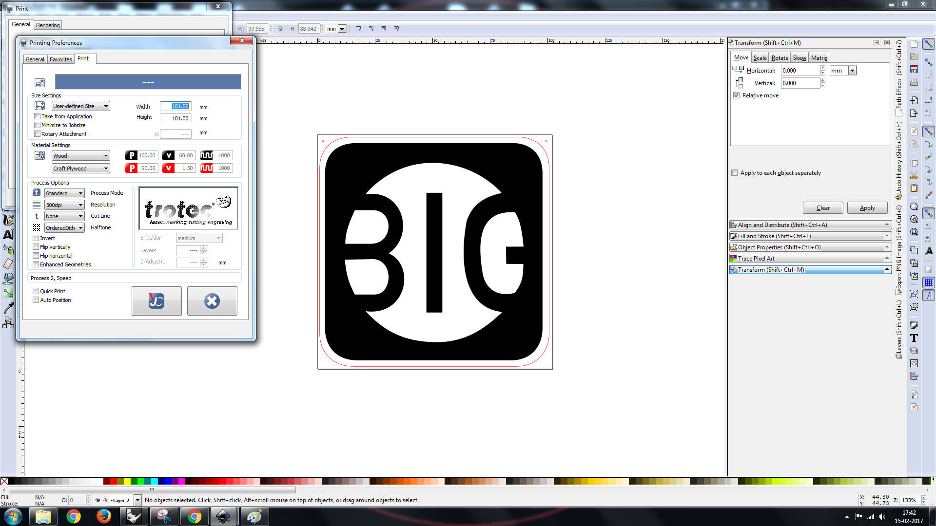
Make sure that you set the diamensions and units correctly -
3. Printing
One you have the colors, diamensions and document size set select file >> print. The normal print menu(as if we are printing on paper) appears and you can see you laser cutter attached as a printer. From the properties icon there you can access the printer properties. Amoung these properties you can choose what material you are using to cut and set the cutting speed, strength etc. After doing all that you can save the settings and click print. On doing so the job will be handed over to the printers job control software. In this software you can see where the laser head is and place our job on that and click print.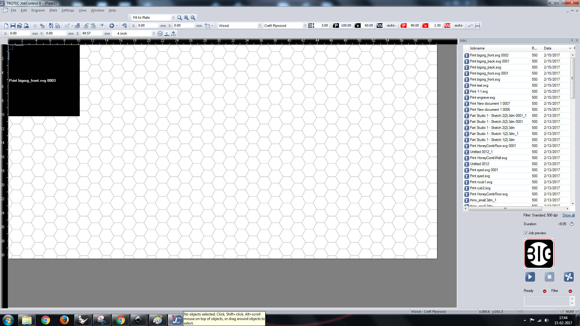
c4. The printed products
C5. Pitfalls
1. Make sure that the document size fits your drawing, you can make the document size
little bit larger that the
drawing size.
2. The document size should all be in mm
3. If in the job control software you find larger sized rectangles than the actual size you expect,
that
probable means you have set the size wrong in the properties session
D. Group assignment for the week
This weeks group assignment was to find the kerf of our laser cutter
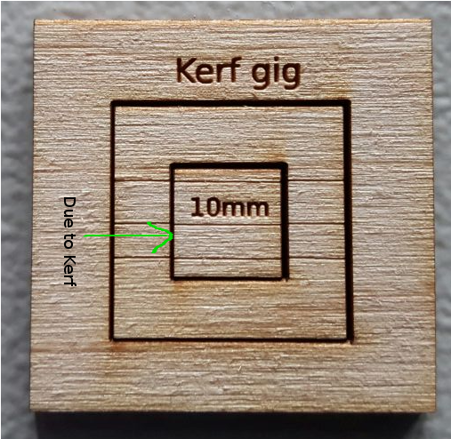
d1. What is Kerf
While cutting with a laser cutter, unlike cutting with a blade due to the thickness of the laser beam, the cut formed had a thickness, this is called as kerf. Kerf depend on the material, and the specificaitons of the laser beam and the focal length of the lens. Finding the kerf is important if you are making a pressfit with a rigid material such as wood or acrylic.
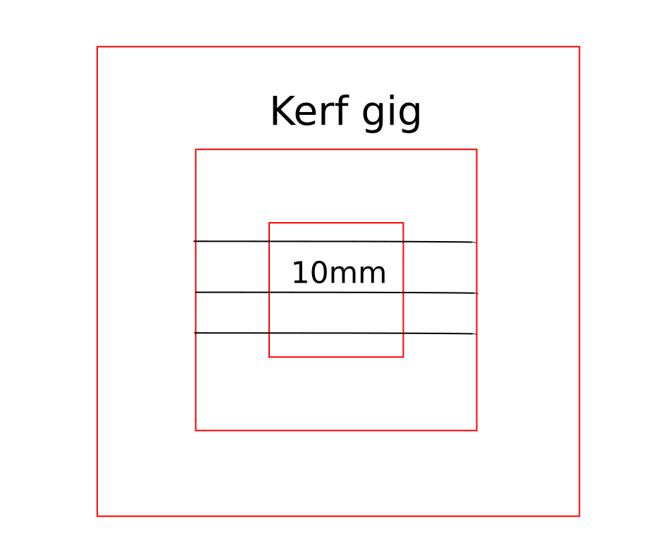
d2. How to find kerf
Finding kerf is simple, You need to cut a small square on the material you want to find the kerf.
With a venier caliper, measure the inner diamension of the hole and the outer diamention of the
piece.
Substract
and divide by two, this is the kerf of the material.
Here we made a kerf gig as shown in the figure below.
Kerg gig
Cut out piece for kerf
photo courtsey: Ajith Kumar
Kerf of the laser printer which was found to be 0.325 for craftwood, 0.24 for acrylic.
E. Assignment for the week
This weeks assignment was to make a press fit kit.
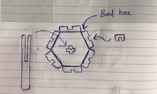
Initial concept
Parametric design
Parametric design is the kind of design pattern in which you make a model based on parameters. The simplest
example is a circle.
You can crate a circle by considering many point in the circle or by defining a function which takes radius
as the
parameter. Parametric design is more like the second way, we define shapes as function with there parameters
acting like controls.
The greatest advantage of parametric modeling is that if you want to bring about some change in the model
you need not recreate the entire
model , instead changing the corresponding parameter is enough and the software automatically updates
everything.
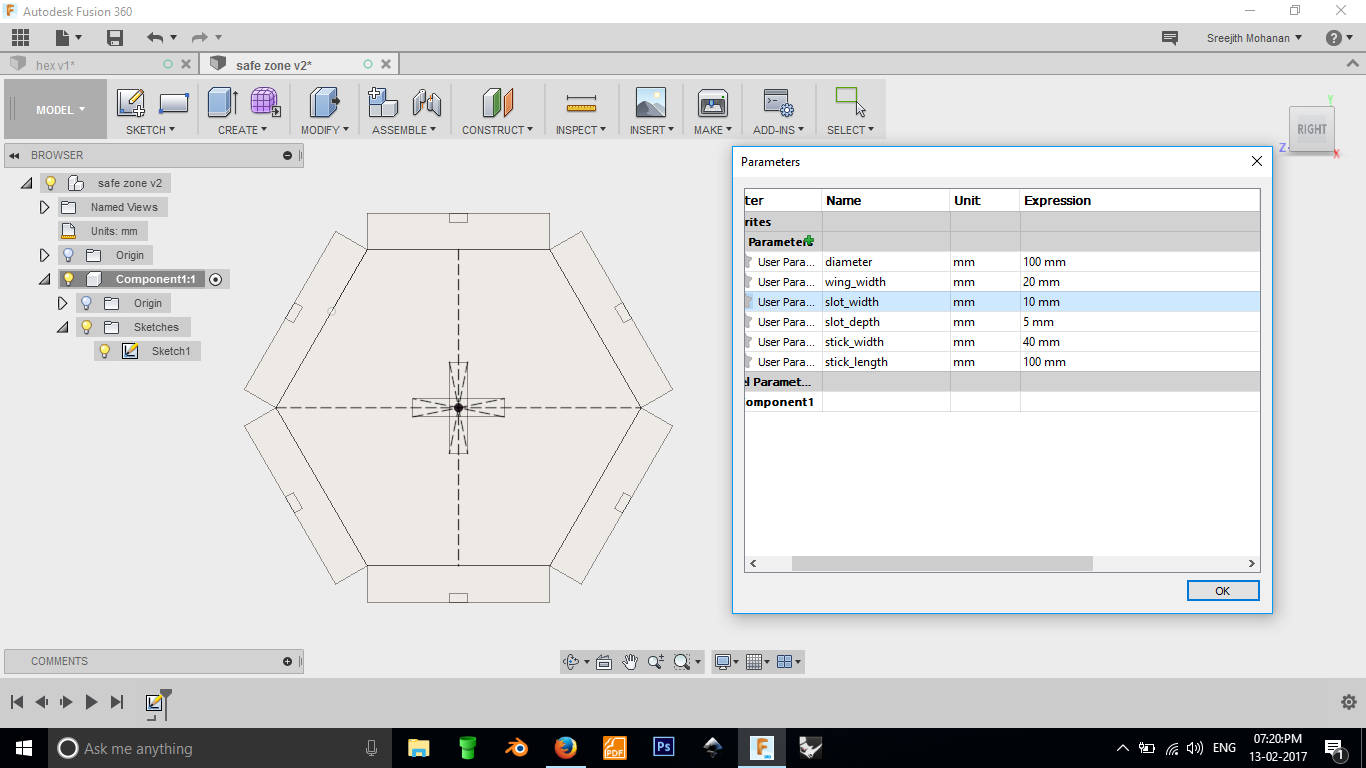
Fussion 360 has a powerful parametric modeling environment. Fussion's model environment is based on sketches
and these sketches are
parametric my default. You can even store these parameter in variables for quick modification. You can
access this menu from
Modify >> Change parameter
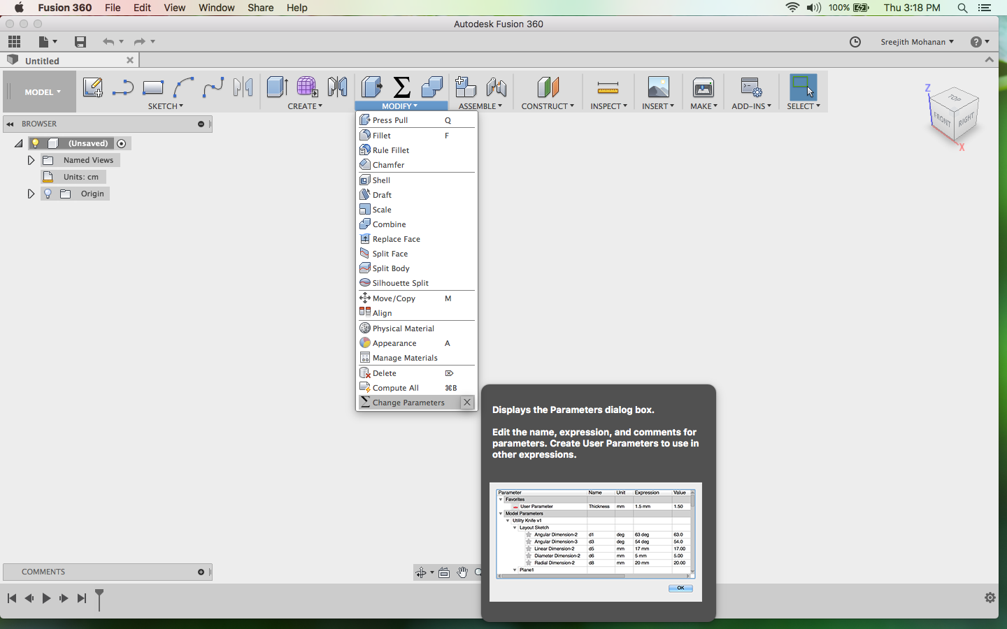
Change parameter section in fussion
Now you can click on the plus button and enter the variable name and the value in the field and save it.
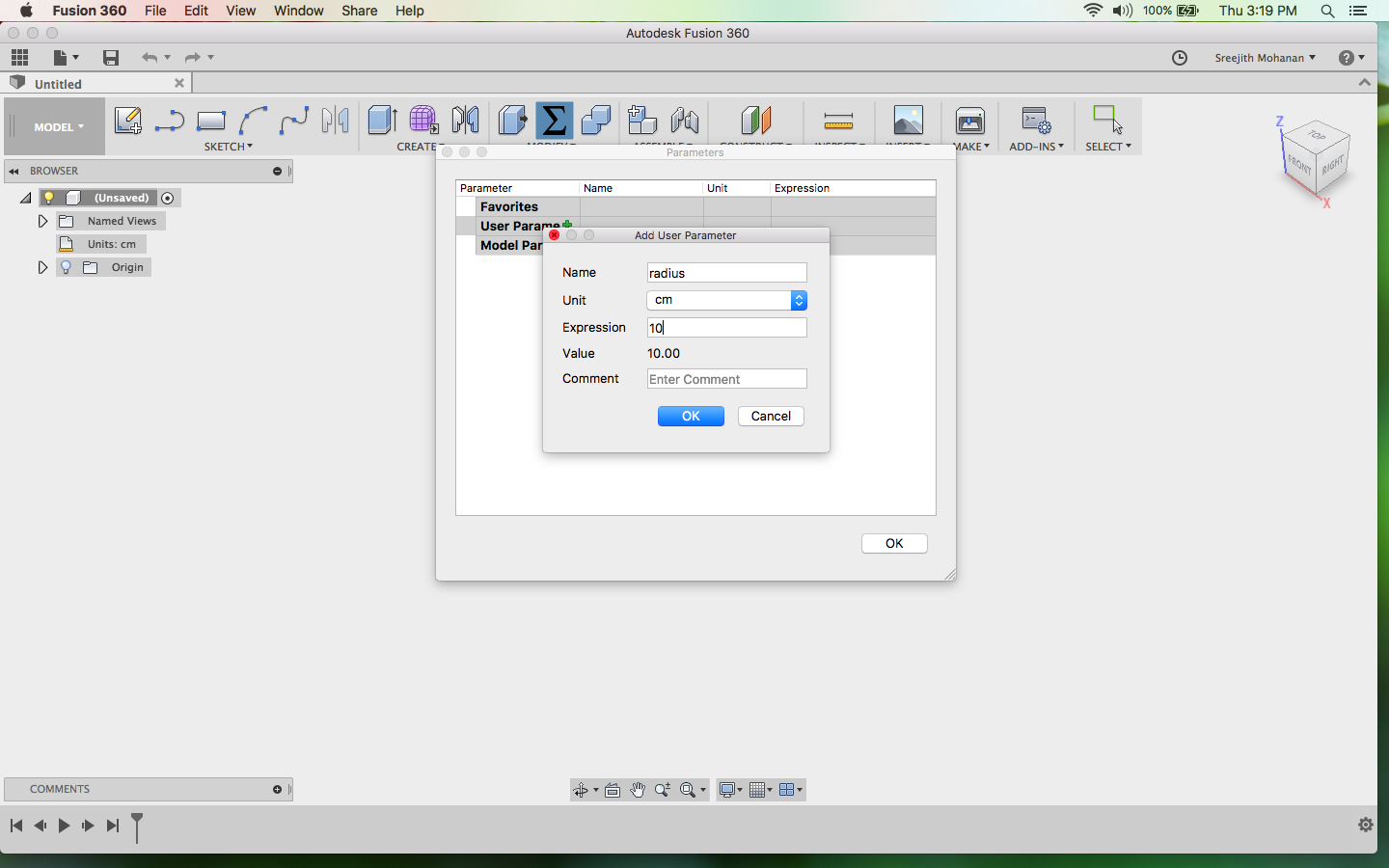
Saving parameters
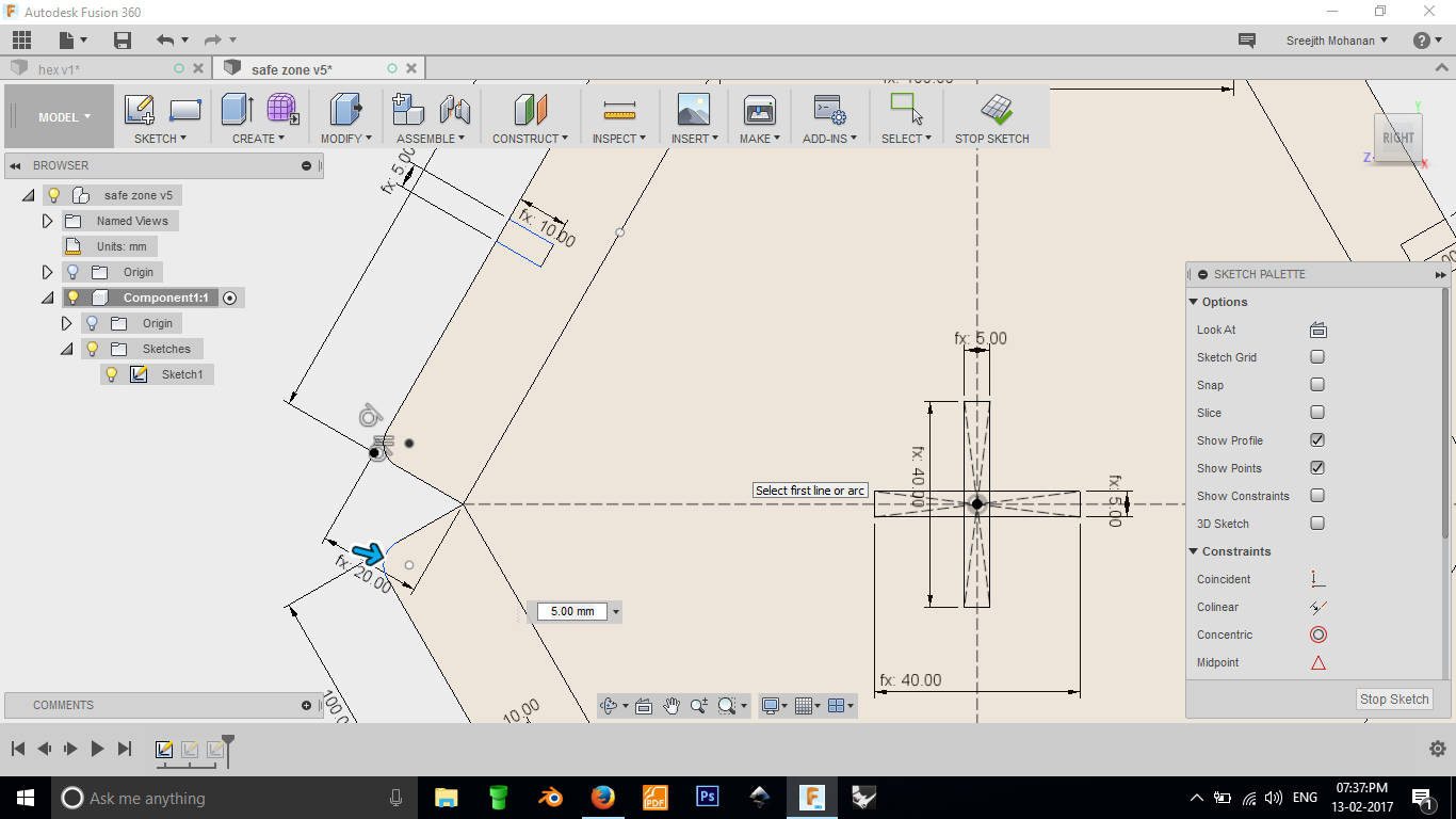
Now while drawing the shape make sure to use this parameter. After making the full design you can change the
value corresponding to any
parameter and the shapes automatically gets updated.
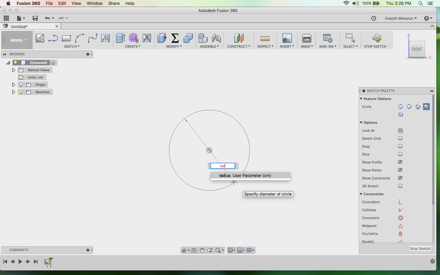
Drawing shapes parametrically
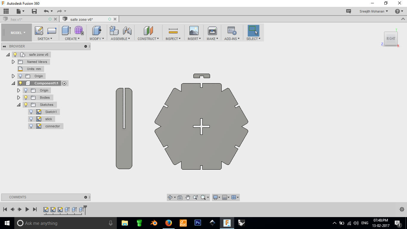
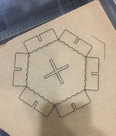
Its time to make the parametric model of my press fit kit. I am making a hexagonal shape with
a connector which can be connected in different ways to form different shapes. I create variable for
dimensions for every part of the shape and
use constrains to make the model parametric. Thus when i change the parameter the whole model get updated
automatically. Here in this model i can change radius, wing length
with fussion automatically updating the design for me. This is show in steps 2, 3,4 and 5.

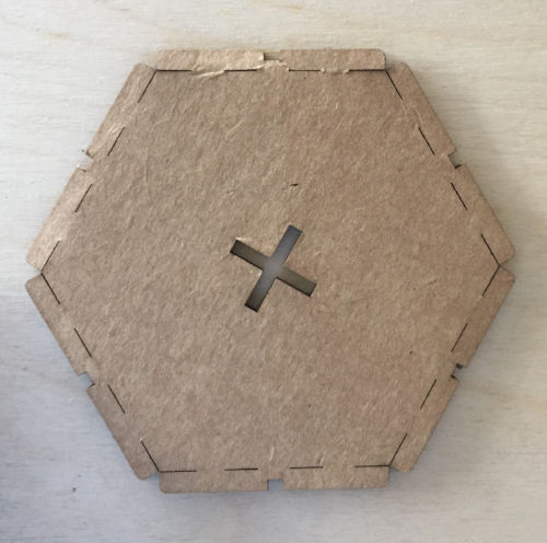
1. Creating the hexagon shape
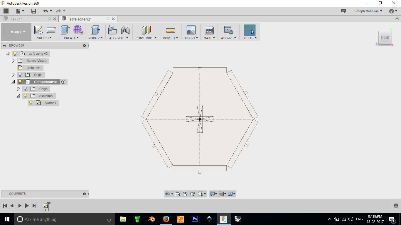
Final hexagon
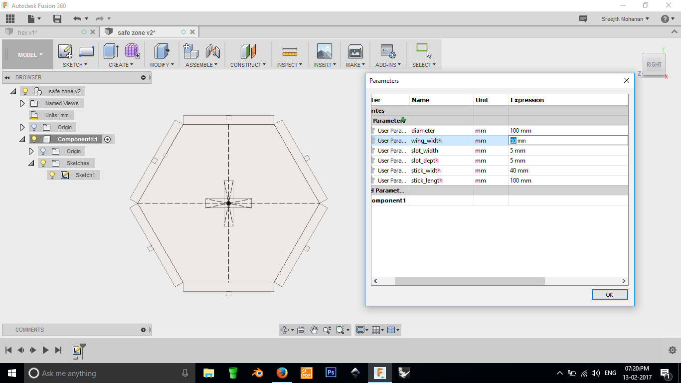
2. Testing the parameters
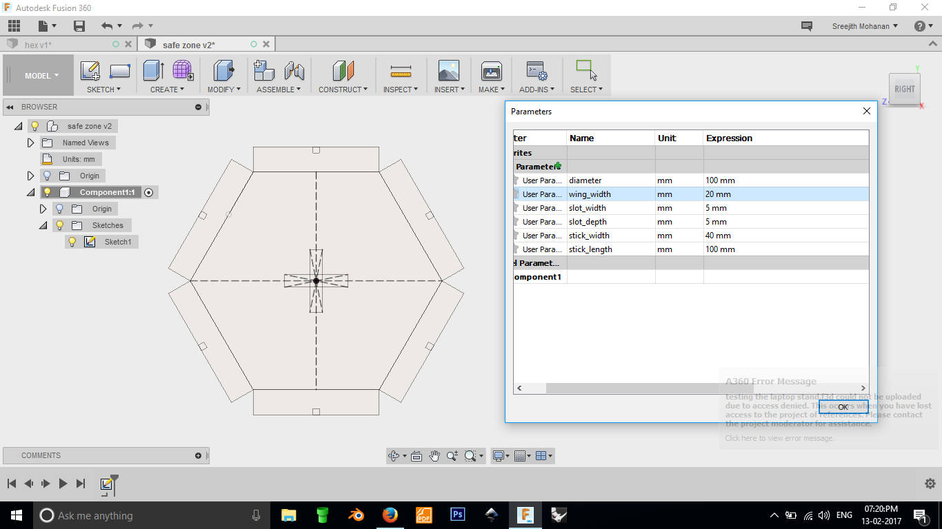
3. Testing the wing width parameter
4. Testing the slot width parameter

5. Testing the slot depth
6. Applying fillets
7. Extruded into 3d model
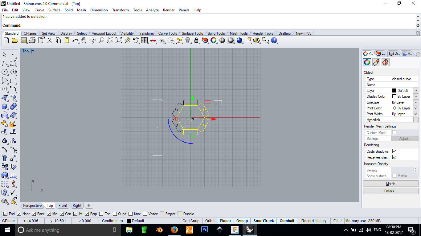
8. Finally exported the sketch as dxf and opened in rhino, cleaned it up and
gave it to print
Original fussion file
Original rhino file
e2. Cutting the parts
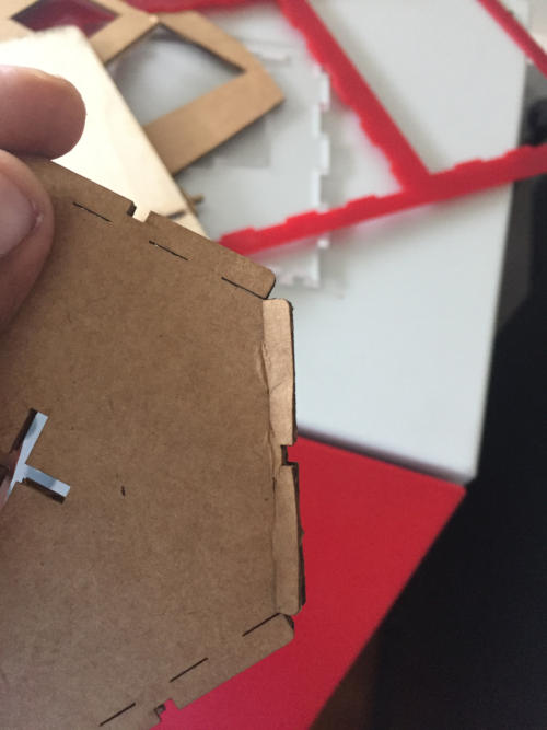
Everything worked well expect that the wings which i
needed to be folded and pinned
was not cut properly. I want the machine to cut everything leaving
the bottom layer of the cardboard so that i can bend it across and clip it. That was a real
challenge to
find the right value of power and speed of the machine engraving.
I cut using different parameters but it was not working.
Testing with bends, here the bend is not forming properly
Testing out different parameters for the bend
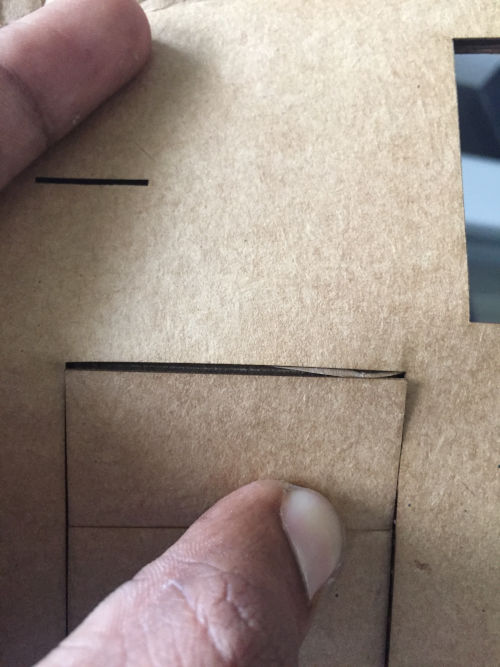
Later Yadhu came up with the idea of double dotted cutting lines and it worked. I have already compensated
for the laser kerf in the design so everything fitted well in the first go.
The double dotted cutting lines
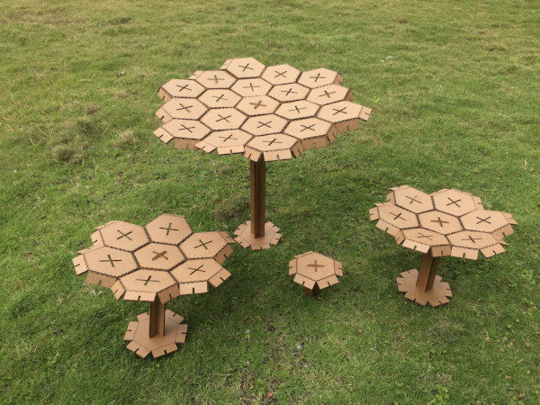
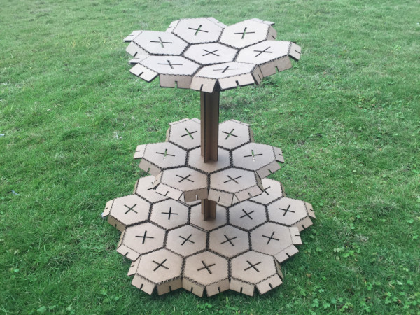
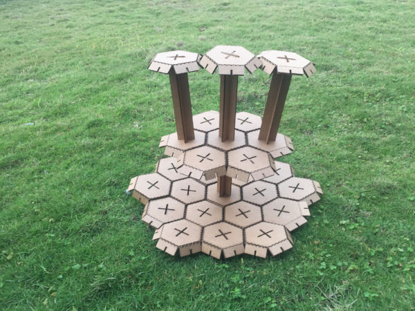
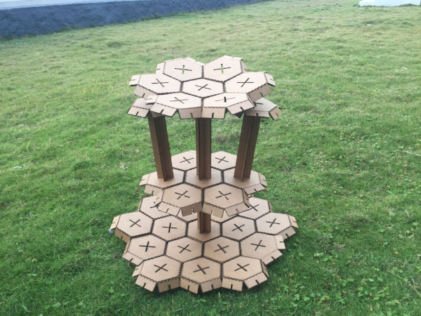
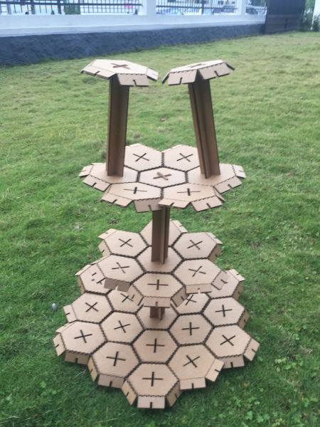
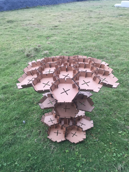
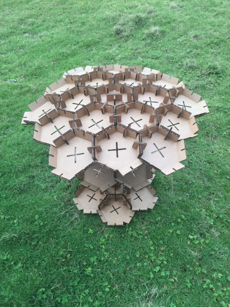
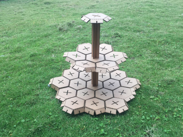
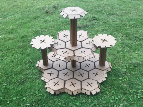
Folding and fitting the hexagons
F. Finally it is show time
G. Problems faces and their solutions
-
I was trying to print a design with size 305 mm x 305 mm and i got an error as in the image
below.
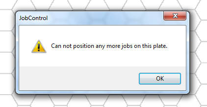
I rechecked all my design everything and made sure that everything is right and tried to print again. This time also i got the same error.Solution
This error was due to the fact that the machine we are having has a maximum print size of 300x600 mm. Anything you try to print beyond this diamension will give you this error.
- If you try to engrave am image which is of low resolution, the output will be really poor. The grays will look thresholded. So it is better to use good quality image for engraving.
- If you ever find that the materials some part is cut and some is not. Or that the cutting width is uneven, them its because you have not fixed the material propoerly on the base. Only the area where the laser could focus properly will be cut properly.
h. Safety Tips
- Avoid cutting acryalite and other plastic material in a close room. The fumes can be harmful. If your room is closed make sure that you have proper ventilation
- make sure that the filter is running before you start the job. This can help the machine stay longer and keep you away from fumes.
- If you are experimenting with materials, have a small research on what that material is consist of and also what gas is generated on oxidation of the material. If there occures harmful gases on oxidation dont try cutting it with laser. Try some other means of cutting.
I. Summary
- Learned to use the vinyl cutter.
- Learned to use the laser cutter
- Understood laser kerf and learned how to compensate for kerf while cutting
- Make a press fit kit using laser cutting, which can be arranged in different ways.

This work is licensed under a Creative Commons Attribution-NonCommercial-ShareAlike 4.0 International License.