16. INTERFACE & APPLICATION PROGRAMMING
Index
- Assignment
- Introduction
- Hall Sensor UI
- Doing the code
- Output
- Text Sender UI
- Doing the code
- Output
- Problems and Solutions
- Summary
A. Assignment
- Write an application that interfaces with an input and/or output device that you made, comparing as many tool options as possible.
B. Introduction
In this week i am planning to try out different UI option to control and read data from a MC board. The following are the list of things i plan to do.
- Ui for my hall sensor
- LED screen displaying text from the computer with processing and wxpython
C. Hall sensor UI
First my plan is to make a ui for the hall sensor board which i made in the input week. The details and
design files of the board is given below.
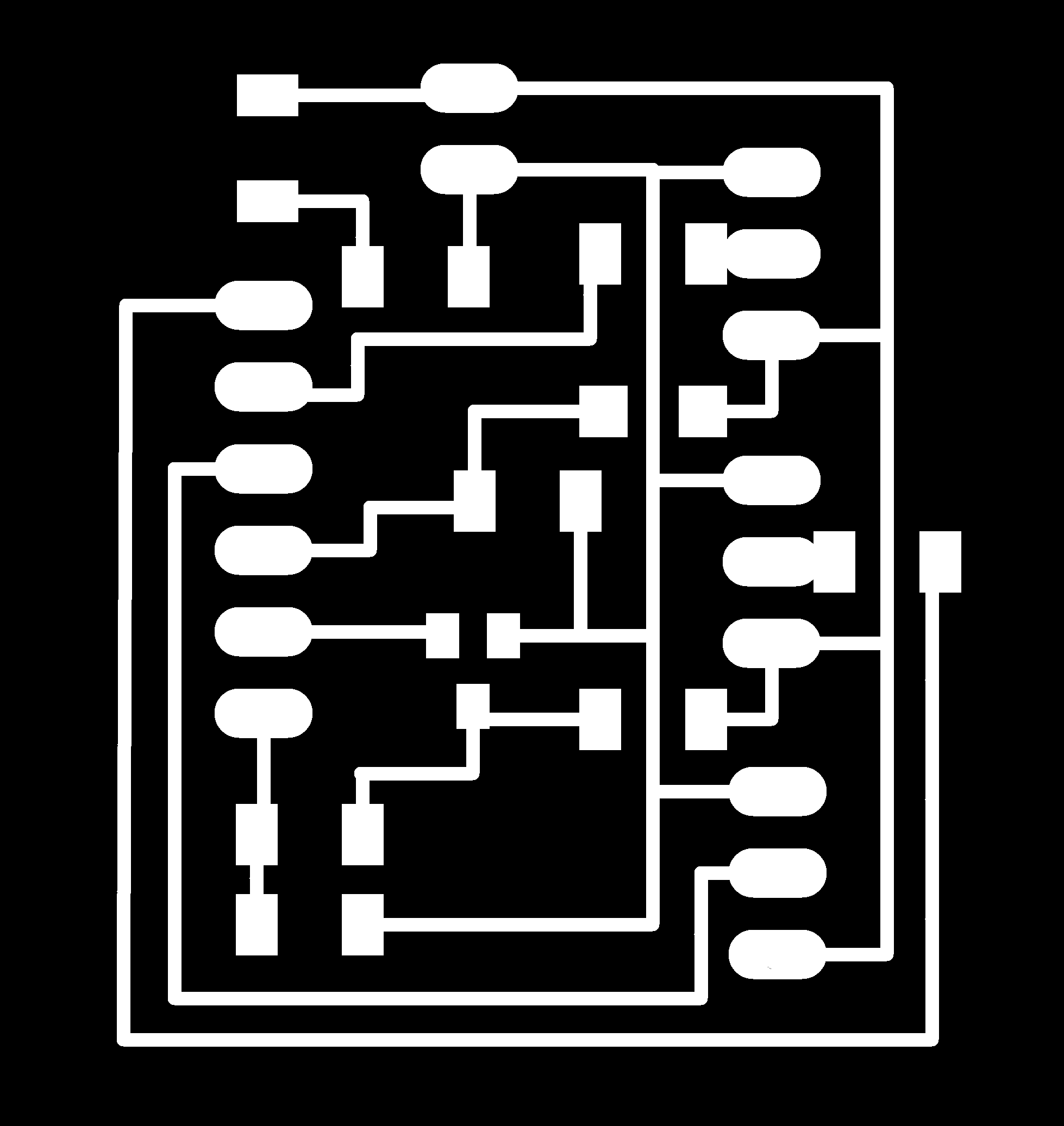
traces image
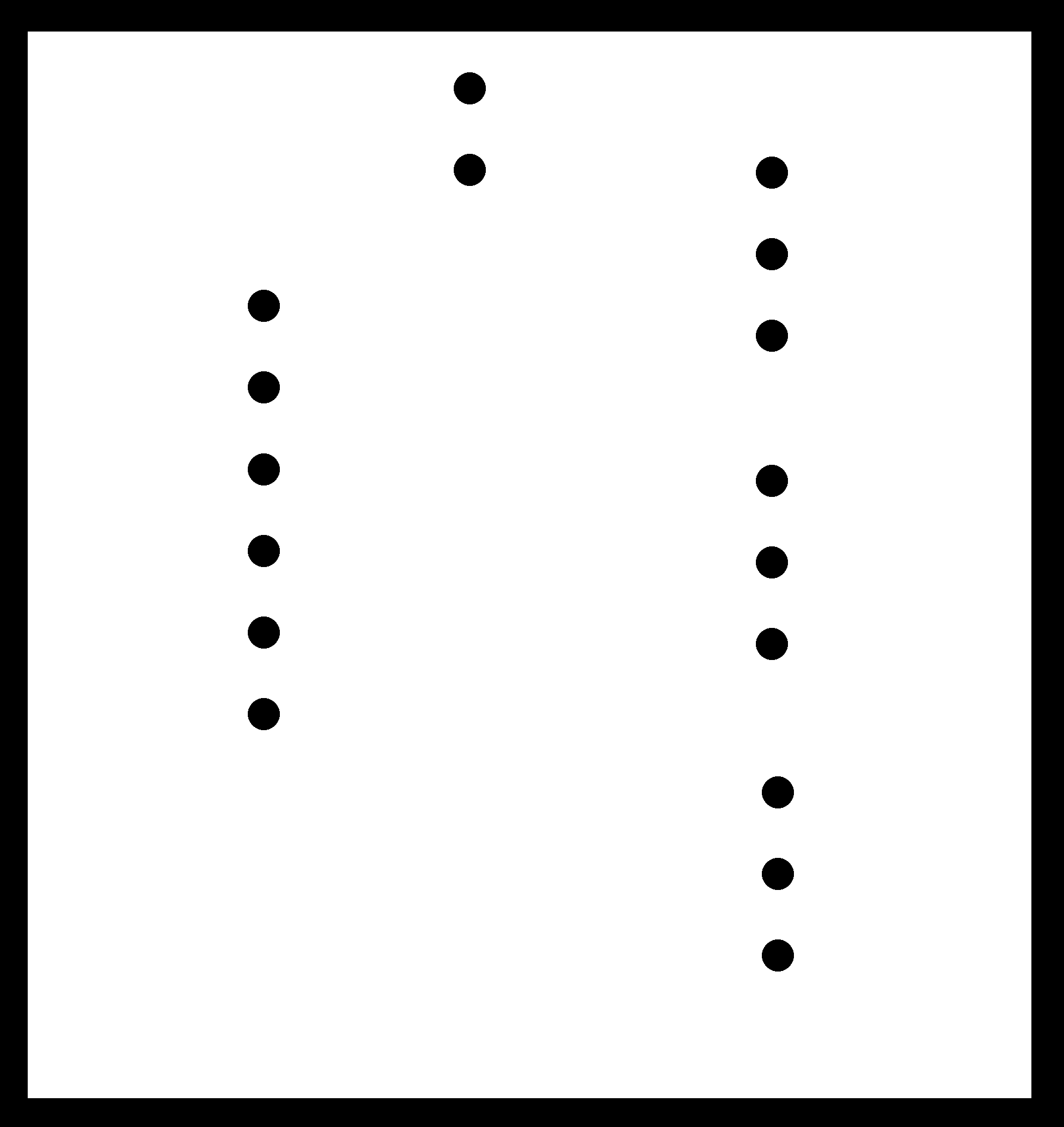
cutout image
Schematic design file
Board design file
I am reusing the board from the output week. The design files are as follows.
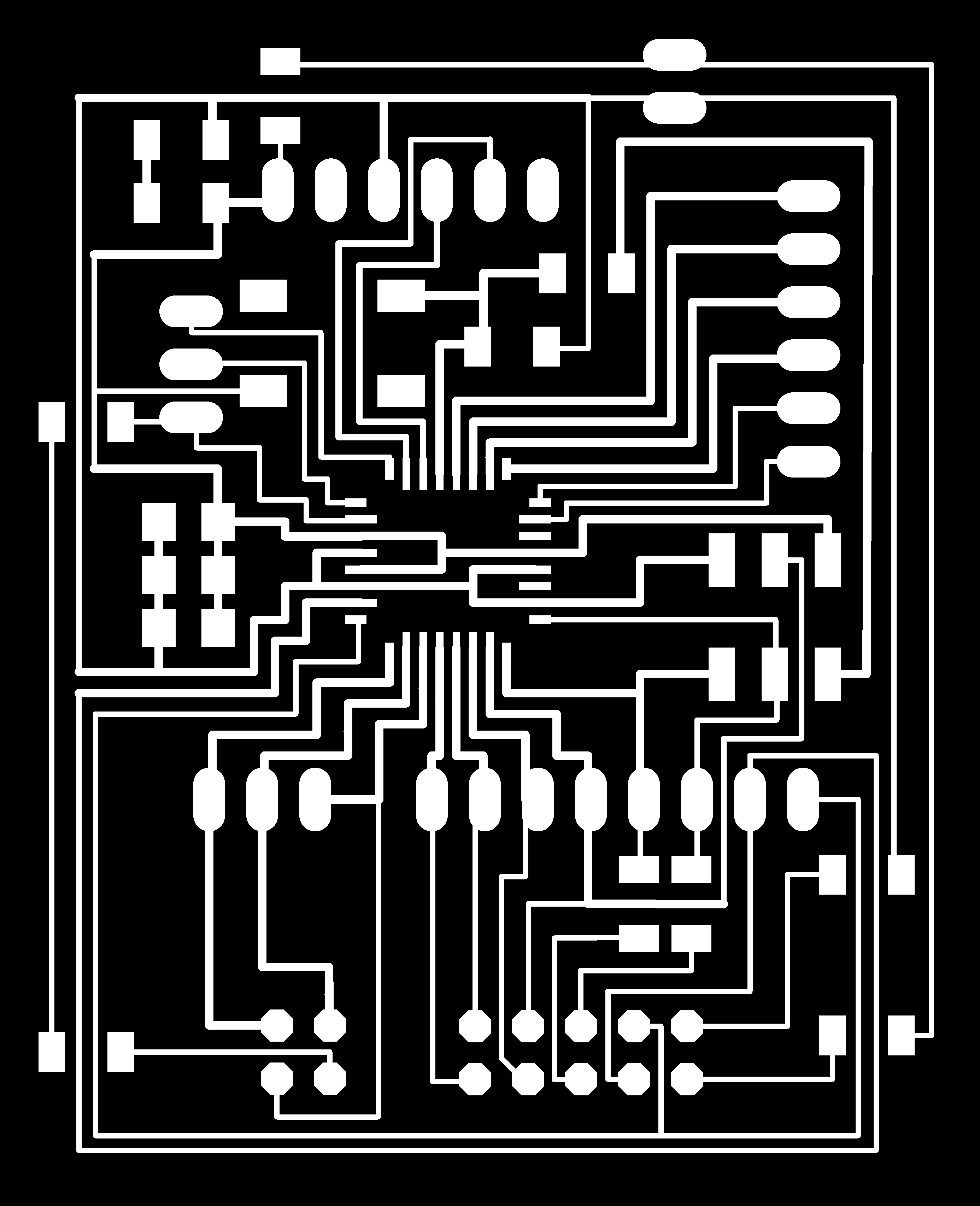
Trace file of the MC board
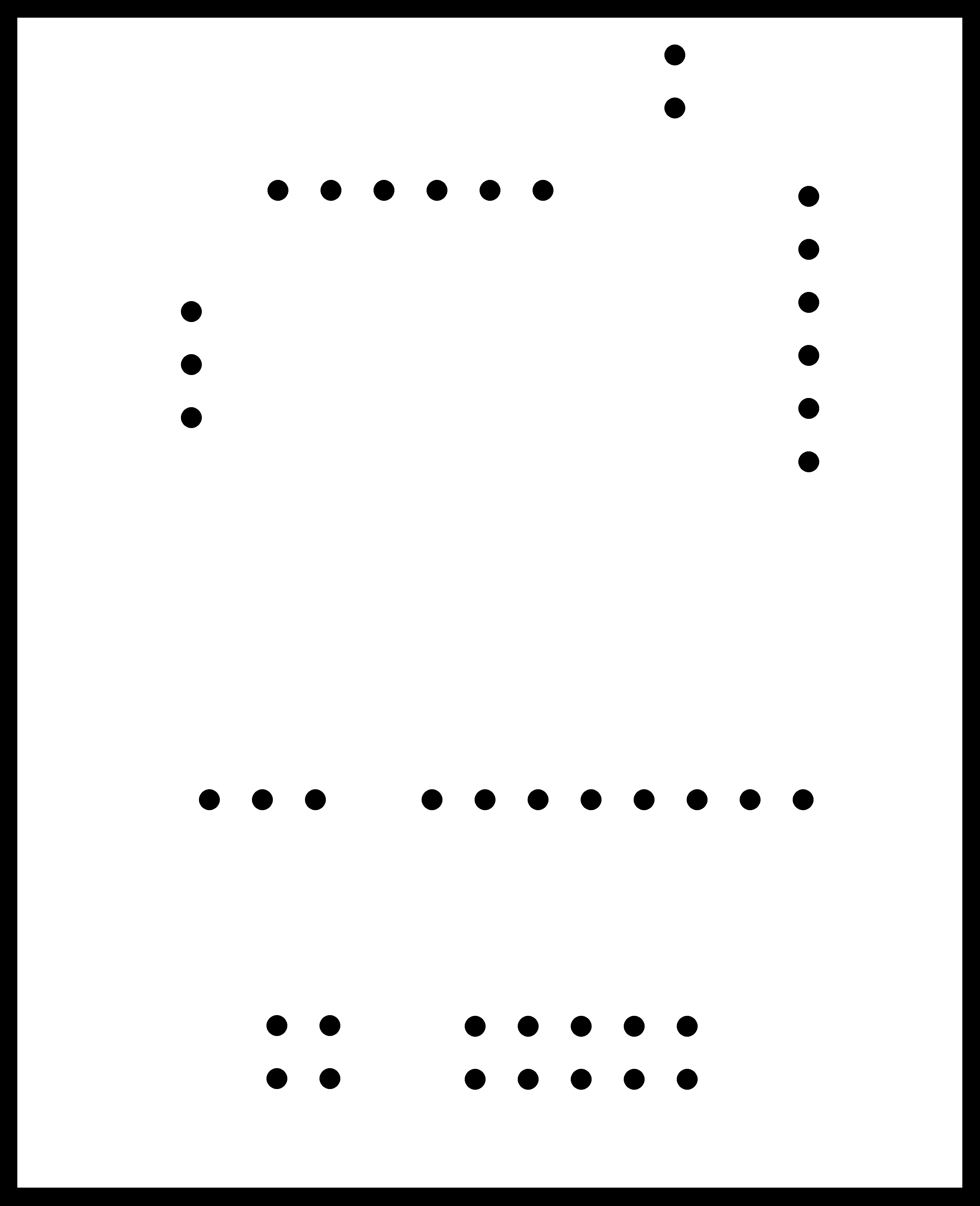
Cut file of the MC board
Schematic design file
Board design file
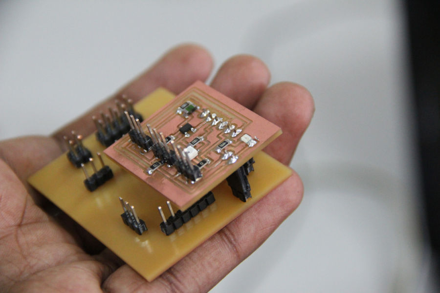
Sensor board clipped to the microcontroller board
c1. Doing the code
As a starting point i am studying Neils magnetic sensor
code.
This code gave me a very good starting point into thinker python ui building. I larned how the code
works and made my own version for the purpose.
The way in which Neils board communicate with the ui and my does are different. I make my own logic to
how data is recieved and represented.
here is the full code.
Source code
In the avr code, the hall sensor data is read and converted by ADC, this data is being send to the
serial. I use the Usart library i made in the networking week to accomplish this.
AVR Source code
- from Tkinter import *
- import serial
- window_width = 600 # window width
- number_of_samples = 100.0 # number of samples taken
- port = "/dev/ttyUSB0"
- #
- # open serial port with supplied port and baud rate. My serial is running in 4800 baud
- #
- serial = serial.Serial(port, 4800)
- serial.setDTR()
- def idle(parent,canvas):
- # crears all the serial data at once
- serial.flush()
- #create a variable to hold the data from the serial
- text = ""
- #keep looping over the serial data
- while 1:
- #read serial char
- data = serial.read()
- # if you find an enter, break the loop
- if (data == '\n'):
- break
- #otherwise keep contacting the string
- text += data
- # convert the string to an integer
- value = int(text)
- print value
- x = int(.2 * window_width + (.9 - .2) * window_width * value / 1024.0)
- canvas.itemconfigure("text",text="%.1f"%value)
- # change the size of the rectangle according to the value
- canvas.coords('rect1', .2 * window_width, .05 * window_width, x, .2 * window_width)
- canvas.coords('rect2', x, .05 * window_width, .9 * window_width, .2 * window_width)
- canvas.update()
- parent.after_idle(idle,parent,canvas)
- # set up ui
- UI = Tk()
- UI.title('hall sensor ui')
- UI.bind('q', 'exit')
- canvas = Canvas(UI, width=window_width, height=.25 * window_width, background='white')
- canvas.create_text(.1 * window_width, .125 * window_width, text=".33", font=("Helvetica", 24), tags="text", fill="#0000b0")
- canvas.create_rectangle(.2 * window_width, .05 * window_width, .3 * window_width, .2 * window_width, tags='rect1', fill='#ffff00')
- canvas.create_rectangle(.3 * window_width, .05 * window_width, .9 * window_width, .2 * window_width, tags='rect2', fill='#0000ff')
- canvas.pack()
- # start loop
- UI.after(100, idle, UI, canvas)
- UI.mainloop()
c2. Output
Here is the output. I am bringing a magnet closer to the sensor and you can see the change in the
value in the ui. The value changes drastically when the poles are changed.
Result
d. Text Sender UI
I made another program in processing which sends the text entered by the user. You see the ui below. In
the text feild enter some text and click the
button below. Once you click the button the LCD displays that text.
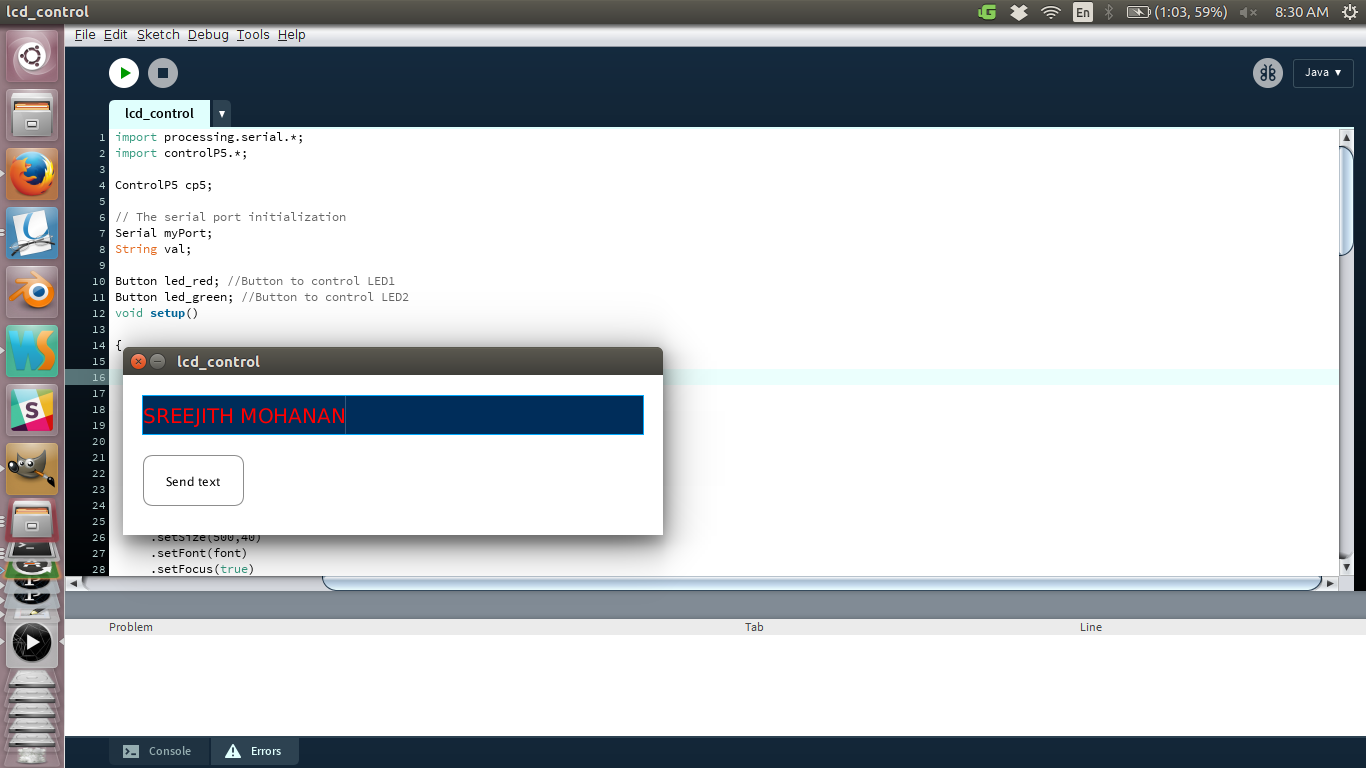
Processing user interface for sending text
Now when i click the button that text is shown on the LCD.
You can see the below ui code it basically initializes a serial communication in the specified port and listens to it.
It then creates a thinker ui, which is basically a window with two rectangles. Now when the ui gets data from the
serial the width of the rectangles are adjusted with respect to the value creating a visual feel of a bar graph
d1. Doing the code
The code is documented within in the file. The files are given below. Basically i have made the
processing ui which has
a text feild as well as the a button. Now when i type something in the field and press the send button,
the text in
the feild is taken and is added with a preceeding '#' and a ';' in the end and is send over serial to my
board.
The board recognizes the sequence and extracts the text between the # and ; and displays it on the LCD.
I am reusing code and board from output week, where i did LCD programming and from newtowrk week where i
make the
USART library.
AVR C File
Processing file
- import processing.serial.*;
- import controlP5.*;
- ControlP5 cp5;
- // The serial port initialization
- Serial myPort;
- String val;
- Textfield myTextfield;
- Button send; //Button to send the text
- void settings(){
- size (540, 160);
- }
- void setup()
- {
- myPort = new Serial(this, "/dev/ttyUSB0", 4800);
- PFont font = createFont("arial",20);
- cp5 = new ControlP5(this);
- myTextfield = cp5.addTextfield("myTextfield")
- .setPosition(20,20)
- .setSize(500,40)
- .setFont(font)
- .setFocus(true)
- .setColor(color(255,0,0))
- ;
- send = new Button("Send text", 20, 80, 100, 50, 255, 255, 255); //Button descriptions
- }
- void draw()
- {
- fill(255);
- background(255);
- send.Draw();
- }
- void mousePressed()
- {
- if (send.MouseIsOver()) //if on button pressed the data is sent over serial
- {
- val = myTextfield.getText();
- println(val); //print it out in the console
- myPort.write('#' +val+';');
- }
- }
- // the Button class definition
- class Button {
- String label; // button label
- float x; // top left corner x position
- float y; // top left corner y position
- float w; // width of button
- float h; // height of button
- int r;
- int g;
- int b;
- // constructor
- Button(String labelB, float xpos, float ypos, float widthB, float heightB, int rVal, int gVal, int bVal) {
- label = labelB;
- x = xpos;
- y = ypos;
- w = widthB;
- h = heightB;
- r = rVal;
- g = gVal;
- b = bVal;
- }
- void Draw() {
- fill(r,g,b);
- stroke(141);
- rect(x, y, w, h, 10);
- textAlign(CENTER, CENTER);
- fill(0);
- text(label, x + (w / 2), y + (h / 2));
- }
- boolean MouseIsOver() {
- if (mouseX > x && mouseX < (x + w) && mouseY > y && mouseY < (y + h)) {
- return true;
- }
- return false;
- }
- }
d2. Results
Result
e. Problems and solutions
- Initially baud rate was a problem, on inspection i found that i was trying to connect with 9800 rate from the processing ui when micro controller was talking at 4800. I changed the value in processing code and it fixed the error.
- I have found a bug in my LCD library. When you call the PutStringAtLocation() function the second time with a smaller string than the initial one, the last charectors will remain. I dont want to edit the library right now so instead a created a work around , that i will put space after the string. ie if i send 'sree' the program will append 59-4 space to the back making a full 60 charector string.
- In the tutorials for processing i refered, the size() function was inside setup() function. but while i was building, it gave me an error saying that "size() can be at this location". This error was fixed by moving the size() function call inside settings() function. This was actually due to an update in the processing 3.
f. Summary
- Experimented with processing and thinker and processing for making UI.
- Make a ui for showing hall sensor output with processing.
- Make a ui for sending text to the microcontroller, which in turn shows it on the LCD display.

This work is licensed under a Creative Commons Attribution-NonCommercial-ShareAlike 4.0 International License.