15. NETWORKING AND COMMUNICATION
Index
- Assignment
- Introduction
- Understanding USART
- USART Registers
- Designing the boards
- Making the PCB
- Making the connections
- Time to Code
- Results
- Problems and Solutions
- Summary
A. Assignment
- Design and build a wired &/or wireless network connecting at least two processors.
B. Introduction
In this week we are working with networking and communication. I plan to try serial
communication for my weeks assignment. Serial communication or USART is a common means of communication
between a computer and a microcontroller as well as between micro controllers. ATmega328 has dedicated
hardware for handling USART. This makes reading and writing data to and from the microprocessor easy.
We can even implement usart in software but that is little tricky and needs a lot of debugging. In this
week
i also plan to make a USART library which can be reused through my project and for other weeks if necessary.
I need to implement a network with two or more microcontrollers for this work.
I will have 3 microcontrollers connected to the computer over a serial bus. One of the
microcontroller will be the master and others the slaves. I will send a slave id and the led's to be
turned ON from the computer to the network, the master alone reads the message and saves it.
After a delay of 1 second the master retransmits the data in a format, the slaves can read.
Now the transmitted data has a node id in it. On receiving this data the node with the
id which is referenced in the transmitted signal will light up the led's as specified in the signal.
With this project i like to experiment with serial communication and implement a simple system for
targeting data to the microcontroler uniquely by its id and making it do something said in the message(ligthiting the respective LED's). I am also trying to implement a quasi-protocol which lets you target data to
a group of microcontrollers at once. Here there are two groups - master or slaves.
C. Understanding USART
USART stands for Universal Synchronous Asynchronous Transmitter/Receiver. It is a communication protocol
used by the micro controller for communication with other microcontollers, pc or even other peripheral
devices. Here the communication takes place through a voltage level shifter and all you need is a shift register
and the buffer. To use USART communication, both the devices first need to agree up on a data transmission speed,
called the baud rate. It is basically the speed at which the voltage shifting happens while sending the data.
The receiver should also recieve the data at the same speed else, the data get corrupted. This the baud rate is very
important. Next thig they need is a data frame, which is very much like the data format. Both the MC need to agree on
a data frame. USART can operate in either synchronous as well as asyn mode. The difference is that in the sync mode
instead of agreeing upon the baud there will be a clock line for data synchronization. Here we are interested the async
mode so further description is about that mode only.
Thus we can see that USART communication is very simple, you agree up on a speed, the data format called the data frame and
you are ready for communication. When initialized the the data line is in waiting mode. Now you send the data to
the data register. This data is taken up by the MC and the particular formatting is applied and is send over to the receiver.
The receiver get the data and interprets the content. With that said lets get into the register description. And yes the
Atmega328 pu has an inbuild USART hardware which makes things as easy as changing a few register. This page provides very comprehensive and easy to digest details about USART.
e. Designing the boards
USART only needs the tx and rx pins for communication but its a good practice to connect the
ground and vcc also. As like the input and output week this week also i am not making a microcontroller
board but instead reusing my earlier board and just creating a new board which can be pinned on top
of it as an extra module. The design files are given below. Making a board which can be pinned on top
of another with headers is quite tricky and you need to be vey careful about the pin positions. The
new board needs to be mirrored and made if you want the female pins to properly go into the male pins.
I am sharing my design files here
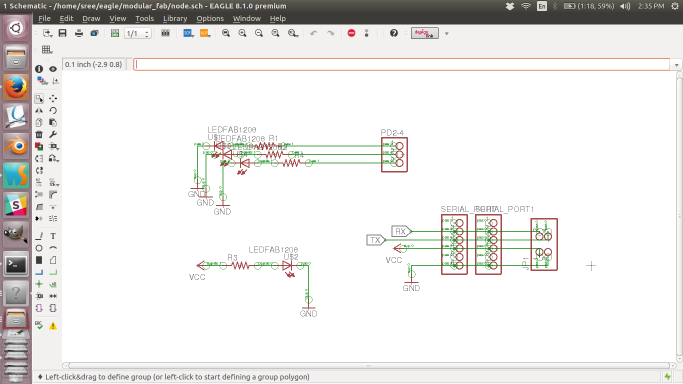
Board schematics
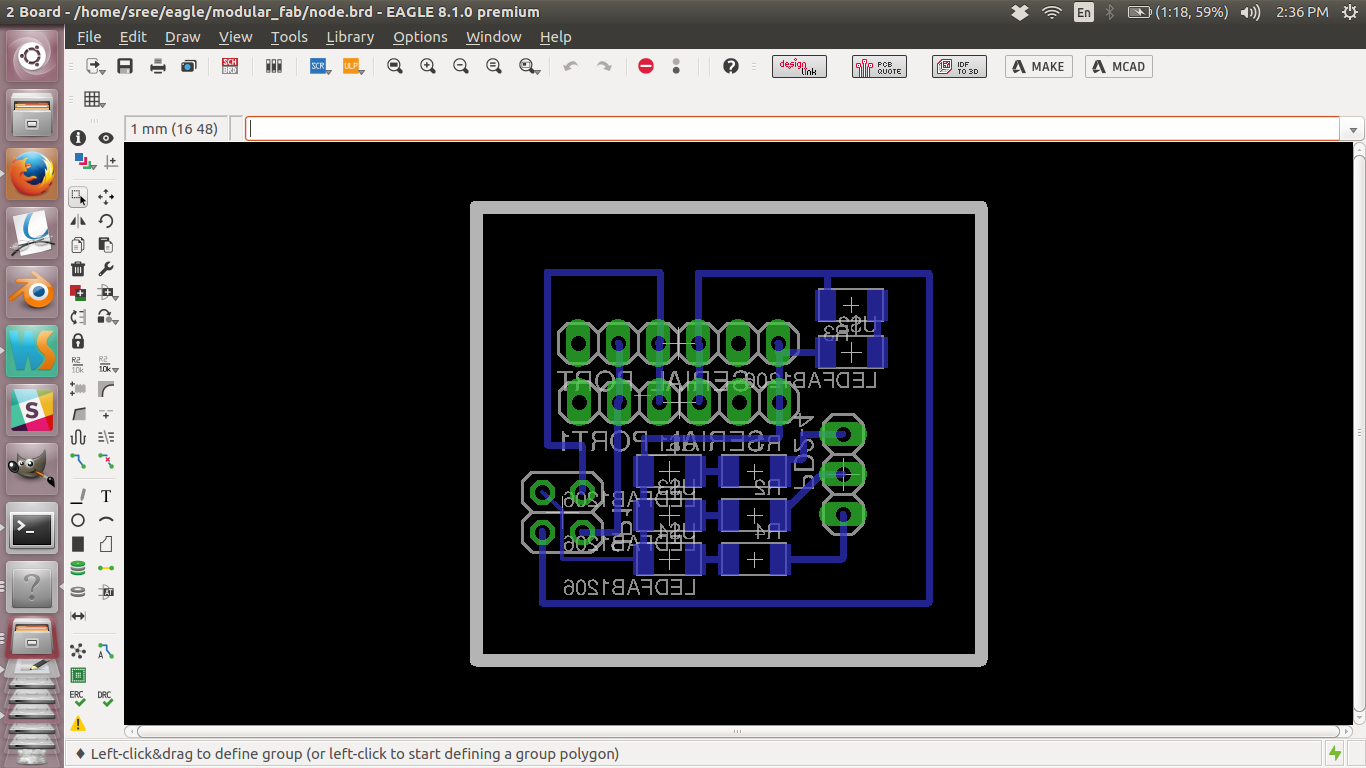
Board layout
Original scnematics file
Original board layout file
I am reusing the board from the output week. The design files are as follows.
Trace file of the MC board
Cut file of the MC board
Schematic design file
Board design file
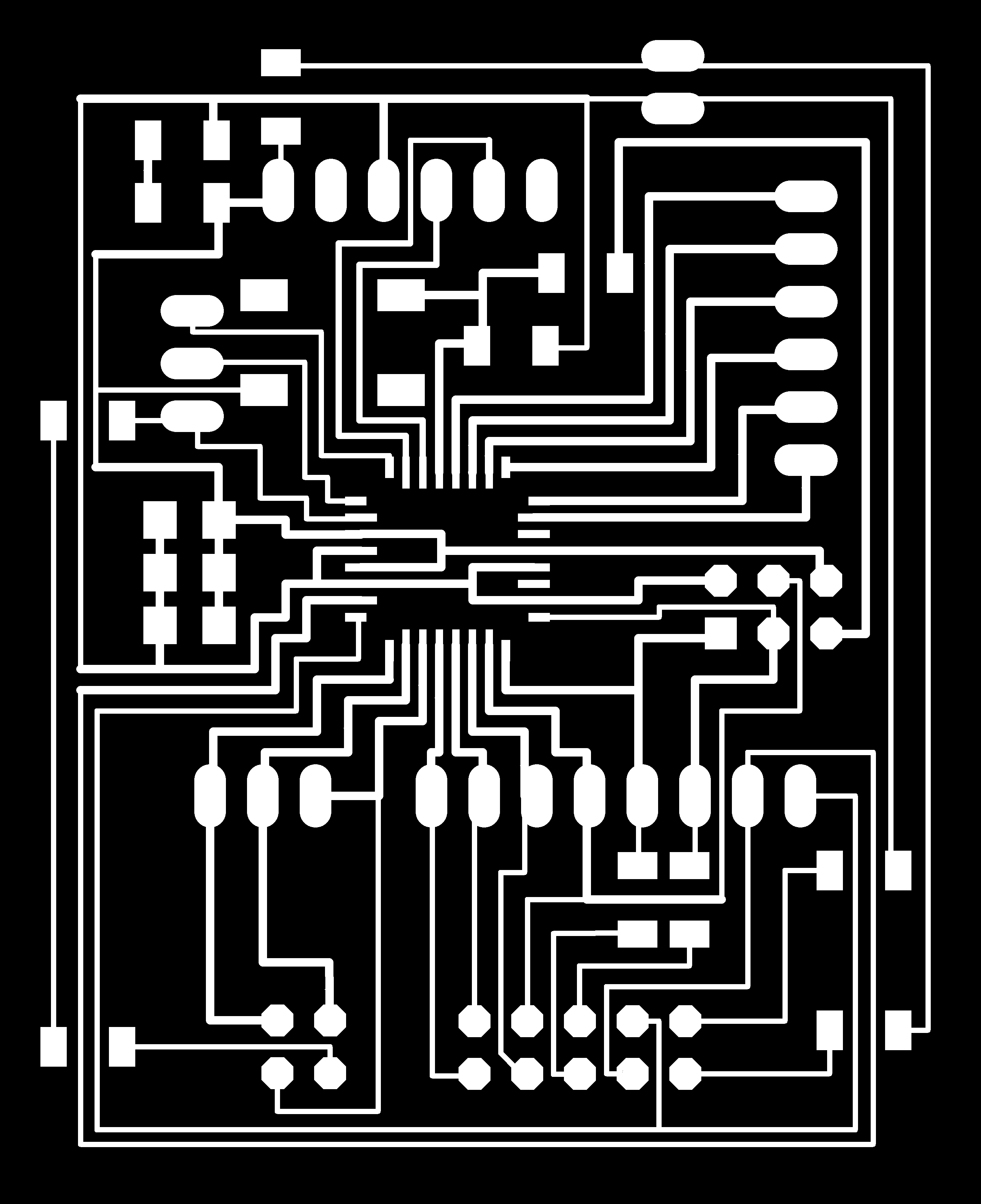
f. Making the PCB
Then i created the monochrome png images for milling and cutting. Those images in full resolution
are given
below.
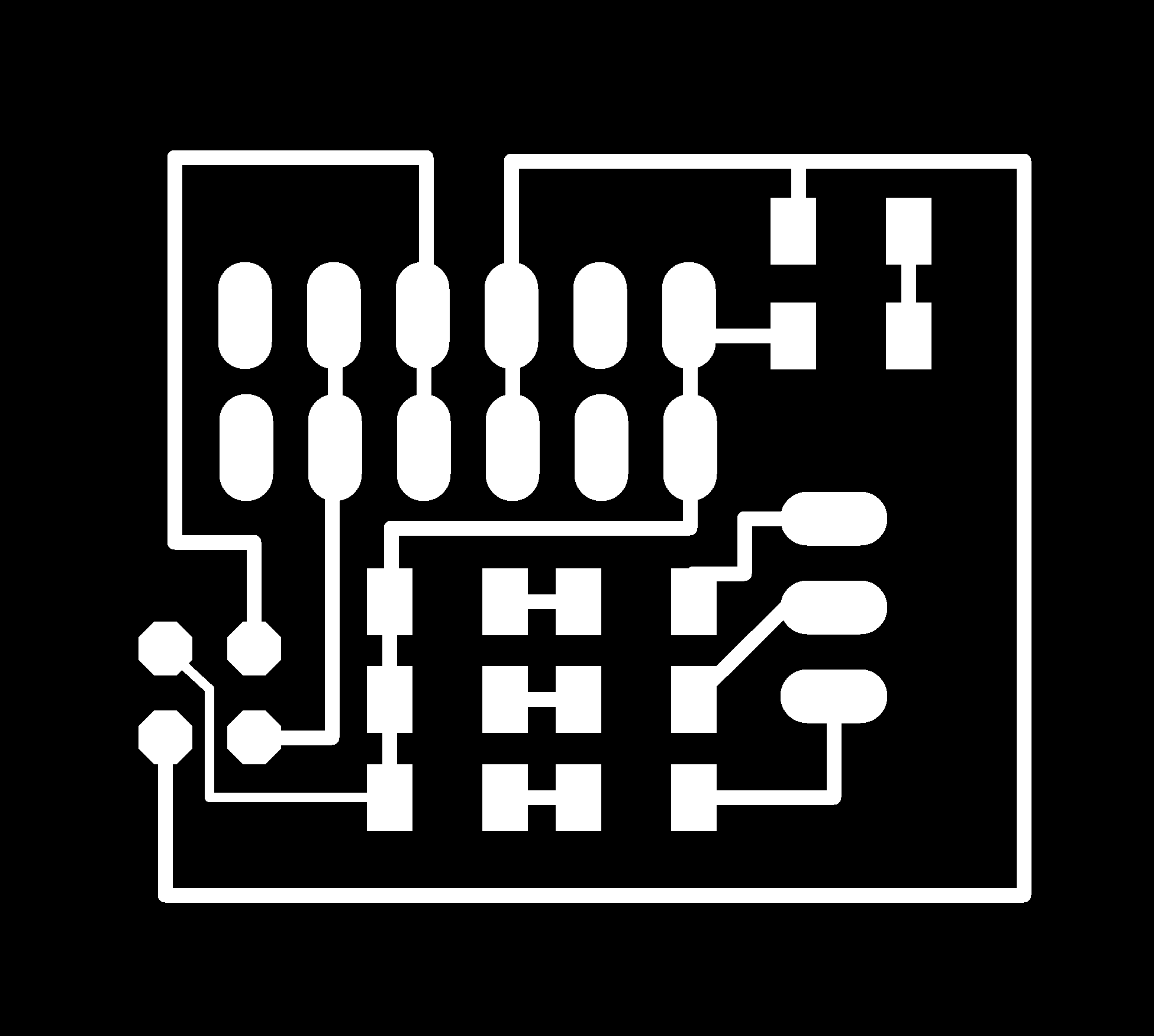
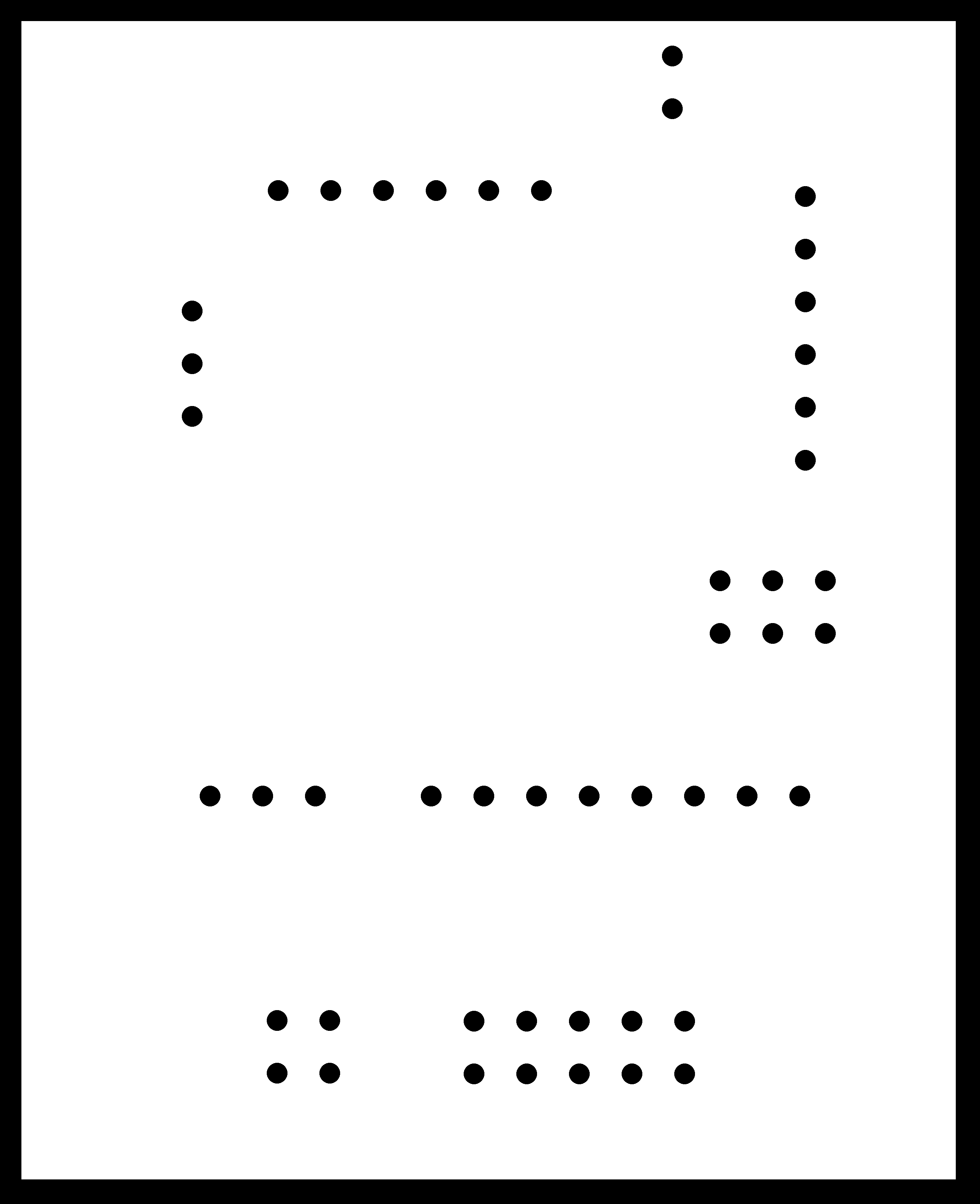
traces image
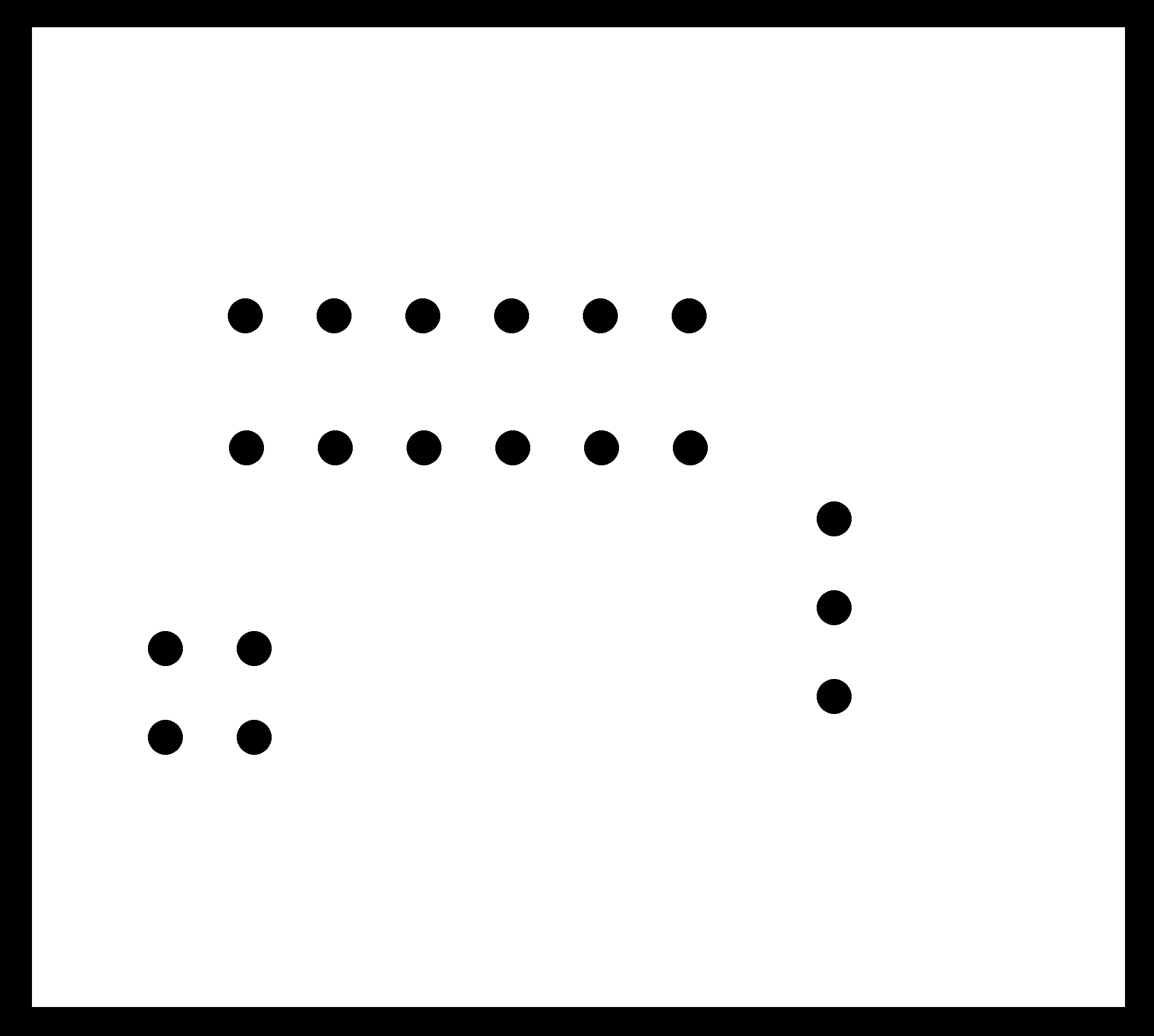
cutout image
Later i used modella and fab modules to mill and cut the board. Then i collected necessary
components for the board and sticked them side by side to the printout of the
pcb which i designed. This is something i suggest while soldering. Make sure that you have a
printout of the pcb with components and also have the components sticked corresponding to their name
and value. This will save a lot of time. Finally i started soldering and successfully soldered all the
components. This is the finished board pinned through header to the microcontroller board.
I make two
such board and connected then to two microcontroller boards. I am also reusing the microcontroller board
without the LCD connectors made in the output week.
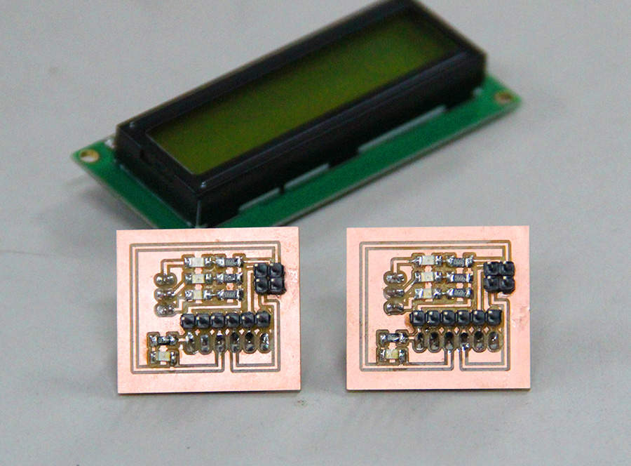
Final Board
You can see that this is a simple board with just 3 leds on it. The board also extends the serial pins in my main board so that i can have a
common rail going between the boards. Thus the two board pair together have a atmega328 microcontroller and 3 leds and a serial port(tx, rx vcc and gnd).
g. Making the connections
You can see 3 boards in the image. The small board is the master board and the other two are the slaves.
the slaves have three leds embedded on them. The serial cable connects all the three boards and the computer.
The main board will receive an instruction set from the computer containing the id of the slave board and the LEDs which needs to be lighted.
The master board saves the message and waits for a second and after that sends this instruction set into the network. Now the slave which
is addressed in the instruction set responds by lighting the requested leds.
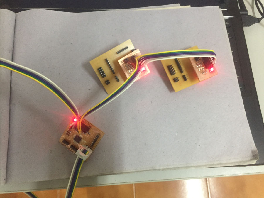
Boards connected
h. Time to Code
ATmega328 has build in hardware to handle the USART. I am creating a library for easy use
of serial communication. For more information about the serial communication refer the following links.
Usart details
Chip to chip communication with usart
h1. USART registers
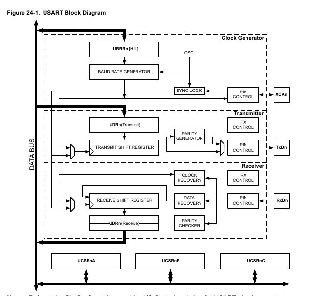
Block diagram
- USART I/O Data Register 0: UDR0
This is the data register, you get and put data in this register. Remember that this register shared among sending and receiving but this is intelligently handled by the controller.
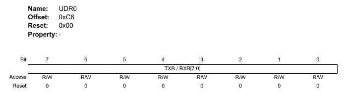
- Bits 7:0 – TXB / RXB[7:0]: USART Transmit / Receive Data Buffer
These bits store the recieve and transmit data.
- Bits 7:0 – TXB / RXB[7:0]: USART Transmit / Receive Data Buffer
- UCSR0A- USART Control and Status Register 0 A
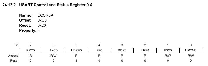
- Bit 7 – RXC0: USART Receive Complete
This is a flag bit set on receive complete
- Bit 6 – TXC0: USART Transmit Complete
This is a flag bit set on transmit complete - Bit 1 – U2X0: Double the USART Transmission Speed
This bit only has effect for the asynchronous operation. Write this bit to zero when using synchronous operation. Turning this bit ON will reduce the divisor of the baud rate divider from 16 to 8 effectively doubling the transfer rate for communication.
- Bit 7 – RXC0: USART Receive Complete
- UCSR0C- USART Control and Status Register 0 C
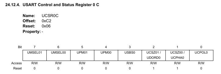
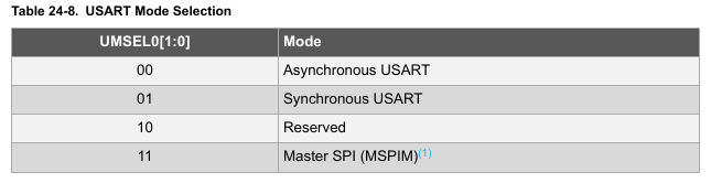
- Bits 7:6 – UMSEL0n: USART Mode Select 0 n [n = 1:0]
This bits select the mode of operation of USART
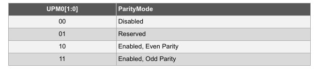
- Bits 5:4 – UPM0n: USART Parity Mode 0 n [n = 1:0]
These bits ar for parity check enabling and generation
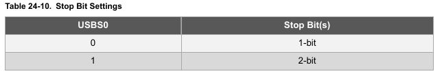
- Bit 3 – USBS0: USART Stop Bit Select 0
This bits set the number of stop bits.
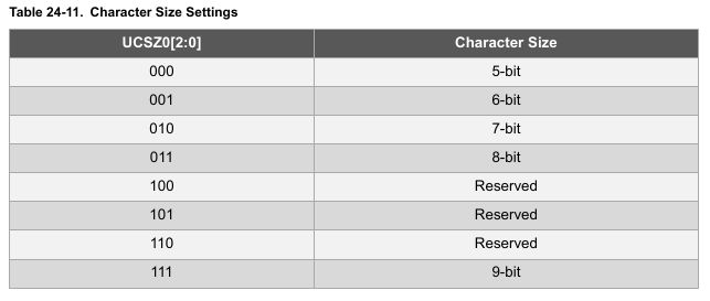
- Bit 2 – UCSZ01 / UDORD0: USART Character Size / Data Order
These bits combined with the UCSZ02 bit in UCSR0B sets the number of data bits (Character Size) in a data frame.
- Bits 7:6 – UMSEL0n: USART Mode Select 0 n [n = 1:0]
- USART Baud Rate 0 Register Low
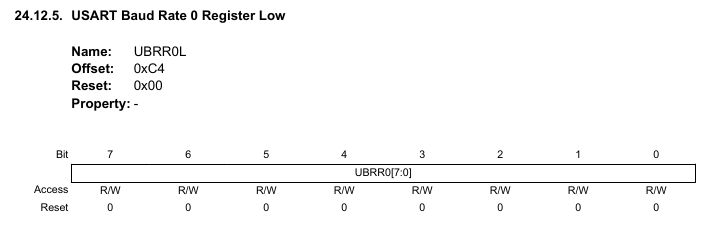
- Bits 7:0 – UBRR0[7:0]: USART Baud Rate 0
This is a 12-bit register which contains the USART baud rate. The UBRR0H contains the four most significant bits and the UBRR0L contains the eight least significant bits of the USART baud rate. Writing UBRR0L will trigger an immediate update of the baud rate prescaler.
- Bits 7:0 – UBRR0[7:0]: USART Baud Rate 0
- USART Baud Rate 0 Register High
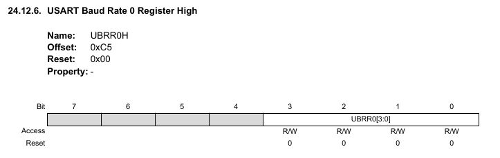
- Bits 3:0 – UBRR0[3:0]: USART Baud Rate 0 n [n = 11:8]
This work together with UBR low register.
- Bits 3:0 – UBRR0[3:0]: USART Baud Rate 0 n [n = 11:8]
h2.Source Code and Explanations
USART.c
- #include "USART.h"
- // function to recieve byte
- unsigned char RecieveByte(void){
- // check to see if the Recieve Complete(RXC0) is set in UCSR0A, ie when ready to recieve
- while (! (UCSR0A & (1 << RXC0)) );
- // one the RXC0 is set the byte is returned
- return UDR0;
- }
- // function to transmit byte
- void TransmitByte(unsigned char data){
- // check to see if the USART Data Read Enable bit is set. This happends when the MC is ready to transmit
- while (! (UCSR0A & (1 << UDRE0)) );
- // data to be send is set to USART Data register
- UDR0 = data;
- }
- // function to initialize the USART( here async mode)
- void InitUART(int baud, char asyncDoubleSpeed, char DataSizeInBits, char parityEvenOrOdd, char stopBits, char USARTInterruptEnable){
- // finding the USART Baud rate register value
- uint16_t UBBRValue = lrint((F_CPU / (16L * baud) ) - 1);
- // setting if 2x speed needed or not on Control and Status Register A
- if(asyncDoubleSpeed == 1) UCSR0A = (1<<U2X0);
- //Put the upper part of the baud number here (bits 8 to 11)
- UBRR0H = (unsigned char) (UBBRValue >> 8);
- //Put the remaining part of the baud number here
- UBRR0L = (unsigned char) UBBRValue;
- //Enable the receiver and transmitter
- UCSR0B = (1 << RXEN0) | (1 << TXEN0);
- // enabling the Recieve complete Interrupt Enable
- if(USARTInterruptEnable) UCSR0B |= (1 << RXCIE0);
- //Set 2 stop bits and data bit length is 8-bit
- if( stopBits == 2) UCSR0C = (1 << USBS0);
- if(parityEvenOrOdd == EVEN) UCSR0C |= (1 << UPM01); //Sets parity to EVEN
- if(parityEvenOrOdd == ODD) UCSR0C |= (3 << UPM00); //Set parity to ODD
- if(DataSizeInBits == 6 ) UCSR0C |= (1 << UCSZ00); //6-bit data length
- if(DataSizeInBits == 7 ) UCSR0C |= (2 << UCSZ00); //7-bit data length
- if(DataSizeInBits == 8 ) UCSR0C |= (3 << UCSZ00); //8-bit data length
- if(DataSizeInBits == 9 ) UCSR0C |= (7 << UCSZ00); //9-bit data length
- }
- /* Here are a bunch of useful printing commands */
- void printString(const char myString[]) {
- uint8_t i = 0;
- while (myString[i]) {
- TransmitByte(myString[i]);
- i++;
- }
- }
- void printByte(uint8_t byte) {
- /* Converts a byte to a string of decimal text, sends it */
- TransmitByte('0' + (byte / 100)); /* Hundreds */
- TransmitByte('0' + ((byte / 10) % 10)); /* Tens */
- TransmitByte('0' + (byte % 10)); /* Ones */
- }
- void readString(char myString[], uint8_t maxLength) {
- char response;
- uint8_t i;
- i = 0;
- while (i < (maxLength - 1)) { /* prevent over-runs */
- response = RecieveByte();
- TransmitByte(response); /* echo */
- if (response == '\r') { /* enter marks the end */
- break;
- }
- else {
- myString[i] = response; /* add in a letter */
- i++;
- }
- }
- myString[i] = 0; /* terminal NULL character */
- }
Code Review
The above code is from USART.c file which is the library which is used to bring in serial communication. This is the core of this
weeks assignment. The atmega328 has an in-build hardware to handle serial communication. Using this is as easy as configuring some
registors. I have commented all the register and their functionality within the code. The most importent functions over here are
the InitUART which initialized a uart connection. It also enables the tx and rx registers and does other bootstraping.I have made this
function as generic as possible that it can be used with different baud rates and data frames. basically a data frame is like
the sequence in which you send the data. Usually in a dataframe you will hav a start bit, data bit parity bit and stop bit.
Start bit informs the MC to start reading the data. The data bits are usaually 6 7 8 or 9. I like to use 8. Then you have a pariety byte
which is optinal and lastley the stop bits. I see people using 2 stop bits but i think 1 will also do.
Other important functions are TransmitByte and RecieveByte, used to transmit and recieve bytes. I also have few helper functions to send a string
or an integer.
The logic of operation is that, i send a sequence - #0101; to the network which only the master board will read and save.
The first 0 in the sequence is the unique id of the node which this instruction is targeted to .The following 101 means i want to light
first and third led in the 0th node. Now the master gets and saves this information and waits for a second. After the wait the board send
another sequence ie $0101; which the nodes can receive. Both node listens to the data, but the node with the refered id will only respond, by
lighiting up the asked sequence.
master.c
- #include <stdlib.h>
- #include "USART.h"
- #include <avr/interrupt.h>
- #include <util/delay.h>
- #define UNINITIALIZED 0
- #define RECEIVE 1
- #define OPERATE 2
- static volatile unsigned char data;
- volatile char command[60];
- volatile char slaveCommand[60];
- volatile unsigned char commandLength = 0;
- volatile unsigned char state = UNINITIALIZED;
- ISR(USART_RX_vect){
- data = UDR0;
- if(data == '#'){
- state = RECEIVE;
- }
- if(data == ';' && state == RECEIVE){
- slaveCommand[0] = '$';
- int i;
- for(i=0; i< commandLength; i++){
- slaveCommand[i+1] = command[i];
- }
- slaveCommand[commandLength +1] = ';';
- _delay_ms(1000);
- printString((char*)slaveCommand);
- state = OPERATE;
- for(i=0; i< 59; i++){
- command[i] =' ';
- }
- commandLength=0;
- }
- if(state == RECEIVE && data != '#'){
- command[commandLength] = data;
- commandLength++;
- }
- }
- int main(void)
- {
- InitUART(4800, 0, 8, NONE, 1, TRUE);
- sei();
- while(1)
- {
- }
- }
Code Review
This code waits to receive '#' sign. Once # is received the remaining data is stored in an array
till it get a ';'. On receiving the ';' which means end of message, the microcontroller adds a '$'
infront and ';' in the back to the mesage stored in the array. Now it waits for a second and sents that modified data into the bus which will be later recieved by the nodes.
node.c
- #include <stdlib.h>
- #include "USART.h"
- #include <avr/interrupt.h>
- #include <util/delay.h>
- #include <avr/io.h> // Include AVR library
- #define UNINITIALIZED 0
- #define RECEIVE 1
- #define OPERATE 2
- #define LED_DDR DDRD
- #define LED_PORT PORTD
- #define LED_1 (1<< PD2)
- #define LED_2 (1<< PD3)
- #define LED_3 (1<< PD4)
- //change this is other nodes
- #define id '1'
- static volatile unsigned char data;
- volatile char command[60];
- volatile unsigned char commandLength = 0;
- volatile unsigned char state = UNINITIALIZED;
- ISR(USART_RX_vect){
- data = UDR0;
- if(data == '$'){
- state = RECEIVE;
- }
- if(data == ';' && state == RECEIVE){
- if(command[1] == id){
- if(command[2] == '1'){
- LED_PORT |= LED_1;
- }
- if(command[3] == '1'){
- LED_PORT |= LED_2;
- }
- if(command[4] == '1'){
- LED_PORT |= LED_3;
- }
- }
- _delay_ms(1000);
- LED_PORT &= 0b11100011;
- state = OPERATE;
- int i;
- for(i=0; i< 59; i++){
- command[i] ='\0';
- }
- commandLength=0;
- }
- if(state == RECEIVE && data != '#'){
- command[commandLength] = data;
- commandLength++;
- }
- }
- int main(void)
- {
- InitUART(4800, 0, 8, NONE, 1, TRUE);
- sei();
- LED_DDR = 0b00011100;
- while(1)
- {
- }
- }
Code Review
The main logic is implemented inside the USART receive complete interrupt. Once a byte is received
the code checks if the received character is '$'. So the node waits till it gets a '$'.
Once a '$' is received each node checks the first character after the $ sign. The first character
after the '$ sign is the node id. By checking this each node understands if that data is targeted to
it. IF the character and node id matches the next 3 characters are read. These characters is either 0 or 1
The first character represents LED1 second LED2 and third LED3. So that means if the 3 characters is
010 the information is to turn on LED 2 and keep LED1 and LED3 OFF.
The microcontroller does as instructed, ie lighting the led. Then it waits for a second and again waits
for '$'
Full source code
i. Results
You can see that as i send the board id followed by the led number the corresponding boards
responds by lighting that particular LED's.
Final result
j. Problems and solutions
- While i was testing the usart by sending char from the board to the computer, intially i was getting junk data. The issue was with my baud rate. I was using 9600 baud rate intialy and i did not have an external resonator rather used the internal one. When i referd to the datasheed for this i found that the error rate for usart with internal clock is 12.5% at 9600 baud rate and only less that 2% at 4800 baud rate. Now changing the baud rate to 4800 fixed all that issues.
k. Summary
- Learned serial communication.
- Made a couple of boards and established serial communication between those boards.
- Made a USART library

This work is licensed under a Creative Commons Attribution-NonCommercial-ShareAlike 4.0 International License.