11. MACHINE BUILDING
Index
- Assignment
- Continuation
- Making the electromagnet
- Working with gestalt nodes
- Problems and solutions
- Summary
A. Assignment
- Build a personal site describing you and your final project.
- Plan and sketch a potential semester project and add it to your website.
- Upload it to the class archive. Work through a git tutorial.
B. Continuation
In this week we are continuing our work on the FabARM. We are automating the operations
which we did mechanically in the 9th week. This is the final thing we made last week.
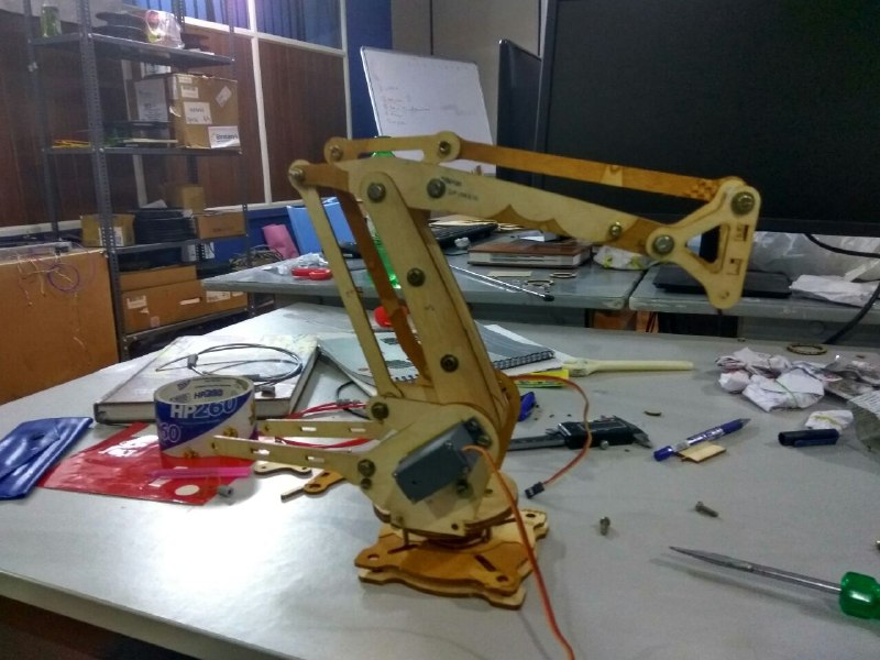
Build from 9th week
This week we are planning to move the arm in a linear path and make it do stuffs like pick and
place, Basic drawing etc. I was assigned the task to make an electromagnet for the pick and place
mechanism.
Link to the group page
c. Making of the electromagnet
The raw materials i could find where a nut and bolt, and insulated copper wire. I know
that
a current carrying conductor will create magnetic field around it . Also that we can create an
electromagnet
by winding such insulated copper wire on a magnetic material like the cut and bolt i am using.I
decided
to
try that out.
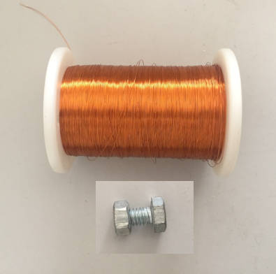
Raw materials
I used the drill to wind the copper wire on the bolt.
Winding the wire with the hand drill
Finally i have my electromagnet.
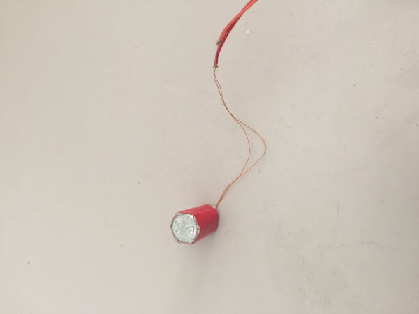
Electromagnet
Electromagnet in action
We have everything in place and its time to make a path for the pick and move motion of the arm.
We used potentiometers to control each servo. I had to find the position of the servos in each point
in
the
motion of the arm. I adjusted each potentiometers and got the points and found the positions of the
servos.
These points where used to automate the motion. The code is attached below.
arm.ino
- //Including the servo library
- #include <Servo.h>
- //define the servos
- Servo servo1;
- Servo servo2;
- Servo serco3;
- int 1 = 100;
- char inByte;
- int a =1;
- //variables identified through calibration with potentiometer
- int valPot1[]={100,100,100,100,102,102,102,118,128,138,145,152,152,157,157,157,157,157,157,157};
- int valPot2[]={139,137,113,88,71,71,71,71,71,71,71,71,71,71,88,100,108,118,117,118};
- int valPot3[]={45,45,45,45,45,86,76,76,76,76,76,76,76,76,76,76,76,56,48,45};
- void setup()
- {
- //Initializing the serial
- Serial.begin(9600);
- //attach the servos to the PWM pins
- servo1.attach(9);
- //setting the start position
- servo1.write(150);
- servo2.attach(10);
- servo2.write(90);
- servo3.attach(11);
- servo3.write(90);
- }
- void loop()
- {
- for(int i=1; i<=19; i++)
- {
- //setting the servo positon to the found value
- servo1.write(valPot1[i]);
- servo2.write(valPot2[i]);
- servo3.write(valPot3[i]);
- delay(500);
- }
- for(int i=19; i>=1; i--)
- {
- servo1.write(valPot1[i]);
- servo2.write(valPot2[i]);
- servo3.write(valPot3[i]);
- delay(500);
- }
- }
Finally we implemented the pick and place mechanism with the electromagnet.
Pick and place
d. Working with Gestalt nodes
As we made the arm to do the pick and place, the next part is to move ahead with the linear guide rail. Initially we where planning to implement a rack and penion mechanism for the linear guide rail. But it didn't succeed due to limited power of the stepper we where using and due to excessive friction in t contacting parts in the rail mechanism. The next option was to try the steppers in the mtm kit. This kit comes with steppers with threaded rods and could be used to move the arm in a single axis. We could fix the stepper to the arm platform without any design change. Finally we did that and then it was time to code the motion. You can get the full source files from github. A detailed documentation on how to get started with gestalt is available here. We followed the link to gather a working knowledge and modified the sample code provided to suite our requirement. The modified code is given below. The original file can be found in examples >> machines >> htmaa folder.
single_node.py
- # Forked from DFUnitVM Oct 2013
- # set portname
- # set location of hex file for bootloader
- #
- #------IMPORTS-------
- from gestalt import nodes
- from gestalt import interfaces
- from gestalt import machines
- from gestalt import functions
- from gestalt.machines import elements
- from gestalt.machines import kinematics
- from gestalt.machines import state
- from gestalt.utilities import notice
- from gestalt.publish import rpc #remote procedure call dispatcher
- import time
- import io
- #------VIRTUAL MACHINE------
- class virtualMachine(machines.virtualMachine):
- def initInterfaces(self):
- if self.providedInterface: self.fabnet = self.providedInterface #providedInterface is defined in the virtualMachine class.
- else: self.fabnet = interfaces.gestaltInterface('FABNET', interfaces.serialInterface(baudRate = 115200, interfaceType = 'ftdi', portName = '/dev/ttyUSB0'))
- def initControllers(self):
- self.xAxisNode = nodes.networkedGestaltNode('X Axis', self.fabnet, filename = '086-005a.py', persistence = self.persistence)
- self.xNode = nodes.compoundNode(self.xAxisNode)
- def initCoordinates(self):
- self.position = state.coordinate(['mm'])
- def initKinematics(self):
- self.xAxis = elements.elementChain.forward([elements.microstep.forward(4), elements.stepper.forward(1.8), elements.leadscrew.forward(6.096), elements.invert.forward(True)])
- self.stageKinematics = kinematics.direct(1) #direct drive on all axes
- def initFunctions(self):
- self.move = functions.move(virtualMachine = self, virtualNode = self.xNode, axes = [self.xAxis], kinematics = self.stageKinematics, machinePosition = self.position,planner = 'null')
- self.jog = functions.jog(self.move) #an incremental wrapper for the move function
- pass
- def initLast(self):
- # self.machineControl.setMotorCurrents(aCurrent = 0.8, bCurrent = 0.8, cCurrent = 0.8)
- # self.xyzNode.setVelocityRequest(0) #clear velocity on nodes. Eventually this will be put in the motion planner on initialization to match state.
- pass
- def publish(self):
- # self.publisher.addNodes(self.machineControl)
- pass
- def getPosition(self):
- return {'position':self.position.future()}
- def setPosition(self, position = [None]):
- self.position.future.set(position)
- def setSpindleSpeed(self, speedFraction):
- # self.machineControl.pwmRequest(speedFraction)
- pass
- #------IF RUN DIRECTLY FROM TERMINAL------
- if __name__ == '__main__':
- stage = virtualMachine(persistenceFile = "test.vmp")
- #stage.xNode.loadProgram('../../../086-005/086-005a.hex')
- #stage.xNode.setMotorCurrent(1)
- stage.xNode.setVelocityRequest(8)
- #f = open('path.csv','r')
- #supercoords = []
- #for line in f.readlines():
- # supernum = float(line)
- # supercoords.append([supernum])
- #stepper moves given as array
- supercoords = [[100],[200],[100],[0],[100],[200],[100],[0],[100],[200],[100],[0],[100],[200],[100],[0]]
- for coords in supercoords:
- stage.move(coords, 0)
- status = stage.xAxisNode.spinStatusRequest()
- while status['stepsRemaining'] > 0:
- time.sleep(0.001)
- status = stage.xAxisNode.spinStatusRequest()
python source code
Linear motion of the arm connected to the stepper
e. Problems faced and their solutions
- The guide rail we build was not working due to excessive friction. We tried to use teflon tape on it, but that actually increased the friction. Due to the friction problem we had to abandon the initial guide rail design and had to proceed with using a stepper from the MTM kit. You can see this is the demo videos.
- The electromagnet which we made was drawing much current that the arduino can provide. The arduino should draw only around 50 milli amphs of current if more current is drawn through it , the circuitry gets damaged and the chip get bricked. So we had to use an external power source for it using a 5v relay controlled by the arduino, this fixed the issue.
- Getting started was quite tricky at first due to the serial port issue. The serial port was found to change between subsequent runs so initially we could'nt get the nodes running. Later it was found that the issue was with loose contact.
- Another issue which we found with the gestalt is that it often the node boards take a long time to respond, so we hav to keep waiting for quit sometime to the see the difference after even a minor code change.
f. Summary
- Together we automated the fabarm.

This work is licensed under a Creative Commons Attribution-NonCommercial-ShareAlike 4.0 International License.