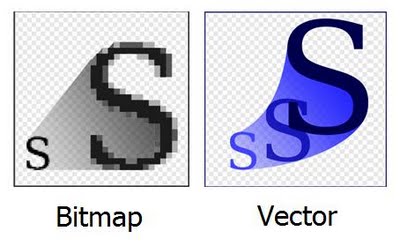
A Raster image is made up of individual pixels. Each pixel contains only one colour and is arranged in a certain fashion to make up the image. This is how normal pictures are displayed. The problem with raster image is that the maximum resolution is limited by the number of pixels.
That means, when you try and scale the image into a larger size, the quality drops and the edges of lines become fuzzy (staircase effect). This is the major limitation of using raster images.
A vector image is composed of paths, which are represented by mathematical functions. These mathematical function represents the actual borders and the different elements in the image. Hence the maximum resolution of the image is not limited by the number of pixels. These mathematical functions can scale easily giving lossless ability to zoom to any extent on the image.
You can erase pixels in a raster image using the eraser tool but, that is not possible in a vector image. In a vector image you can only trim the path according to some constrains.
The different software’s for 2D and 3D design.
2D design
Raster— Gimp, Photoshop, Kirita.
Vector— Inkscape, Adobe Illustrator, Free CAD.
3D Design
Sketchup, FreeCad, 123D, Solidworks, Onshape, Fusion360, Blender, Rhino, Inventor.
I think some elements and tools are common in all the platforms. I’ll try and use as many tools as I can.

Gimp is a free and open source raster graphics editor used for editing and retouching images. It is like a light weight version of Adobe Photoshop. Gimp excels in usability and functionality, it goes beyond simple image editing and gives you the ability to use layers to organize your artwork. There are many common tools in all the raster graphics editors.
I wanted to make an all white Fabacademy logo for my website, hence I downloaded the logo from the Internet and used the Fuzzy select tool to delete the background.
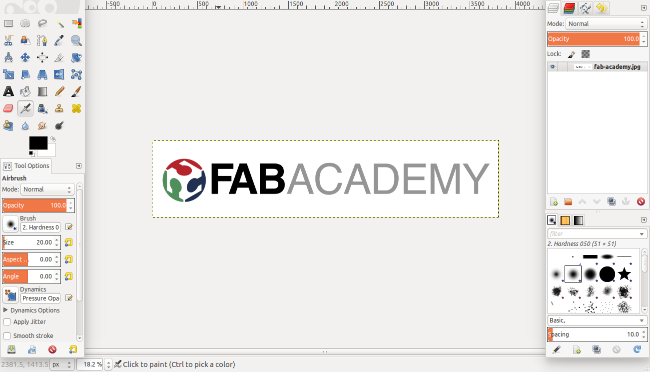
This tool is very easy to use, you click on the background you want to select and the software tries to select pixels similar to the area where you clicked. You can set the tolerance level to the include more or less of the image. Once you have selected the portion you want to remove, press Delete. Now you have an image with a transparent background.

Next I wanted to make the Text all white, Hence I used the Fuzzy select tool again to select individual letters. Now I used the Bucket fill tool to fill the selected portion with white colour.
Combining two images.


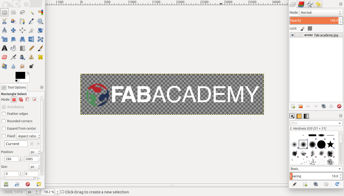
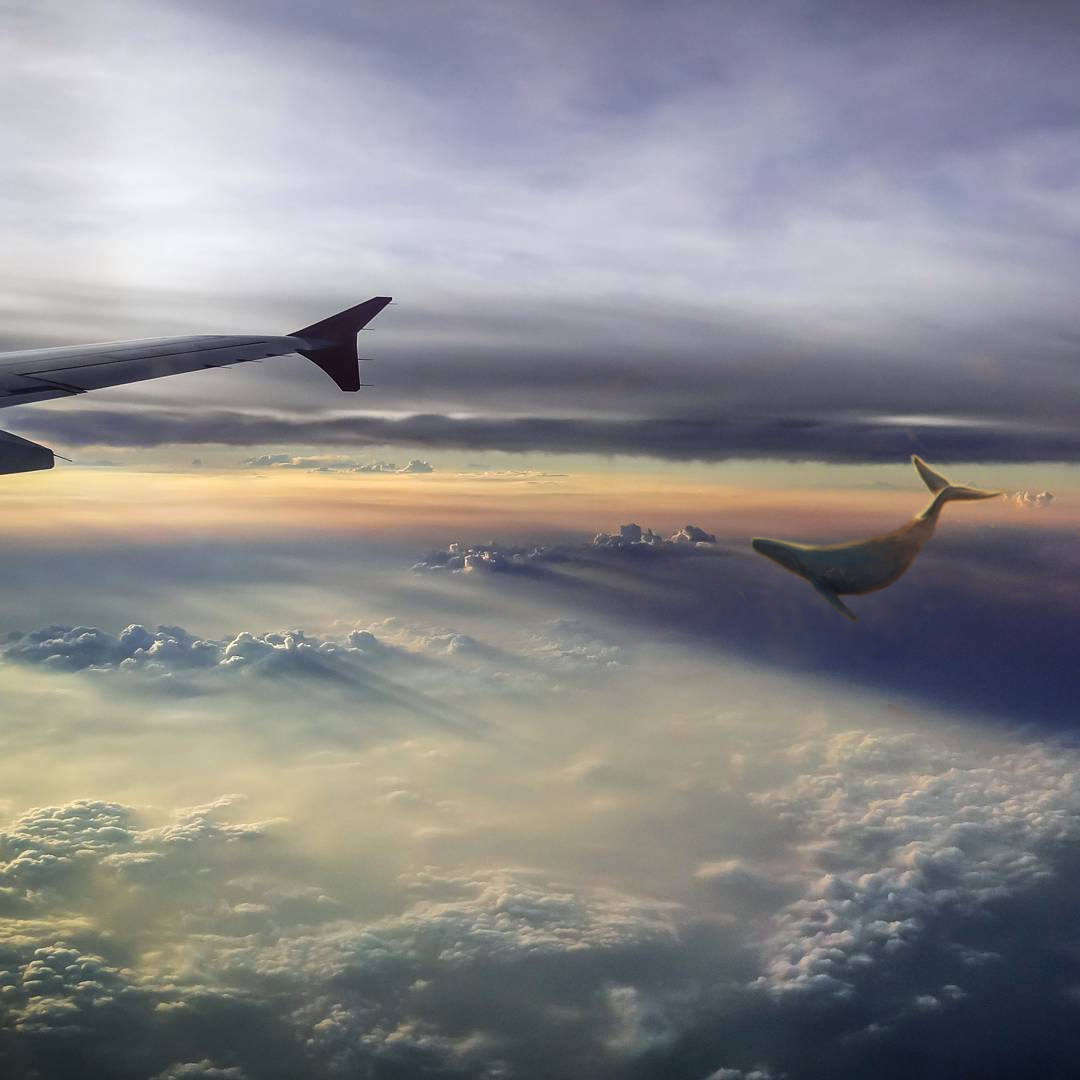
I wanted to blend two images using gimp, hence I chose an image I had taken on a plane in my travels as the background and a fictional image of flying whales from the Internet. I wanted to make it look like the whales are soaring through the clouds besides my plane.
The first task was to separate out the whale from the original artwork. Open the image in gimp and go to layers > transparency > Add alpha layer. This adds a new transparent layer to the image. Now select the eraser tool and erase out the portions of the image you don’t want. Now you can remove the background and leave just the whale intact.
Once you are done, go to File > Export > and export as png image. The png images saves the transparency of the background.
Open a new file by clicking File > New. Now go to File > Open as layers and select the image you want to be in the background. Repeat the same procedure to open the picture of the whale as the foreground. Now both will be combined into a single image. You can edit both the images to get the look you want.

I played with Perspective tool to give the impression that the whale is moving in the same direction as the plane. You can scale down the image by using the Scale tool so that the whale fits into perspective. Use the Blur tool and the Smudge tool to smooth out the boundaries of the image so the it fits into the picture. You can even use the Heal tool to give you a smooth transition between the boundaries of the image. In using the Heal tool you have to first select a source by pressing the Ctrl button and click on the part you want to copy from. Then click and drag on the desired locations.

MyPaint is an opensource raster graphics editor geared towards Digital painters. It is much more fluid in operation than gimp and photoshop. There are a multitude of brushes and colours to choose from. It has all the basic tools to start painting.
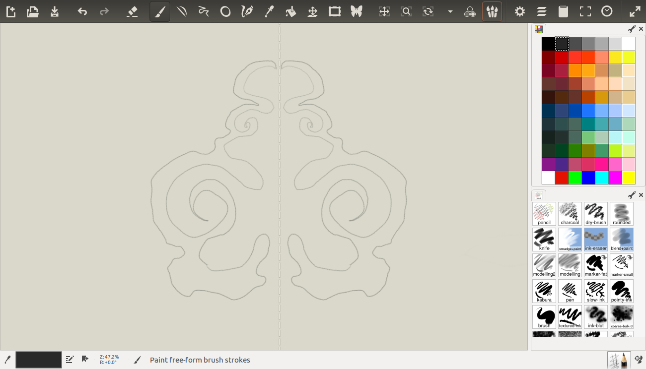
I created an image of a mythical Chinese figure head using the brush tool and the symmetry painting tool, by drawing on the touch pad. Then using different brushes I tried to paint the figure. I liked this software for the its ease of use. You can pick it up in less than 10 mins by playing with all the tools.

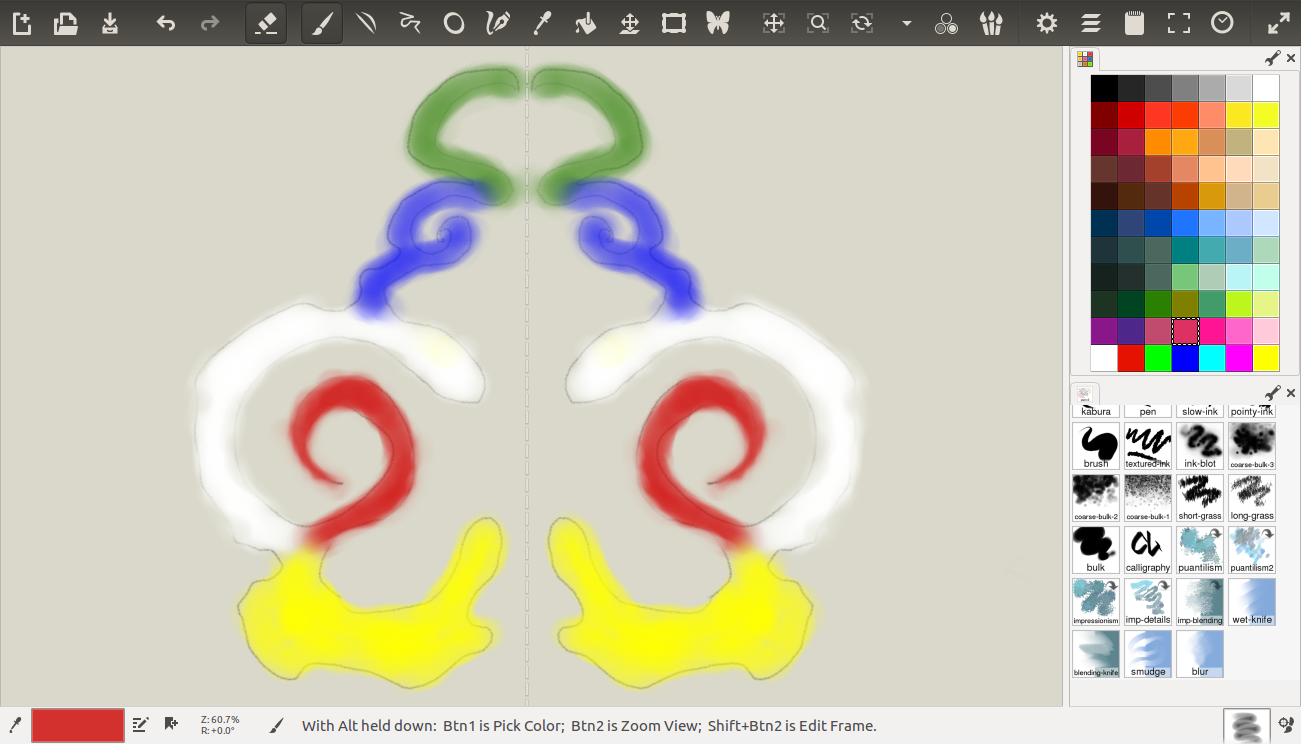
Krita is a raster graphics software. Which is similar to MyPaint but has a lot of customizable features. It is difficult to get your head around the multitude of tools and setting offered by krita. There are a lot of keyboard shortcuts which can ease the flow of work for the user.
I used the touch pad to create this drawing of an apple. There are a lot of brushes to choose from, I tried many and used a few of them to create this art. I really liked this tool of the features it provides. Very powerful software an in the right hands can create beautiful works of art.

I really like this software. The user interface is very intuitive and everything is customizable. Inkscape is used to create vector graphics. Its an open source platform, and you can save your files in an SVG format (Scalable vector Graphics). Which can by viewed in your browser.
The first thing you need to learn to do is to edit your document properties, change the setting to the one you want, you can even put custom dimensions.
Creating guides for drawing is pretty simple, just click and drag from the ruler on both sides to create guides. You can even create a guide form object by drawing an object and clicking Shift + C.
For creating margin and guides at regular intervals, go to Extensions >Render > Guide creator.
For any 2D drawing tool the most important thing you need to know is how to draw smooth curves. This is where the bezier curve come in. Each curve is controlled by 4 points, two of them in the curve itself.
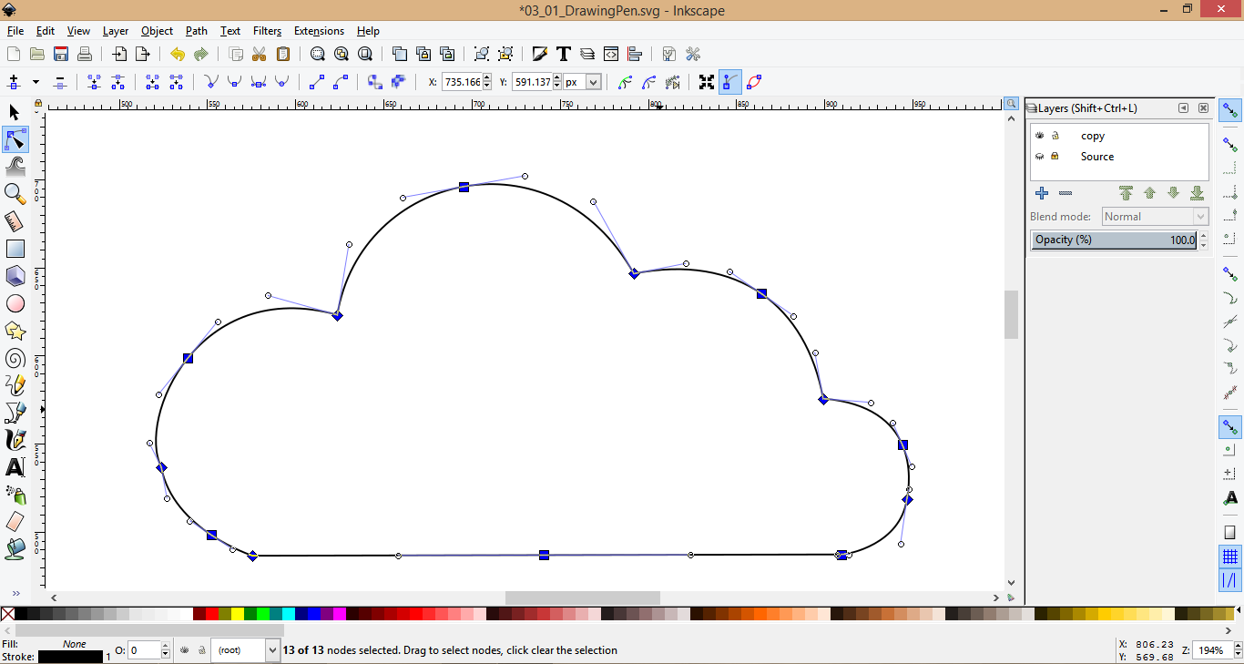
Pressing Ctrl will constrain it to horizontal or vertical. To switch between straight lines and curves, use shortcuts ‘Shift +l’ and ‘Shift + u’.
You have to pay close attention to the placement of the node. And that for generating a smooth curve in most cases the handles will be tangential to the curve and their length defines the radius of curvature. This should give you a starting reference. You can edit nodes later by pressing ‘n’.
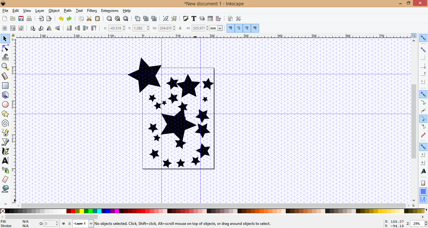
For making logos I think its better to start with a shape tool and drawing a basic shape that you can then later edit. To do this, first draw a simple shape using the shape tool.
Then select the shape and press ‘Shift +C’ this will create a path with the selected shape. Now you can edit the shape by pressing ‘n’ and edit the nodes.
![]()

SolidWorks is a Solid modeler which uses parametric feature-based approach to create models and assemblies. What that mean is that it uses parameters as contrainsts whose value determine the shape or geometry of the model. Parameters can be either numeric parameters, such as line lengths or circle diameters, or geometric parameters, such as tangent, parallel, concentric etc.
When creating a 3D model in SolidWorks. The first thing to do is to choose a template, there are 3 prebuild templates to choose from Part, Assembly, and Drawing. You can create many more. After selecting the template, now you can start creating your model. Select the dimensioning convention you want to follow from the bottom right corner of page. For most uses it would be MGS (millimeter, gram, second).
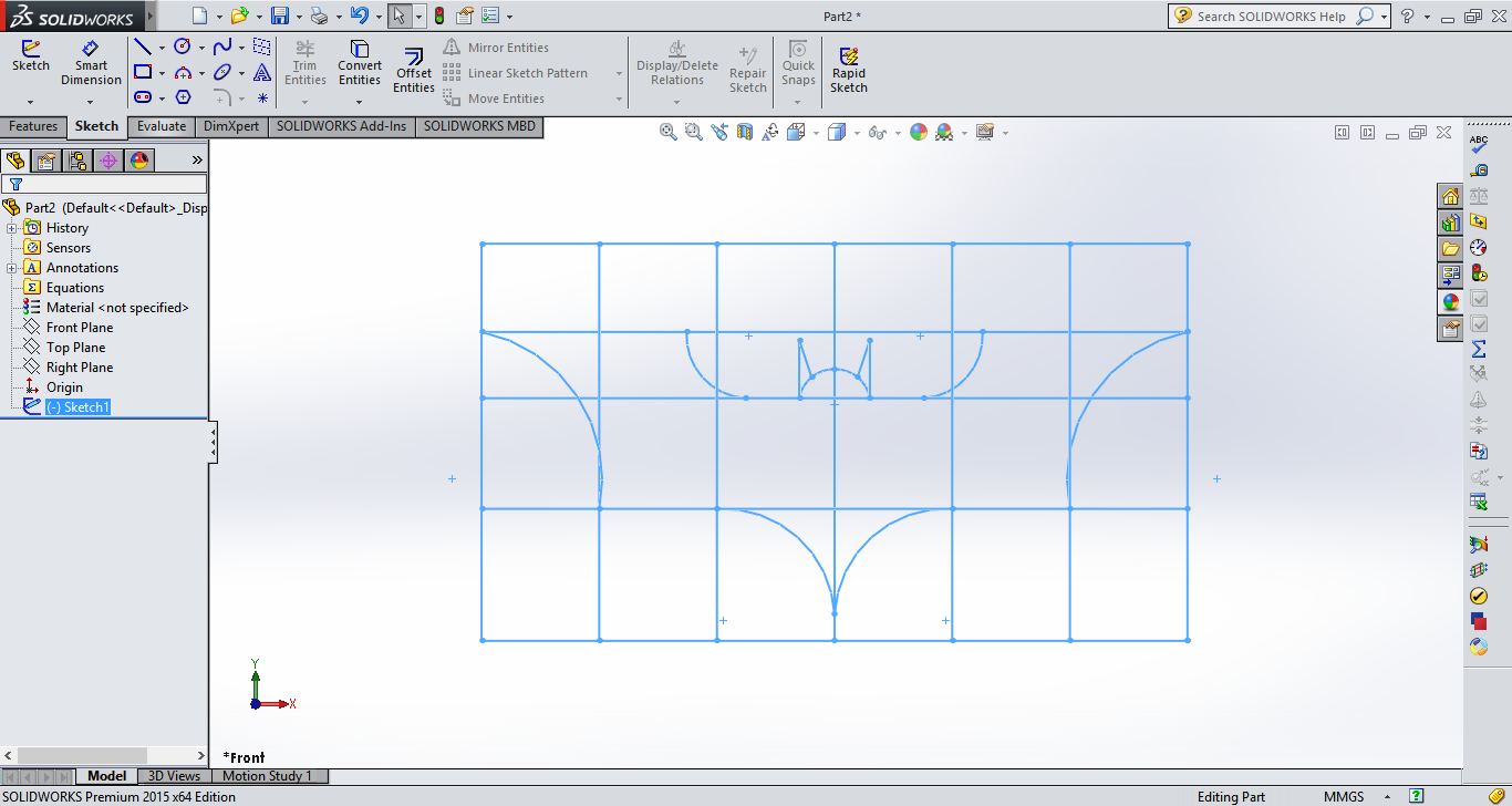
Building a model involves first creating a sketch and then extruding it into a shape with the many 3D tools. First select the sketch tool and SolidWorks will show you all the planes you can start sketching. Choose any plane by clicking on it.
Some basic sketching tools you will use are Line, Rectangle, Polygon, Circle, and Spline. The tools are intuitive, and easy to understand. In all the sketching tool, you first draw the shape then give it a dimension. You can start from the origin or any point you like. Click and drag to get your desired shape.
To give a dimension to a line or shape, select the Smart Dimensioning Tool in the top menu. Using this tool, click on the line or shape you want to give a dimension to, you can see the dimension line with a value on it. Enter a value and it will be dimensioned.
Lines are displayed in two colours in SolidWorks. Blue lines mean undefined or underdefined lines, these can be moved around and they don’t have fixed dimensions. When a line turns black, it means that it is fully defined in space. You cannot move black lines.
Once the sketch is done exit the sketch and go to feature tools. Some basic 3D tools you will use are Extrude, Extrude cut, Revolve, Revolve cut, Holes, Fillets etc.
Most 3D feature tools are driven by a sketch. These tools just add a new dimension to the sketch you have selected. The extrude tool is the most used tool in this category. Select the tool and it will show you the preview of the extruded shape. You can click and drag the arrow to change the extrude length or give an exact value.
That covers the basics of SolidWorks. I really like this tool its versatile. I plan on developing further on it in the future.

First click sketch and choose the appropriate plane, Draw the basic shape of the part, in this case a rectangle, of the appropriate dimension. Now extrude the 2D shape into the required thickness to get the 3D profile. Use the same procedure to make the top support. Now use sketch to draw the cylinder on the top plane of the support. Extrude it to the required length to get the shape. Use the fillet tool to round the edges of the model giving an appropriate radius of curvature. The hole are made by using the extrude cut tools and circles of appropriate diameter.
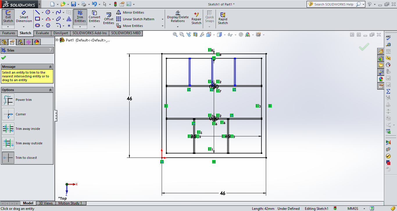
I made this when I had some free time, Its very easy to do. First use the sketch tool to draw the basic outline of the Batarang. I made some calculated guesses to arrive at my outline figure. I used the 3 point arc to draw the curves on the sides. Once your basic shape is done, use the Trim tool to cut off the lines you don’t need for the extrusions.

Use the Extrude tool to extrude the shape to 5mm thickness. Next use the Chamfer tool to finish the edges. I set the chamfer to 5mm so that it would go all the way and give a nice look.

This is a simple assembly with a Triangular base frame and Three links of different sizes. They are held together by pin joints, which allow for motion in a single plane. The parts are created with simple Sketch and Extrude method.
The assembly involves using the mate tools to constrain the different parts in 3 Dimensions, and attach them to the base.
For motion simulation, go to the bottom menu to select the motion study tab. There is a menu for adding an Electric Motor to the links. Click the menu and set the RPM and direction of rotation. When you click the play button you can see the links move. Similarly I added the Electric Motor to the rest of the links. You can export the study as an .avi file.
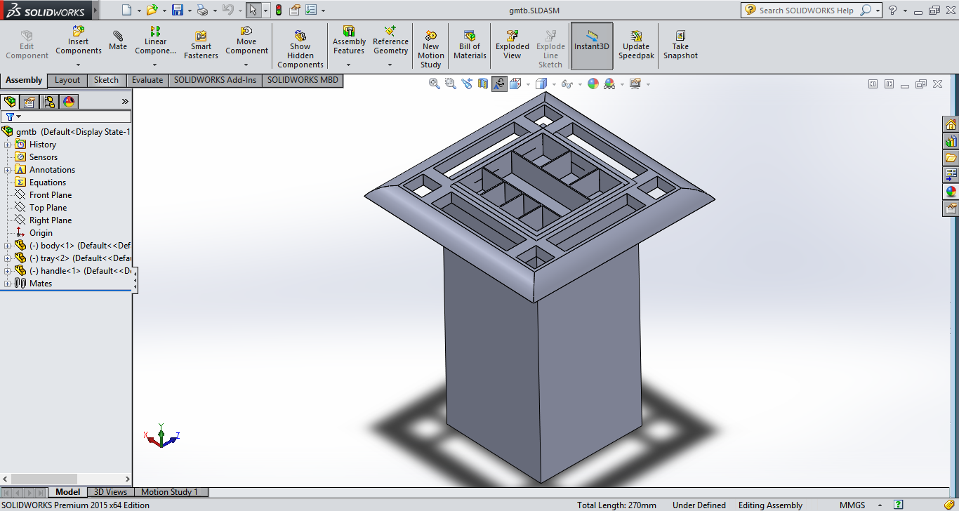
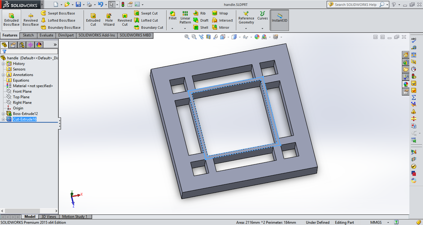
I’m planning to make a Guided Mobile Robot Toolbox. Hence the design I intent to use is a simple box shape with a handle for moving the robot manually, and motorized wheel at the bottom for anonymous navigation of the tool box.

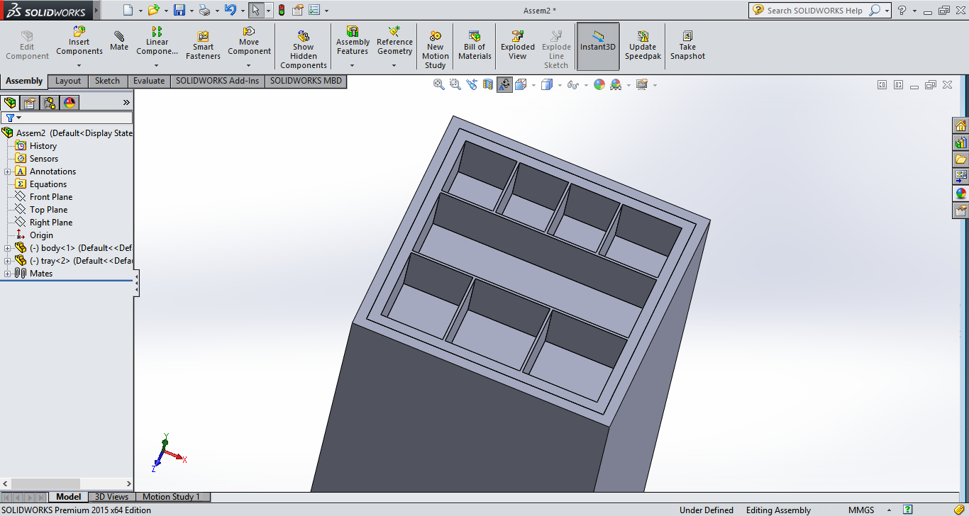
I’ve designed the top tray to be divided into smaller spaces so that the tools on top of the tool box will be organized and easy to find.

Geared wheels driven by DC motors will be mounted on the bottom which will provide mobility to the robot and ultrasonic sensors will be used to detect the presence of the user.
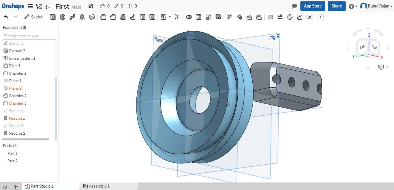
Onshape is a professional Computer Aided Design Software delivered over the Internet via a Software as a service (Saas) model. User interact with the CAD system using their browsers. It is the first CAD system designed to operate entirely in the cloud. It is free to use but you can save your documents as public only. For private documents paid memberships are necessary.
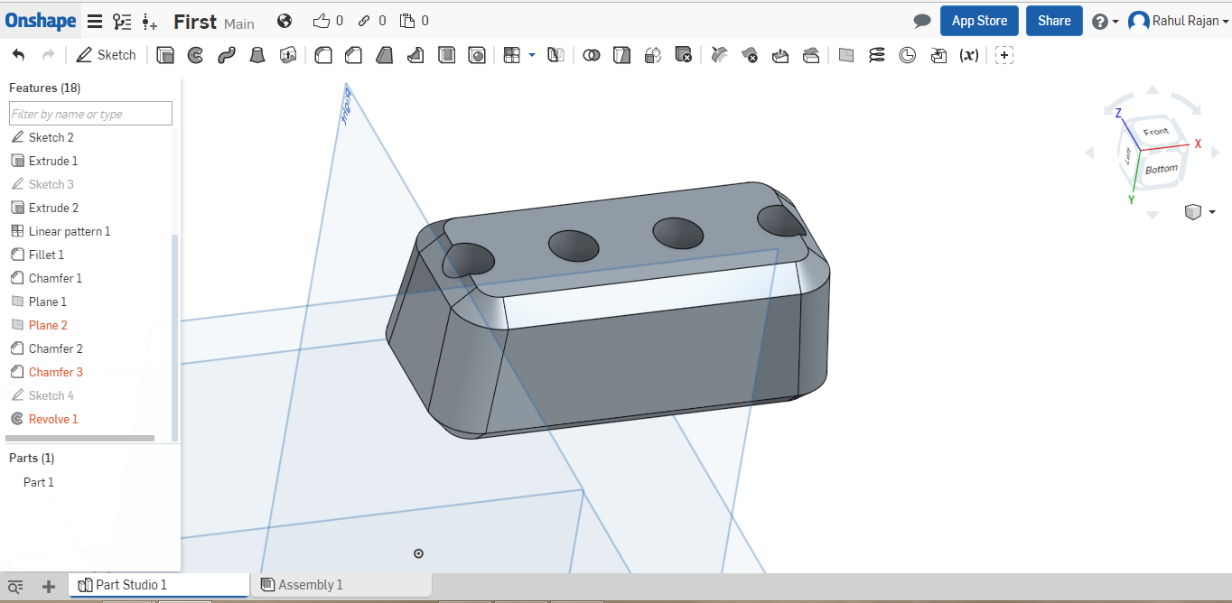
Onshape and SolidWorks both have the same tools, The only difference being the layout of the placement of the tools, being familiar with SolidWorks will help a great deal in using this software. I tried out some basic 3D modeling and found it very easy to use. Even though it is browser based, It does require quite a bit of precessing power.
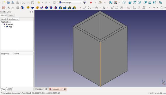
I installed FreeCAD on my system using the terminal by typing sudo apt-get
install freecad It was available in the repository. I tried to follow some
tutorials to learn the fundamentals to create a basic shape. Having used
Solidworks before I found it a bit harder to do routine tasks like
extruding and giving dimensions. It takes time to find out where the tool
you want to use are, but I guess it is because of my lack of familiarity with
the software.
Creating basic 3D models follows the same procedure as SolidWorks. You first create a Sketch, by going on to the sketch tool and selecting a plane, and then add dimensions and constraints to it, to create a fully defined sketch. Once sketching is done use pad tool to extrude it to a suitable dimension.
Since it is free, its a good alternative to Solidworks. The logic behind them is the same and for basic part design, I think this will suffice.

Tinkercad is a free online platform built by Autodesk. I really liked this software for its usability. It's quick and the tools are very intuitive. Its designed to be a simple CAD tool for creating basic shapes, geared towards 3D printing.
All parts are drag and drop. If you need to create a solid shape just choose from the menu on the right, drag and drop it into place on the plane. When you click on a part it will show you all the dimensions and arrows for moving and transforming the object. For changing the dimension, just click and drag the shape using any of the arrows in the direction you want to transform. Alternatively, you can even input a custom dimension.
I created a lego brick by using a Rectangle as the base shape and adding 4 cylinders in the op as teeth and four on the bottom as holes.
I find this tool very easy to use, but the features are pretty basic. This works wonderfully when you want to quickly 3D print a basic part for your product, for which you won’t need a full on CAD program.
When I tried to install a software called 'Phatch' for reducing the size of the images. I met with this error, I search online and found that it is because that software requires some other packages to be pre installed on the system.
To fix this try and install the software through the terminal using sudo apt-get package name
Then when it shows the error, type sudo apt-get install -f To install the unmet dependencies.
rahulsrajan.com
rahulsrajan01@gmail.com
Trivandrum, Kerala ,
India.

Technopark, Kerala, India

