The main purpose of using an IC for building our electronics is because we can control a wide range of output devices with it. This week I will be designing and building my own stepper driver. In almost all CNC machine we use stepper motors to control the different axes. But stepper motors are a lot harder to drive than regular DC motors. I wanted to make the driver because I want to build a CNC machine in the future.

A stepper motor is a brushless DC electric motor that divides a full rotation into a number of equal steps. The motor's position can then be commanded to move and hold at one of these steps without any feedback sensor.
They have multiple coils that are organized in groups called "phases". By energizing each phase in sequence, the motor will rotate, one step at a time.
You cannot drive a stepper motor like a DC motor by just connecting the Supply and Ground. A stepper usually has two sets of windings. If you give power to one set of winding the stepper will be locked in that position. It will resist the motion till a torque greater than the Holding torque of the motor is reached. In order to drive the motor you have to energize the windings in a particular sequence. The sequence is depended on the type of windings you have.
An unipolar stepper motor has one winding with center tap per phase. Each section of windings is switched on for each direction of magnetic field. Since in this arrangement a magnetic pole can be reversed without switching the direction of current, the commutation circuit can be made very simple (a single transistor) for each winding. For a given phase, the center tap of each winding is made common: giving three leads per phase and six leads for a typical two phase motor. Often, these two phase commons are internally joined, so the motor has only five leads.

Bipolar motors have a single winding per phase. The current in a winding needs to be reversed in order to reverse a magnetic pole, so the driving circuit must be more complicated, typically with an H-bridge arrangement. There are two leads per phase, none are common.
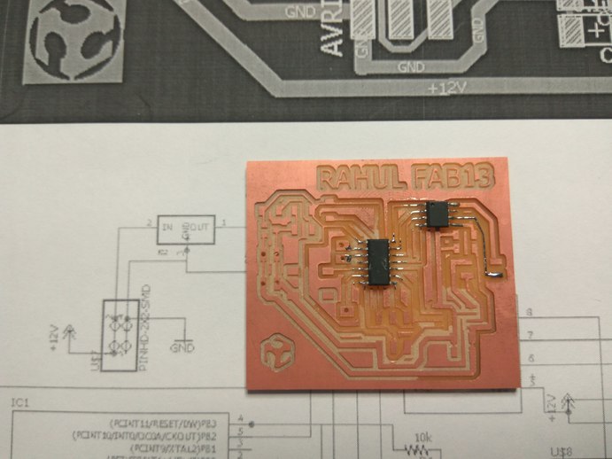
I'm going to make a stepper driver for a Bipolar stepper motor. I'm designing a board inspired form Neil's hello stepper board. The board will have an Attiny44 as the controller and use two half H-bridges to drive the stepper. There are a still some pins left on the attiny, hence I've added an extra button to PB2 to work as an interrupt switch and an LED to indicate Power.
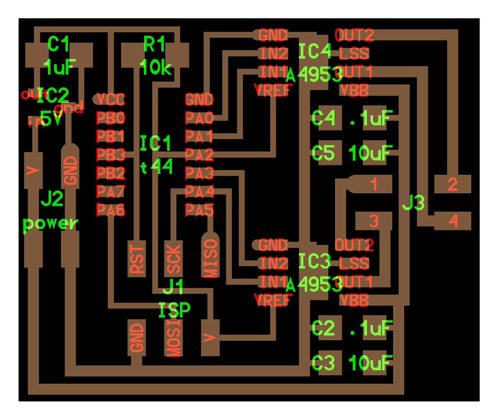
My first step is to understand Neil's board and why all the components are placed where there are. The Attiny is used to control the board, it can be programmed to run the stepper. There are two voltage requirements for this board. One is 5V VCC to the micro controller, and the other is the 12V supply to the motor. We use an H bridge to connect the micro controller to the Stepper.
The H-bridge in this circuit is used as a fast acting switch. The H-bridge consist of two Mosfets one of P type and other of N type. When we give an input to one of its Input pins, It connects the High current circuit to the motor. In this way we can control a high current motor with a Micro controller.

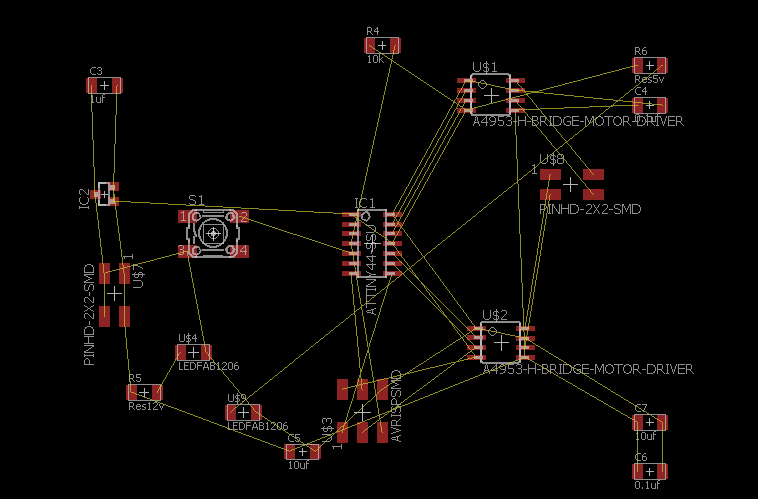
I used EAGLE to draw the schematic after understanding all the connections. The switch was added to PB2 as an interrupt and LED is connected across VCC and GND to show power to the circuit. I add LEDs to the circuit so that It becomes easier to debug any problems. Sometimes the connection between FAB ISP and board is not perfect. It helps a lot having an LED on the board. Plus it looks cool.
Routing this board is a lot harder than I thought. I have explained detailed steps about routing on my Electronics Design week, those are the same steps I used to route my board. The problem is that the smallest bit we have is a 16 mil bit. This is wide in terms of PCBs, hence we can't really cut two traces inside the space occupied by an Attiny or 2x2 headers. This means routing become a much harder task.

There was also another thing we have to worry about. The steppers are connected to a High current circuit. This means it needs thicker traces to withstand the current. I used an online calculator to find the thickness of traces necessary. I rounded the figure to a thickness of 40mil. This poses extra challenges in routing as thicker traces occupy more space.
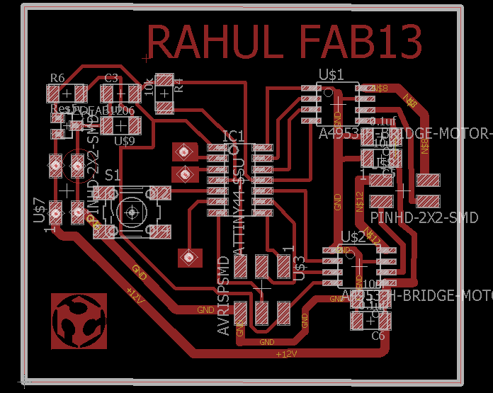
It took me some time but, finally I finished routing the board. I've added some text and fablab logo. The logo I imported as a bit map. You need to run a script to add bitmaps, I've explained how to do that in my electronics design week.
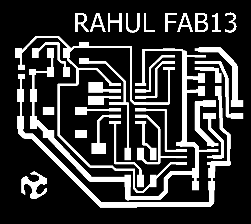
The final traces, you can see some connections going to the stepper are smaller than others. I reduced the size so that I could route them. I won't over load the motors, and I'm hoping the connections will be enough.
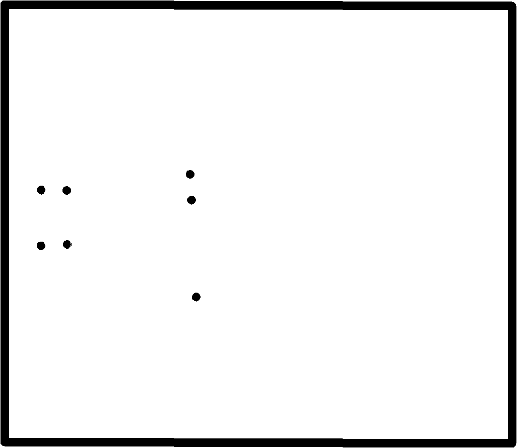
I've added drill holes to the cut out as I've draw out the unused pins on the Attiny and want to connect headers to them. I've done this previously by just giving pads, but it did not work properly, The traces peeled off. hence I'm going to drill them on the board to fix them properly.
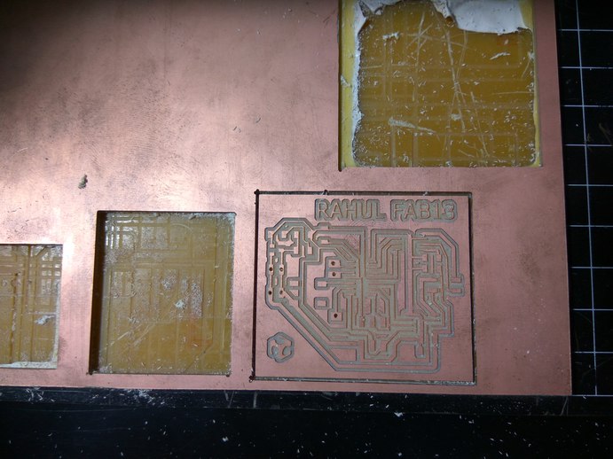
The board was milled using Modella MDX 20 The traces are cut out using a 16mil bit and the cut out was milled using a 32mil bit. The 16mil bits are very fragile, we have broken a few. Always take care when loading and unloading the bit. make sure the bit is properly tightened on both sides of the chuck. I have explained the procedure for milling using the Modella on my Electronics Design week.
Soldering the board was straigh forward, make sure the pins are aligned and oriented properly. Since I've made a couple of board before I'm getting used to soldering small components. The trick in soldering an IC to board is to first put a dab of solder on one of the pads. Then align the IC properly using the tweezers, making sure that all the pins are lined up with the pads. Now heat the pad so that the solder melts and bonds the pins. Now go ahead and join all the rest of the pins, and come back and solder this pad properly.
The point of the first one is to hold the IC in place while you connect the rest of the pins.
I've covered one of the traces with a layer of solder. The reason is that When the connection was milled out the trace came out smaller than I had anticipated. I played with the clearance a bit when designing my board. Hence I hooped that a layer of solder would give the material some thickness to withstand the high current that will pass thorough it. In the end it did held up nicely.
I faced a lot of problems in this phase. I'll state them in the order which they occurred.
The first one was that I've attached a 5V 100ma Voltage regulator to my board so that I can power both the stepper and the Attiny with the same supply. This is the same component which Neil used on his board.
The probelm I was facing was that the regulator was getting really hot when I connect my board to my laptop using my programmer. I double checked all the connections to make sure that there was no short in the circuit. Then I checked the component to see if it was faulty. I tested it using a variable voltage source and found that even when I apply 12V DC to the input the output still remains at 4.9 to 5V.
I then triple checked the connections and went back and referred my schematic to see if I had given a wrong connection anywhere. It checks out all the connections seem to be good. The component overheats only when I connect to my laptop. Then I tried powering the board by giving supply to the ISP header on my board where the serial cable connects. After giving 5V to the VCC and GND on the ISP header The board powered on and the regulator was fine.
For some mysterirous reason the regular gets hot only when the rest of the MISO, MOSI pins of the header are connected. One thing I realize might be the problem is that the laptop is sending more current than necessary in the reverse direction and that might be the reason for it getting hot suddenly. Left with no other option, I decided to remove the voltage regulator. Now I will have to power my board and my motor separately.
The second problem that I faced was that Neil's hello stepper code was not working. After flashing the board with my programmer and connecting it to the stepper motor, I powered on the board and the motor to find that the motor is going back and forth at high speed, its like its vibrating.
My pinouts are almost the same as Neil's So I did not understand what was going wrong, was it my connections or something wrong with the way I connected the motor.
I'm using a bipolar motor which has 4 wires. Red,blue,black,green. After searching for the motor in fab inventory I goggled online to find its datasheet. I searched for the part number and only one site showed up. I read the datasheet provided on the site. It showed that the pins go from one to four in the order, Red,Red,blue,black,green. I connected the stepper to the board, using jumper cables in the same order. Flashed Neil's code and powered it up. The board kept vibrating in place.
After checking the connections one more time. I wanted to see what kind of output I'm getting. It's time to roll out the big guns. Enter the Digital Oscilloscope.
The oscilloscope is device used to visualize the output waveforms generated form the circuit. It has two leads, one ground and another lead you touch on the pins you want to see the output.

I spend a lot of time testing all the outputs form the various connections. The connections seem to be good, I was able get outputs from all the pins. There was 5V output from the Attiny and 12V output from both the H-bridges.
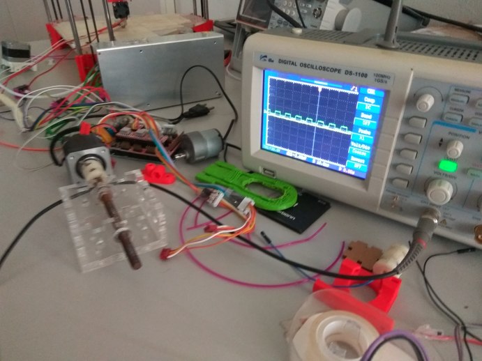
The next thing I checked was to see what kind of output I'm getting from my H bridges. After testing all the connections, I found that two pins have a square wave output and are always High and the other two pins are always low. So the program is working, Its sending PWM waves as output from the H bridge, So the next thing on my mind was figuring out if there was anything wrong with the program.
With a lot of help from my instructors, I sat down and read through Neils Code and understood what all the functions did. This was very hard. Neil's code is not easily understood by ordinary people like me. In time we understood how he used functions to segment the code and then only I understood the beauty of it. The code is written in a way such that parts of it can be separately reused, hence all the functions.

After spending hours on reading about the logic to drive stepper motors, I began to write my code for a simple clockwise motion of the stepper one step at a time. I understood that in order to move the stepper one has to charge the coils in a sequence such that the poles are always jumping from one winding to the next.

I was referring to this datasheet to find out the pin outs of my stepper motor. From the data sheet I could get the sequence for the wires and the order in which I need to charge them to make the stepper move. I noticed from the datasheet that the black and green wires were denoted as A and A-. Neil denoted them as A1 and A2. ONe thing that was peculiar was that Neils A1 and A2 does and The A,A- of my datasheet do not match. They are different wires and connected to different pins. I don't know why this is, I may be looking at the wrong datasheet, but this was the one I found when I searched the part number from the Fab inventory.
Working with this in mind I edited Neil's code to correspond to the pins on my motor and flashed that code to the chip and connected my board to the supply. Still the same thing happened and the motor kept vibrating. Now I was really confused. The connections were good the code is working but the stepper is not doing what it is supposed to.
I disconnected thee stepper from the board and tried all possible ways to connect it, I mixed up the order each time and powered the board to see what will happen. In many attempts the motor did not move at all, but I got lucky. In my last attempt when I connected the stepper in a new order the motor started moving. I was both relieved and confused. Maybe I had messed some connections while designing my board. Maybe I was using a different motor, or quite possibly I was looking at the wrong datasheet.
After hours of testing it finally came down to a mixup of connection going into the stepper motor.
My confusion has not fully left me, In the original datasheet the Pin numberings of stepper motor from 1 to 4 are Red,Blue,Black,Green respectively. But in my board the stepper worked when I connected them in the order Green, Red, Black, Blue. This might be because I made a mistake somewhere that I do not yet realize, but for now this seems to be the connection that works.
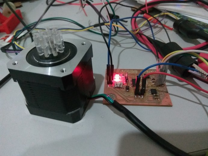
After changing Neil's code to correspond to the pin outs of my board, I flashed the program and connected the supply. Finally The motor started turning. This was a welcome relief after more than two days of debugging.
I also noticed that sometimes the stepper would only move when there is some load attached to it. I understand this is a common problem, hence when I attached a new stepper from a previous project which had a lead screw and carriage attached the stepper worked flawlessly.
After studying Neils hello stepper code, I wrote a code to run my stepper in a clockwise direction one step at a time. I went through Neils function on turning the stepper in clockwise direction and applied the same logic here. The code is designed to charge the coils in a specific sequence so that the rotor would rotate withe the rotating magnetic field.
#include<avr/io.h>
#include<util/delay.h>

main()
{
  DDRA = 0b00011011;

  CLKPR = (1 << CLKPCE);
  CLKPR = (0 << CLKPS3) | (0 << CLKPS2) | (0 << CLKPS1) | (0 << CLKPS0);

  while (1)
  {
    PORTA = 0b11110110; //    PA1, PA4
    _delay_ms(100);
    PORTA = 0b11110101; //    PA0, PA4
    _delay_ms(100);
    PORTA = 0b11101101; //    PA0, PA3
    _delay_ms(100);
    PORTA = 0b11100111; //    PA0, PA1
    _delay_ms(100);

  }

}
Overall this week was a challenging and fun week, I learned a lot about stepper motors and how they work. I still have a long way to go but, I plan on using what I have learned when I make my CNC machine.
rahulsrajan.com
rahulsrajan01@gmail.com
Trivandrum, Kerala ,
India.

Technopark, Kerala, India

