Week 13
Input Devices
Objectives
Learning Outcomes
Have I ...
Documentation
This assignment I am going to do two input devices, one is temperature sensor and magnetic sensor. The last in order to advance my final project, because, when a magnet touch the juggling club it changes of color. So, I need to test voltage that sensor return. I am going to design a magnetic sensor board, just with sensor and capacitor because it going to work with Jhonduino so I need the out voltage.
Sensor boards
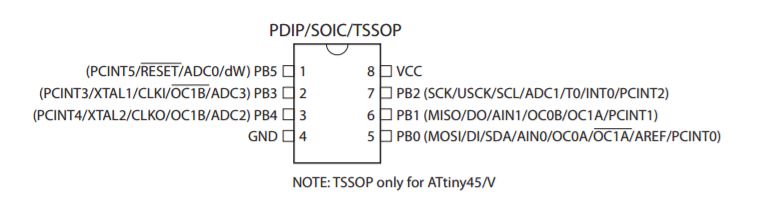
Temperature and magnetic boards use Attiny 45 (temperature and magnetic). For that reason, I cheked its data sheet to understand how it works, operations and connections.
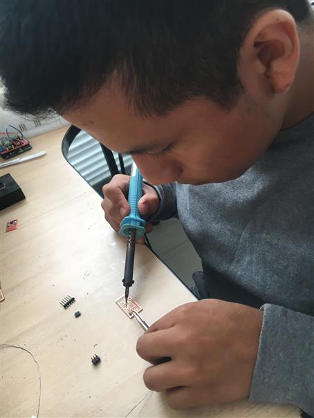
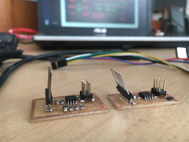
After milling both boards, let to weld electronics components like previous ones. Finally, boards are ready to be programmed.
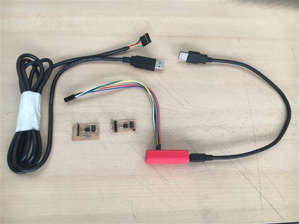
Ready to programm, take at hand FTDI cable and fabISP.
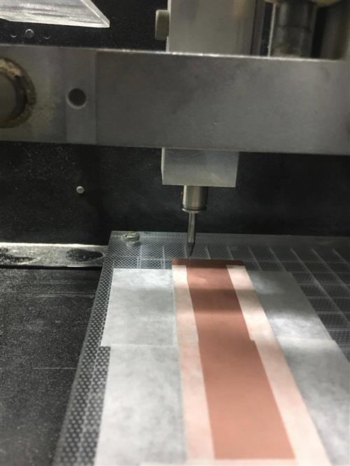
How to mill a board?
I design a magnetic board for my final project. So I am going to explain step by step how I did.
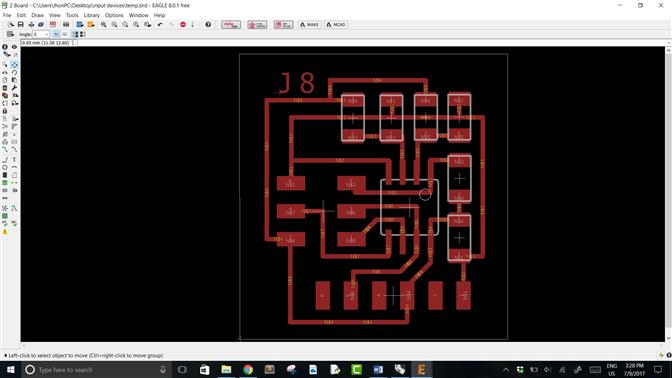
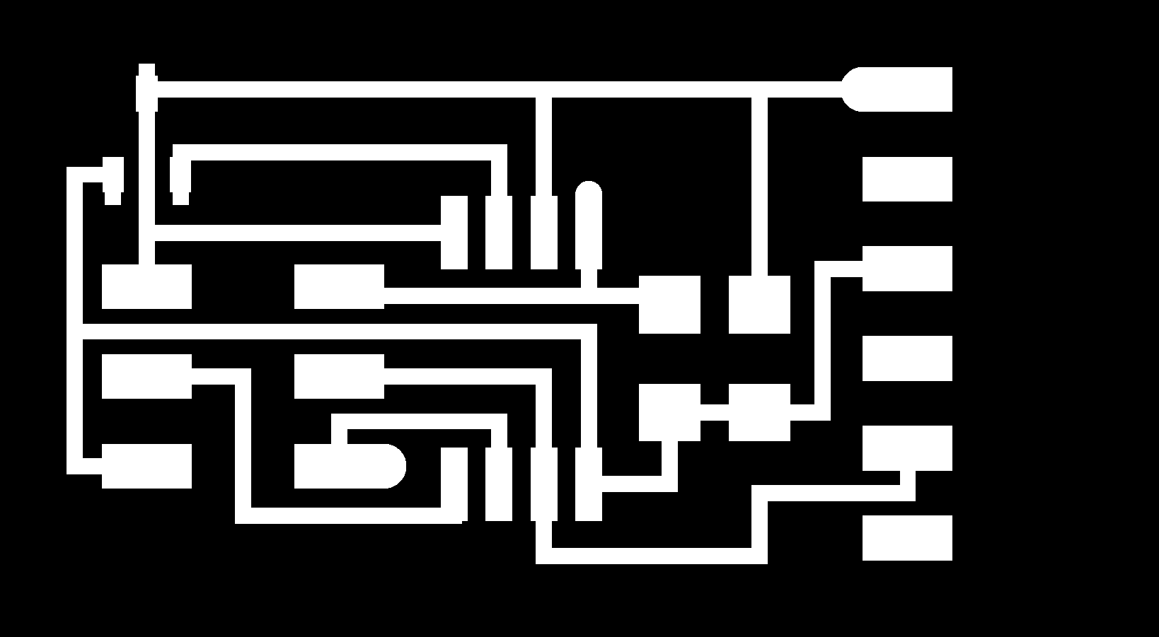
1. Using eagle I design my schematic and board. I check magnetic sensor datasheet.

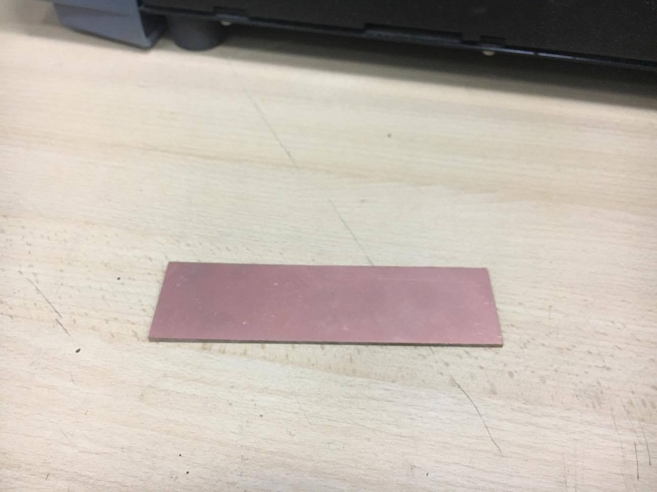
2. Files are at bottom. 3. Choose a new piece of board. I chose a piece from a previous job.
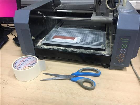
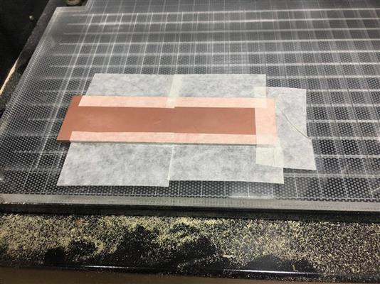
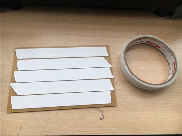
4. Using maskint tape.
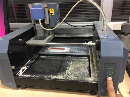
5.Once the board is placed, press VIEW bottom.
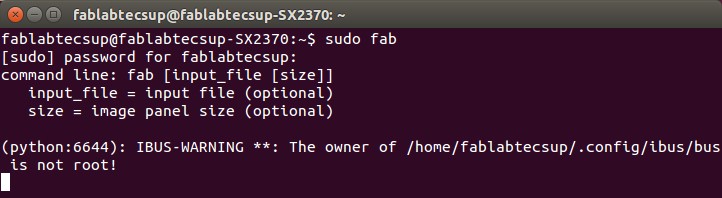
6.Open Ubuntu terminal and write "sudo bash", press Enter.
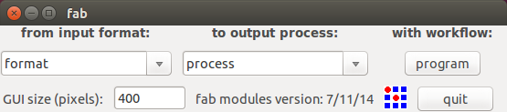
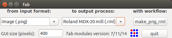
7.There will appear a window, let to set "image(.png)","Roland MDX-20 mill(.rml)" and click on "make_png_rml".
8.There will appear a new window, let to set "mill traces (1/64)" at top, click on "load.png" to load a image. At the middle, value of "4" for "offsets (-1 to fill)" [4 or other number means quantify of rough pass]. A value "0.1" for "error (pixels)" to get a better finish. The rest do not touch.
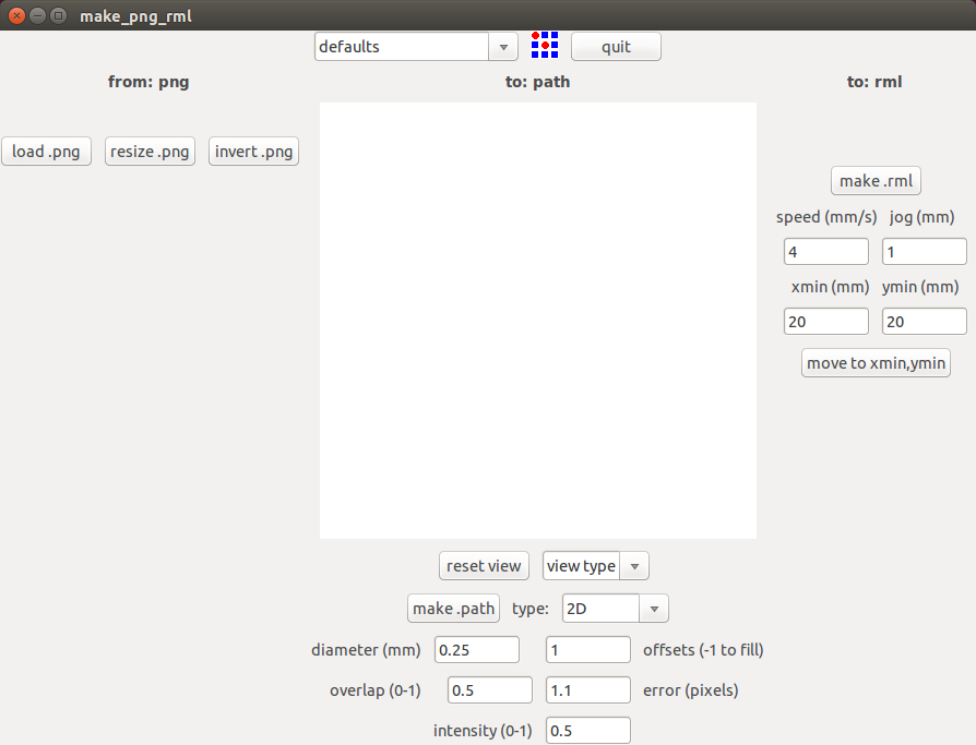
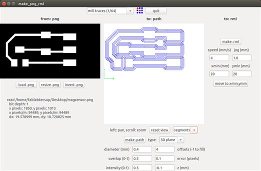
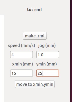
9.On your right, let to set milling tool position. Test 20mm on Xmin and 20mm on Ymin.
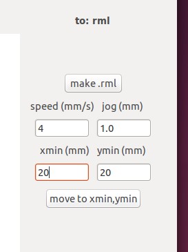
Now, calculate how much is missing for each axis and enter. And to set Z axis, have to use UP and DOWN buttons. USE SLOWLY BECAUSE COULD CRASH MILLING TOOL!
10.Once position was setting. Click on "make.rml". It is HIGHLY RECOMMENDED choose a "2" value for "speed(mm/s)" . Thus the milling tool has a longer period of life.
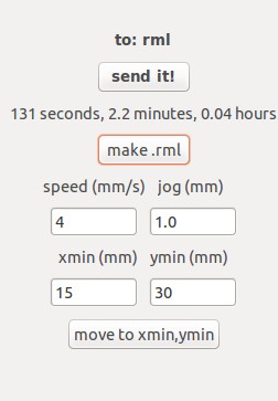
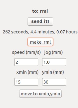
11.Click on "send it!"
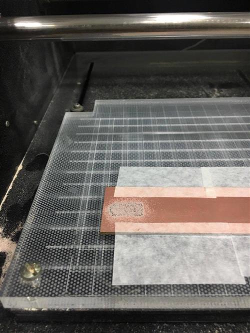
12. When, modela finish, could use a toothbrush to clean the chip.
Temperature sensor
Let to programm this board. You need to download make file, .c file and .py file.
Now, open terminal, enter to file where those were downloaded.
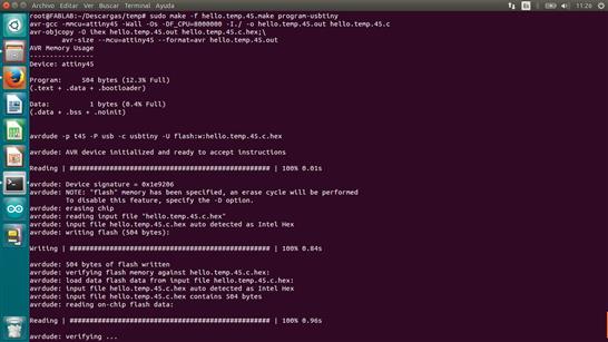
sudo make -f hello.temp.45.make program-usbtiny
avrdude -p t45 -c usbtiny -U flash:w:hello.temp.45.c.hex
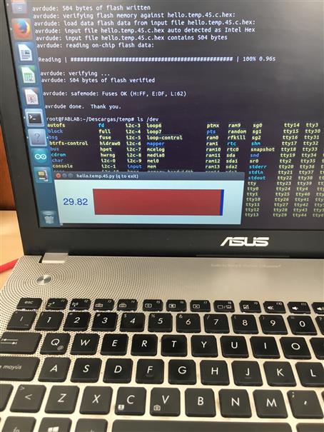
Now, to interact with sensor let to open .py file. Open terminal and write line code below.
python hello.light.45.py /dev/ttyUSB1
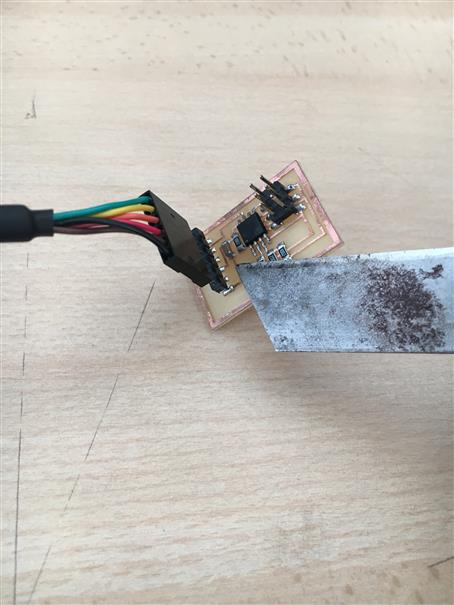
I warmed the tip pf cutter for a few seconds and touch temperature sensor. It is working!!
Making my own Temperature sensor board
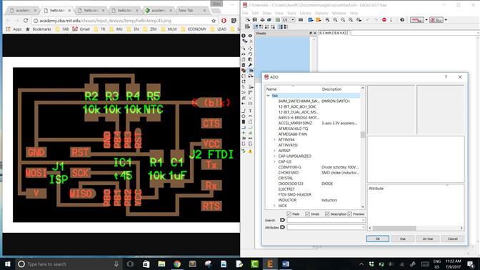
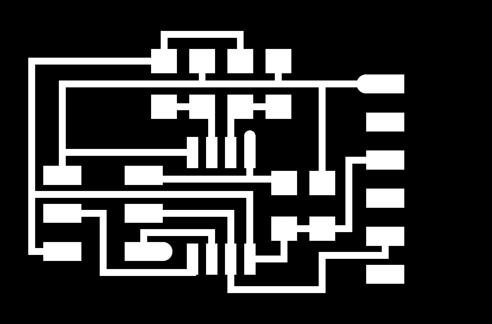
I redesign Neil's temperature sensor board. As always in all my electronic designs I add my style that is to make it as compact as possible to reduce its size. I did reverse engineering to obtain schematic. I opened Neil's board in one window and Eagle. Using "Add" tool components were added. One tip is to place the components in a way that when making the connections does not have many crosses.
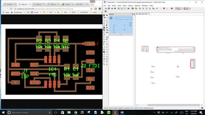
Once components were placed. Let to do connections using "Net" tool. Another tip, made a "Junction" in cross conections to ensure they are linked.
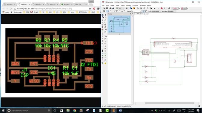
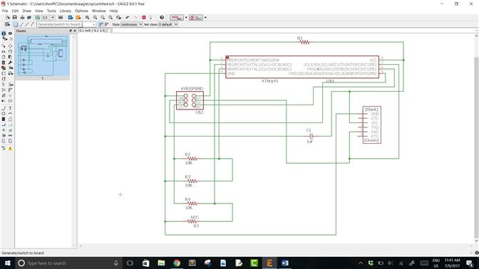
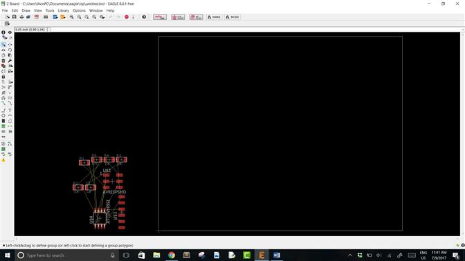
Now, click on "Generate/switch to board" (on top). There will apear a new window which contains our components united by yellow lines. Using "Move" tool let's to move components inside the white line, which delimits the work area and the size of our board.
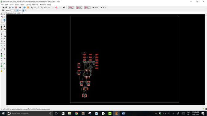
When electronic components were placed. Using "Route" tool let to do paths. Whole components and paths have to be inside white line. Use the "Move" tool to adjust the white line to the card size.
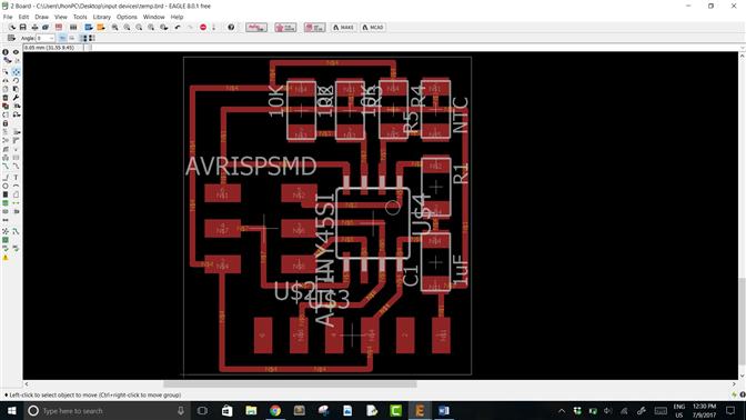
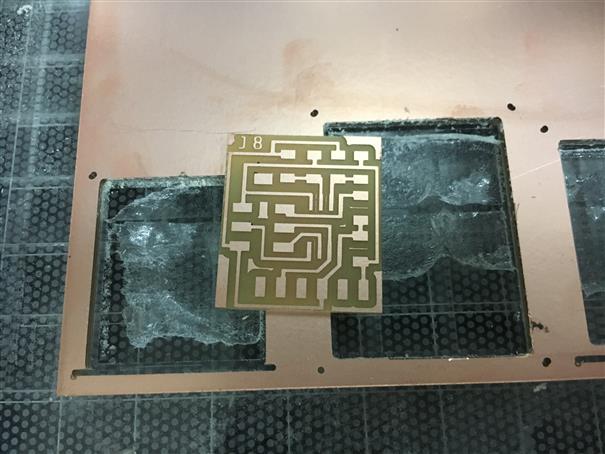
Once my card were finished I add "J8", "J" by my name (Jhon) and 8 a special number (8-may my father died). To export .png file. Click on "File / Export / Image", choose the folder where it will be saved, click on "Monochrome", "2400" dpi, area "Full" and click on "OK".
LET'S TO MAKE OUR BOARD!!
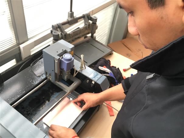
Choose a copper PC board and apply stick tape double contact.
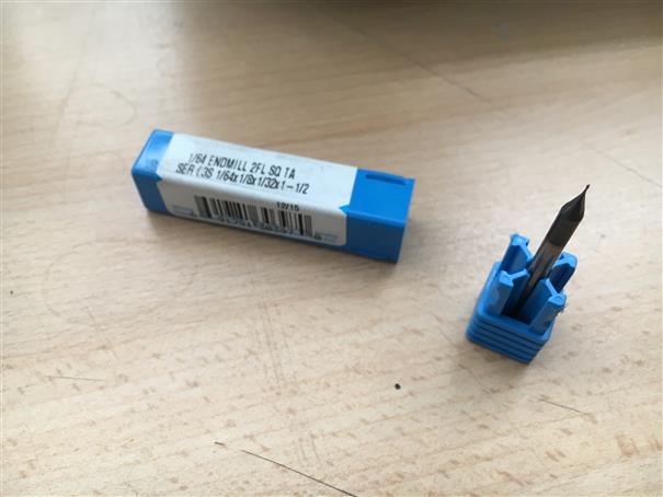
Look for a 1/64" milling tool. Using a allen wrench change it. For this, one hand is under the milling tool and the other hand misaligns the prisoner, in this way milling tool that comes out does not fall, preventing it from being hurt. Change for 1/64" in the same way as you removed the milling tool.
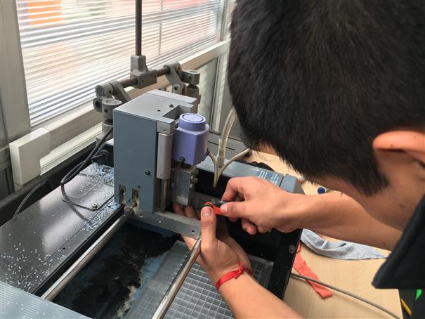
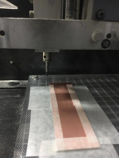
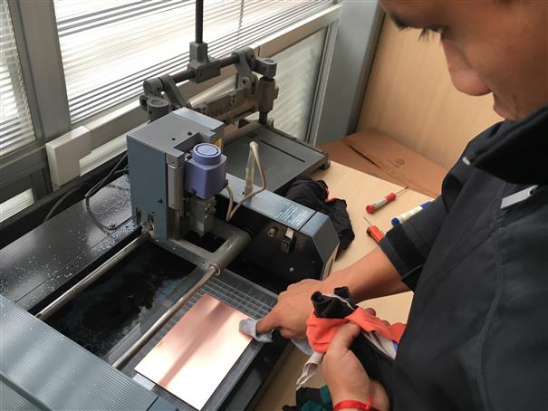
Now, place copper PC board on Modela base. Using a cloth press for a better glue.
Using Fab modules send traces .png using 1/64" milling tool, check parameters on top side of this assignment.
Change 1/64" by 1/32" milling tool to cut our board using outline .png file.
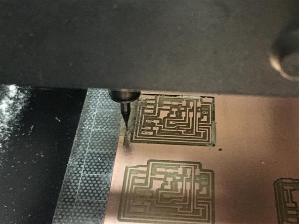
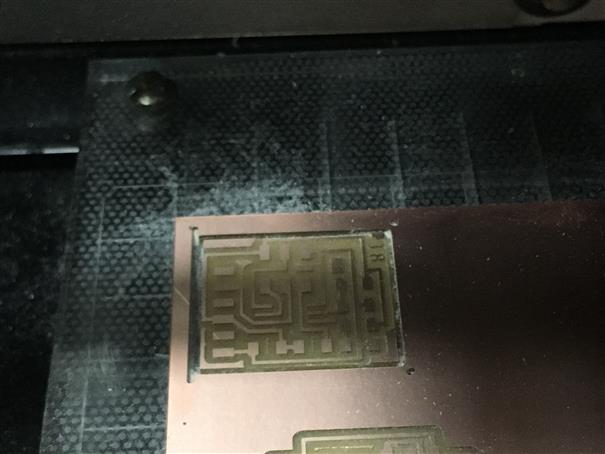
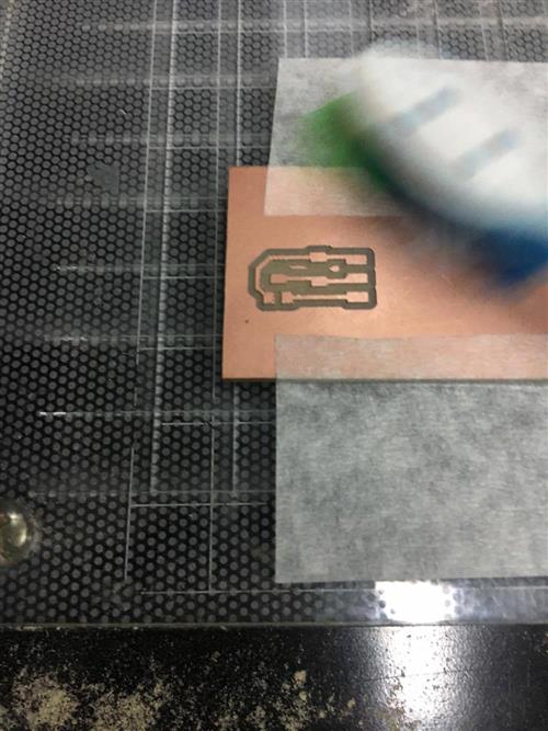
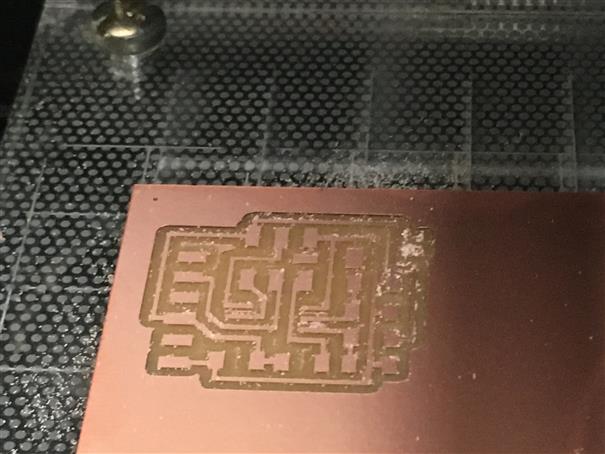
Milling of temperature sensor board, done. In this way we can use all copper PC board possible.
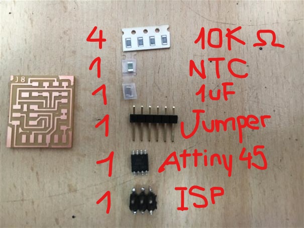
Look for electronic components.
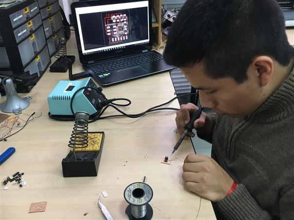
Weld the components. Always carefully!
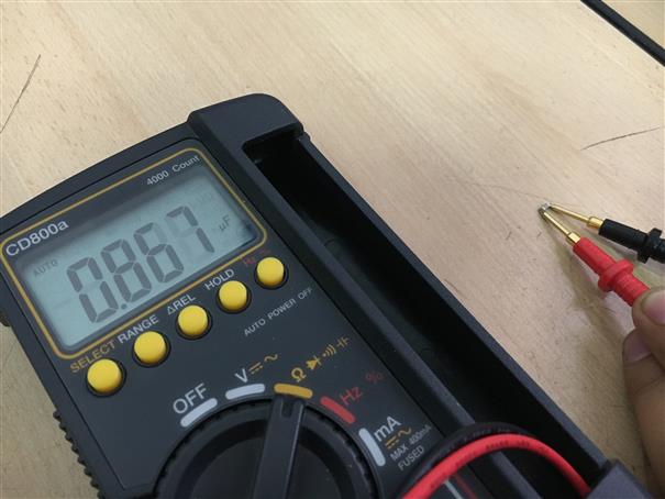
I had confusion with the capacitors because they looks similar. A good help is to use a multimeter to measure the capacitance of the capacitor and be sure to use the correct one.
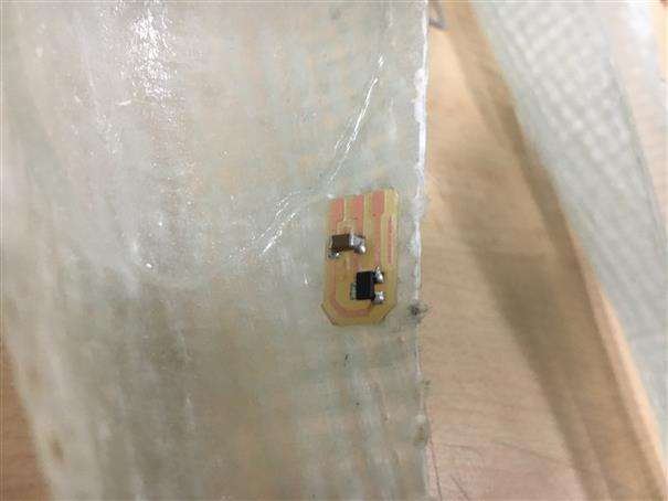
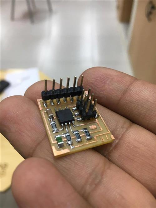
Finally, work done!
Magnetic sensor
Let to programm this board. You need to download make file, .c file and .py file.
Now, open terminal, enter to file where those were downloaded.
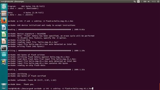
sudo make -f hello.mag.45.make program-usbtiny
avrdude -p t45 -c usbtiny -U flash:w:hello.mag.45.c.hex
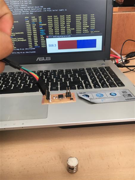
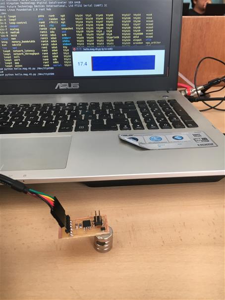
Now, to interact with sensor let to open .py file. Open terminal and write line code below.
python hello.mag.45.py /dev/ttyUSB1